Magtek MICRSAFE Technical Reference Manual
Hide thumbs
Also See for MICRSAFE:
- Quick installation manual (2 pages) ,
- Quick installation quide (2 pages) ,
- Technical reference manual (83 pages)
Table of Contents

Related Manuals for Magtek MICRSAFE


Summary of Contents for Magtek MICRSAFE
- Page 1 MICRSAFE TECHNICAL REFERENCE MANUAL Manual Part Number: 99875466-3 OCTOBER 2010 REGISTERED TO ISO 9001:2008 1710 Apollo Court Seal Beach, CA 90740 Phone: (562) 546-6400 FAX: (562) 546-6301 Technical Support: (651) 415-6800 www.magtek.com...
- Page 2 Information in this document is subject to change without notice. No part of this document may be reproduced or transmitted in any form or by any means, electronic or mechanical, for any purpose, without the express written permission of MagTek, Inc. MagTek is a registered trademark of MagTek, Inc.
- Page 3 This warranty shall be provided only for a period of one year from the date of the shipment of the product from MagTek (the “Warranty Period”). This warranty shall apply only to the “Buyer” (the original purchaser, unless that entity resells the product as authorized by MagTek, in which event this warranty shall apply only to the first repurchaser).
- Page 4 FCC WARNING STATEMENT This equipment has been tested and was found to comply with the limits for a Class B digital device pursuant to Part 15 of FCC Rules. These limits are designed to provide reasonable protection against harmful interference when the equipment is operated in a residential environment.
-
Page 5: Table Of Contents
Contents SECTION 1. OVERVIEW ..........................1 FEATURES ............................... 2 ACCESSORIES ............................2 SOFTWARE DRIVERS REQUIRED ......................2 REFERENCE DOCUMENTS ........................3 SPECIFICATIONS............................. 3 SECTION 2. INSTALLATION........................5 REQUIREMENTS............................5 PROCEDURE ............................5 USB DRIVER INSTALLATION (WINDOWS) .................... 6 SECTION 3. OPERATION ........................... 7 CHECK READING PROCEDURE...................... - Page 6 APPENDIX C. TROUBLESHOOTING GUIDE ................... 53 REQUIREMENTS............................ 53 SET-UP ..............................53 CHECK LED ..........................53 CHECK THE POWER TO THE MICRSAFE ................54 READ A CHECK ......................... 54 DID PC RECEIVE DATA? ......................54 ANALYZE DATA ......................... 54 VERIFY PARAMETERS ......................55 READ ERROR..........................
- Page 7 FIGURES and TABLES Figure 1-1. MICRSafe with 3-Track MSR ....................viii Table 1-1. Specifications ..........................3 Figure 3-1. Check Orientation ........................7 Table 3-1. LED indicators ..........................8 Table 4-2. SWB Command......................... 11 Table 4-3. Control Characters ........................12 Table 4-4. Error and Status Codes ......................13 Table 4-5.
-
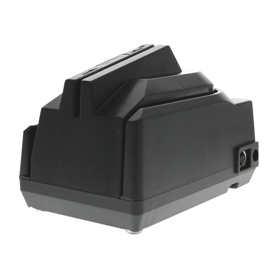
Page 8: Figure 1-1. Micrsafe With 3-Track Msr
Figure 1-1. MICRSafe with 3-Track MSR viii... -
Page 9: Section 1. Overview
Host device. The Host device then uses a specific authorization or verification process to validate a business transaction. The use of the MICRSafe improves accuracy and speed because there is no manual data entry; therefore there are no keying errors or unwanted delays. -
Page 10: Features
MICRSafe device(s) to use a VCOM port. In that case, you would need to download the VCOM driver from the MagTek website. This driver allows a USB device such as the MICRSafe to appear as an additional COM port available to the PC, enabling application software to access the USB device as if it were connected via a standard COM (RS-232) port. -
Page 11: Reference Documents
Corporation, Intel Corporation, Microsoft Corporation, NEC Corporation USB Implementers Forum, Inc., www.usb.org ANS X9.24-2004 Retail Financial Services Symmetric Key Management Part 1: Using Symmetric Techniques SPECIFICATIONS Table 1-1 lists the specifications for the MICRSafe device: Table 1-1. Specifications OPERATING Reference Standards ISO/CDL/AAMVA... - Page 12 MICRSafe with 3-Track MSR...
-
Page 13: Section 2. Installation
5. The first time the Reader is connected to the PC, Windows will need to install the USB driver. See the instructions below. 6. The LED indicator on the MICRSafe should turn on to a steady green. The LED indicator is located to the left of the slot where the check is first inserted for reading. -
Page 14: Usb Driver Installation (Windows)
MICRSafe with 3-Track MSR USB DRIVER INSTALLATION (WINDOWS) On hosts with the Windows operating system, the first time the MICRSafe is plugged into a specific USB port, Windows will open a dialog box which will guide you through the process of installing a driver for the device;... -
Page 15: Section 3. Operation
Drop the check so the leading edge is in the open slot. When the MICRSafe detects the presence of the check, the motor will turn on. At this time, gently urge the check forward until the unit grabs the check. When this happens, release the check. -
Page 16: Led Indicators
MICRSafe with 3-Track MSR The MSR is capable of reading ISO, AAMVA, and CDL encoded cards. The MSR will autodiscriminate all the card formats when the ID Card Decoding option is enabled using the HW (Hardware) command (Section 4, Legacy Commands). -
Page 17: Section 4. Legacy Commands
If your MICRSafe is using a VCOM port,; the legacy MICR commands found in this section may be sent to the device exactly as described below. -
Page 18: Command Format
• No spaces, brackets, or angle brackets required. If your MICRSafe is using an HID Keyboard Emulation interface, then all legacy MICR commands found in this section must be sent to the device using the “Send Legacy Command” Command. Details of this command can be found in the “USB Communications” section of this... -
Page 19: Swb - Switch B Command
(without data) SWB<CR> When sending data, all 8 bits must be provided. The MICRSafe will execute the command but it will not reply. The new settings become effective immediately. To make this command permanent, use the command SA (Save) described at the end of this section. -
Page 20: Swb Parameters
The SWB functions are listed in Table 4-2 above and are described below: Control Characters and MICR Data Control Characters may be added to MICR Data messages. The MICRSafe will insert any control characters selected using this command into outgoing formatted MICR Data messages in the following sequence: <STX>... -
Page 21: Send Data After Error
The Send Data After Error option specifies whether the MICRSafe will return data to the Host after a read error. If YES is selected and the MICRSafe detects a read error, the MICRSafe will still send the data back to the Host. If NO is selected and the MICRSafe finds an error, it will discard the data and nothing will be sent. -
Page 22: Swc - Switch C Command
(without data) SWC<CR> When sending data, all 8 bits must be provided. The MICRSafe will execute the command but it will not reply. The new settings become effective immediately. To make this command permanent, use the SA (Save) command described at the end of this section. -
Page 23: Swc Parameters
If NO is selected, the MICRSafe will only read E13-B characters. When YES is selected, the MICRSafe will read both CMC-7 and E13-B characters (see Appendix B). However, the MICRSafe will only output raw data ("as is" on the check) for checks with CMC-7 characters. -
Page 24: Data Header
MICRSafe with 3-Track MSR Data Header If YES is selected, a single character header precedes the data. For MICR data, the message is transmitted as follows: MICR data: ‘C’[data] For card data, the header position on the message is controlled by the Card Data Message parameter (see below). -
Page 25: Hw Parameters
If YES is selected, the LED indicator will blink red/green when the MICRSafe detects a signal with amplitude large enough to affect check reading. If NO is selected, the MICRSafe will not monitor nor indicate the presence of EMF interference. -
Page 26: Fc - Format Change Command
MICRSafe with 3-Track MSR FC - FORMAT CHANGE COMMAND Formats are used by the MICRSafe to process and transmit the MICR fields. The format command allows the selection of a format from the Format List (see Appendix A). The data for this command consists of 4 digits (ASCII characters 0-9). To execute, send the... -
Page 27: Dm - Disable Micr Command
EM<CR> KS – ENABLE KEYSTROKE COMMAND This command determines if the MICRSafe will send responses to the host via the USB interrupt pipe or as Keystrokes (that will appear to the host application as if typed on a keyboard). To execute, send the KS command followed by a carriage return as follows: KS00<CR>... -
Page 28: Chkcnt - Check Count Command
RD03<CR> (to enable the use of the auxiliary RS-232 port for transmitting both MSR and check data) If no data is sent, the MICRSafe responds with the current value of RD. CHKCNT – CHECK COUNT COMMAND This command returns the number of checks that have been processed by the device. To execute, send the CHKCNT command followed by a carriage return as follows: CHKCNT<CR>... -
Page 29: Section 5. Usb Communications
0x2251. HOST APPLICATIONS If your MICRSafe was configured as an HID device, then it can be used with existing applications that acquire card data via keyboard input. Also, applications that communicate with this device can be easily developed. These applications can be developed using compilers such as Microsoft’s Visual Basic or Visual C++. -
Page 30: Card And Micr Data
Because of potential “data interleave” issues associated with the USB Keyboard interface, MagTek recommends that you do not depress the keyboard while swiping a card or scanning a check. If previous applications were based upon RS-232 serial interface on a Windows operating system, it is recommended that you use MagTek’s MINI MICR USB Virtual COM Port product. -
Page 31: Hid Usages
Section 5. USB Communications HID USAGES HID devices send data in reports. Elements of data in a report are identified by unique identifiers called usages. The structure of the device’s reports and the device’s capabilities are reported to the host in a report descriptor. The host usually gets the report descriptor only once, right after the device is plugged in. -
Page 32: Commands
MICRSafe with 3-Track MSR Item Value(Hex) Report Size (3) 75 03 Output (Constant) 91 03 Report Count (6) 95 06 Report Size (8) 75 08 Logical Minimum (0) 15 00 Logical Maximum (101) 25 66 Usage Page (Key Codes) 05 07... -
Page 33: Command Processing
Firmware in the MSR normally handles card swipes, gets MagnePrint data, and encrypts the data; it then passes the output to firmware in the MICRSafe for transmission to the host. Firmware in the MICRSafe controls all functions relating to check reading and handles all communications between the host and the device. -
Page 34: Result Code
MICRSafe with 3-Track MSR RESULT CODE This one-byte field contains the value of the result code. There are two types of result codes: generic result codes and command-specific result codes. Generic result codes always have the most significant bit set to zero. Generic result codes have the same meaning for all commands and can be used by any command. -
Page 35: Software Id Property
Section 5. USB Communications Property ID is a one-byte field that contains a value that identifies the property. The following table lists all the current property ID values: Value Property ID Description 0x00 (0) Software ID The device’s software identifier 0x01 (1) The device’s serial number Serial Num... -
Page 36: Serial Num Property
MICRSafe with 3-Track MSR SERIAL NUM PROPERTY Property ID: Property Type: String Length: 0 – 15 bytes Get Property: Set Property: Default Value: The default value is no string with a length of zero. Description: The value is an ASCII string that represents the device’s serial number. This string can be 0 –... -
Page 37: Polling Interval Property
Section 5. USB Communications POLLING INTERVAL PROPERTY Property ID: Property Type: Byte Length: 1 byte Get Property: Set Property: Default Value: Description: The value is a byte that represents the device’s polling interval for the Interrupt In Endpoint. The value can be set in the range of 1 – 255 and has units of milliseconds. -
Page 38: Ascii To Keypress Conversion Type Property
MICRSafe with 3-Track MSR Description: This property is defined as follows: 0 – Changing the state of the caps lock key will not affect the case of the data 1 – Changing the state of the caps lock key will affect the case of the data This property is stored in non-volatile memory, so it will persist when the unit is power cycled. - Page 39 Section 5. USB Communications This property is stored in non-volatile memory, so it will persist when the unit is power cycled. When this property is changed, the unit must be reset (see Command Number 2) or power cycled for these changes to take effect. Example Set ASCII To Keypress Conversion Type property Request (Hex): Cmd Num Data Len...
-
Page 40: Active Keymap Property
MICRSafe with 3-Track MSR ACTIVE KEYMAP PROPERTY Property ID: 17 (0x11) Property Type: Byte Length: 1 byte Get Property: Set Property: Default Value: 0 (United States) Description: The value is a byte that represents the device’s active key map. The value can be set to 0 for the United States key map or to 1 for the custom key map. -
Page 41: Convert From Char A Property
Section 5. USB Communications CONVERT FROM CHAR A PROPERTY Property ID: 26 (0x1A) Property Type: Byte Length: 1 byte Get Property: Set Property: Default Value: 255 (0xFF) (None) Description: The value is a byte that represents the ASCII value of a character transmitted by the device as keystroke data that is to be changed into a string of ASCII values prior to being transmitted by the device as keystroke data. -
Page 42: Convert To String A Property
MICRSafe with 3-Track MSR CONVERT TO STRING A PROPERTY Property ID: 27 (0x1B) Property Type: String Length: 0 – 7 bytes Get Property: Set Property: Default Value: The default value is no string with a length of zero. Description: The value is an ASCII string that represents the device’s Convert To String A property. -
Page 43: Convert To String B Property
Section 5. USB Communications carriage return to be sent as an end of text character you could set the Convert From Char B property to 0x0D (carriage return) and set the Convert To String B property to 0x03 (end of text). If you would like a carriage return to be sent as two carriage returns you could set the Convert From Char B property to 0x0D (carriage return) and set the Convert To String B property to 0x0D 0x0D (carriage return, carriage return). -
Page 44: Reset Device Command
MICRSafe with 3-Track MSR Example Set Convert To String B property Request (Hex): Cmd Num Data Len Prp ID Prp Value 0D 0D Example Set Convert To String B property Response (Hex): Result Code Data Len Data Example Get Convert To String B property Request (Hex):... -
Page 45: Get Keymap Item Command
Section 5. USB Communications GET KEYMAP ITEM COMMAND Command number: Description: This command is used to get a key map item from the active key map. The active key map is determined by the active key map property. Data from a card or check is a sequence of ASCII characters. These ASCII characters are mapped to key strokes and these key strokes are sent to the host to represent the ASCII character. -
Page 46: Set Keymap Item Command
MICRSafe with 3-Track MSR Response Data: Offset Field Name Description Key Usage ID The value of the USB key usage ID that is mapped to the given ASCII value. For example, for the United States keyboard map, usage ID 56 (0x38) (keyboard / and ?) is mapped to ASCII character ‘?’. - Page 47 Section 5. USB Communications When both the key usage ID and the key modifier byte are set to 0xFF for a given ASCII value, the ALT ASCII code is sent instead of the key map values. The ALT ASCII code is a key press combination consisting of the decimal value of the ASCII character combined with the ALT key modifier.
-
Page 48: Save Custom Keymap Command
MICRSafe with 3-Track MSR SAVE CUSTOM KEYMAP COMMAND Command number: Description: This command is used to save the active key map as the custom key map in non volatile memory. The active key map is determined by the active key map property. Once a key map item is modified, the changes take effect immediately. - Page 49 Section 5. USB Communications Response Data: None Result codes: 0 (success) Example Request (Hex): Cmd Num Data Len Data (SWB<CR>) 53 57 42 0D Example Response (Hex): Result Code Data Len Data Example Legacy Command Response (send as keystrokes): SWB=00000000<CR>...
- Page 50 MICRSafe with 3-Track MSR...
-
Page 51: Section 6. Encryption
MagneSafe MSR Technical Manual, P/N 99875433. If the encryption feature is not set, then the MICRSafe will output data in SureSwipe format. See P/N 99875206 for more information about this non-encrypted output format. - Page 52 MICRSafe with 3-Track MSR...
-
Page 53: Appendix A. Format List
APPENDIX A. FORMAT LIST For check reading, the MICRSafe provides the flexibility to format the MICR fields and build a specific output string that will be transmitted to the Host. These output strings are referred to as formats. The Reader has a built-in list of formats (described below) from which the user may select one to become the active format every time a check is read. - Page 54 MICRSafe with 3-Track MSR 0800: [transit] [acct #] • [transit]: - all characters in the field - keep dashes • [acct #]: - all characters are sent - remove spaces and dashes Fmt 1100: [transit] 'T' [acct #] 'A' [check #] •...
- Page 55 Flexible Format is a feature that allows the user to create custom MICR formats. The Flexible formats can be easily created and downloaded using the Windows based MICRbase program provided by MagTek (P/N 22000021). For more detailed information refer to Section 7 in...
-
Page 57: Appendix B. Check Reading
These characters can be read by a MICRSafe at higher speeds and with more accuracy than manual data entry. Two MICR character sets are used worldwide; they are: E13-B and CMC-7. The E13-B set is used in the US, Canada, Australia, United Kingdom, Japan, India, Mexico, Venezuela, Colombia, and the Far East. -
Page 58: Check Layouts
MICRSafe with 3-Track MSR The nonnumeric CMC-7 characters are translated by the MICRSafe as shown in Table B-1. Table B-1. CMC-7 Nonnumeric Characters CMC-7 Character MICRSafe Output SIII CHECK LAYOUTS Personal checks with MICR fields are shown in Figure B-1. Business checks are shown in Figure B-2. -
Page 59: Micr Fields
Appendix B. MICR Check Reading 8.75” 3.67” Figure B-2. Business Checks MICR FIELDS The numbers 1 through 4 refer to the numbers below the checks on the illustration and represent the 4 MICR fields. 1-Transit Field The Transit field is a 9-digit field bracketed by two Transit symbols. The field is subdivided as follows: •... -
Page 60: 3-Amount Field
MICRSafe with 3-Track MSR 3-Amount Field The Amount field is a 10-digit field bracketed by Amount symbols. The field is always zero- filled to the left. 4-Auxiliary On-Us Field The Auxiliary On-Us field is variable, 4-10 digits, bracketed by two On-Us symbols. This field is not present on personal checks. -
Page 61: Appendix C. Troubleshooting Guide
A small bottle of compressed air. • A cleaning card, P/N 96700006. SET-UP • Plug the USB Cable, P/N 22553301, into the MICRSafe and the host computer. • Power on the MICR Reader. • Run the MICRbase program on the PC. -
Page 62: Check The Power To The Micrsafe
• DC adapter connection to outlet - make sure the DC adapter is securely connected to outlet on the wall or power strip. • DC adapter connection to MICRSafe - make sure the DC adapter is securely connected to the power jack on the MICRSafe. -
Page 63: Verify Parameters
Use the “Configure” option within MICRbase to verify the following parameters: • "Send Data After Error" - if this option is set to NO, the MICRSafe will not send any data after a read error. Use MICRbase to change this option to YES. -
Page 64: Incorrect Format
Foreign debris is obstructing the check path: • Loose debris - power off the MICRSafe and try to push out any loose debris on the check path. Grab a cleaning card and force it through the check path (this is a manual process, the motor will not turn on). -
Page 65: Motor Sensor Is Blocked
• Forced air - use forced air to clean the sensor. • Cleaning card - power off the MICRSafe and try to push out any loose debris in the check path. Grab a cleaning card and force it through the check path (this is a manual process, the motor will not turn on). -
Page 66: No Micr Data Detected
CABLE PROBLEM Possible causes for this problem are: • Loose connection - the cable connector on the PC or the MICRSafe may be loose. Make sure that both connectors are tightly connected. • Damaged cable - the connectors, pins or wires in the cable may be damaged. Replace cable. -
Page 67: Return Micrsafe For Service
Appendix C. Troubleshooting Guide RETURN MICRSAFE FOR SERVICE The MICRSafe has a problem that needs further analysis, testing, and possibly repair. Please contact your supplier or MagTek Support Services at (651) 415-6800, for additional troubleshooting and (if necessary) repair. Please have the device available and ready prior to contacting your supplier or MagTek. - Page 68 MICRSafe with 3-Track MSR...
-
Page 69: Appendix D. Ascii Codes
APPENDIX D. ASCII CODES The following is a listing of the ASCII (American Standard Code for Information Interchange) codes. ASCII is a 7-bit code which is represented here by a pair of hexadecimal digits. ASCII ASCII ASCII ASCII " & <... - Page 70 MICRSafe with 3-Track MSR...
-
Page 71: Appendix E. Usage Id Definitions
APPENDIX E. USAGE ID DEFINITIONS This appendix is from the following document found on www.usb.org: Universal Serial Bus HID Usage Tables, Version 1.12 and specifically for this manual, Section 10, Keyboard/Keypad Page (0x07). KEYBOARD/KEYPAD PAGE (0X07) This section is the Usage Page for key codes to be used in implementing a USB keyboard. A Boot Keyboard (84-, 101- or 104-key) should at a minimum support all associated usage codes as indicated in the “Boot”... - Page 72 MICRSafe with 3-Track MSR Ref: Usage Usage ID Typical Boot Usage Name AT-101 (Hex) (Dec) Position √ √ √ 4/101/104 Keyboard j and J √ √ √ 4/101/104 Keyboard k and K √ √ √ 4/101/104 Keyboard l and L √...
- Page 73 Appendix E. Usage ID Definitions Ref: Usage Usage ID Typical Boot Usage Name AT-101 (Hex) (Dec) Position √ √ √ 4/101/104 Keyboard Grave Accent and Tilde √ √ √ 4/101/104 Keyboard , and < √ √ √ 4/101/104 Keyboard . and > √...
- Page 74 MICRSafe with 3-Track MSR Ref: Usage Usage ID Typical Boot Usage Name AT-101 (Hex) (Dec) Position √ √ √ 4/101/104 Keypad 4 and Left Arrow √ √ √ 4/101/104 Keypad 4 and Left Arrow √ √ √ 4/101/104 Keypad 7 and Home √...
- Page 75 Appendix E. Usage ID Definitions Ref: Usage Usage ID Typical Boot Usage Name AT-101 (Hex) (Dec) Position Keypad Comma Keypad Equal Sign 15-28 Keyboard International1 Keyboard International2 Keyboard International3 Keyboard International4 Keyboard International5 Keyboard International6 Keyboard International7 Keyboard International8 Keyboard International9 Keyboard Lang1 Keyboard Lang2 Keyboard Lang3...
- Page 76 MICRSafe with 3-Track MSR Ref: Usage Usage ID Typical Boot Usage Name AT-101 (Hex) (Dec) Position Keypad ) Keypad { Keypad} Keypad Tab Keypad Backspace Keypad A Keypad B Keypad C Keypad D Keypad E Keypad F Keypad XOR Keypad ^ Keypad % Keypad <...
- Page 77 Appendix E. Usage ID Definitions Ref: Usage Usage ID Typical Boot Usage Name AT-101 (Hex) (Dec) Position √ √ √ Keyboard LeftControl √ √ √ Keyboard LeftShift √ √ √ Keyboard LeftA;t √ √ √ 10;23 Keyboard Left GUI √ √...
- Page 78 MICRSafe with 3-Track MSR...
-
Page 79: Appendix F. Modifier Byte Definitions
APPENDIX F. MODIFIER BYTE DEFINITIONS This appendix is from the following document found on www.usb.org: Device Class Definition for Human Interface Devices (HID) Version 1.11, and specifically for this manual, Section 8.3 Report Format for Array Items. The modifier byte is defined as follows: Table F-1.
Need help?
Do you have a question about the MICRSAFE and is the answer not in the manual?
Questions and answers