Magtek mDynamo Installation And Operation Manual
Emv contact reader / transaction hub module
Hide thumbs
Also See for mDynamo:
- Programmer's manual (167 pages) ,
- Installation and operation manual (23 pages) ,
- Instruction manual (61 pages)
Table of Contents
Advertisement
Quick Links
Advertisement
Table of Contents

Related Manuals for Magtek mDynamo


Summary of Contents for Magtek mDynamo
- Page 1 EMV Contact Reader / Transaction Hub Module Installation and Operation Manual February 2021 Document Number: D998200144-14 REGISTERED TO ISO 9001:2015 MagTek I 1710 Apollo Court I Seal Beach, CA 90740 I Phone: (562) 546-6400 I Technical Support: (888) 624-8350 www.magtek.com...
- Page 2 Production release Update temperature ranges in Appendix A to reflect latest Feb 4, 2021 design and tests; Update styles and doc standards. mDynamo| EMV Contact Reader / Transaction Hub Module | Installation and Operation Manual Page 2 of 27 (D998200144-14)
- Page 3 MagTek’s published specifications. This warranty shall be provided only for a period of one year from the date of the shipment of the product from MagTek (the “Warranty Period”). This warranty shall apply only to the “Buyer” (the original purchaser, unless that entity resells the product as authorized by MagTek, in which event this warranty shall apply only to the first repurchaser).
- Page 4 CONTRACT PRICE FOR THE GOODS. MAGTEK’S SOLE LIABILITY AND BUYER’S EXCLUSIVE REMEDIES ARE STATED IN THIS SECTION AND IN THE SECTION RELATING TO MAGTEK’S LIMITED WARRANTY. mDynamo| EMV Contact Reader / Transaction Hub Module | Installation and Operation Manual Page 4 of 27 (D998200144-14)
- Page 5 Reduction of Hazardous Substances (RoHS) European Directive 2002/95/EC. The marking is clearly recognizable, either as written words like “Pb-free,” “lead-free,” or as another clear symbol ( mDynamo| EMV Contact Reader / Transaction Hub Module | Installation and Operation Manual Page 5 of 27 (D998200144-14)
- Page 6 ATTENTION: CUSTOMER SUPPORT. TERMS, CONDITIONS, AND RESTRICTIONS MagTek, Incorporated (the "Licensor") owns and has the right to distribute the described software and documentation, collectively referred to as the "Software." LICENSE: Licensor grants you (the "Licensee") the right to use the Software in conjunction with MagTek products.
- Page 7 Agreement and will not affect the enforceability of any of the remaining provisions. This Agreement shall be governed by the laws of the State of California and shall inure to the benefit of MagTek, Incorporated, its successors or assigns.
-
Page 8: Table Of Contents
Card Reading / Transactions ......................22 About the General Status LED ...................... 23 Developing Custom Software ....................... 24 Appendix A Technical Specifications ....................... 25 mDynamo| EMV Contact Reader / Transaction Hub Module | Installation and Operation Manual Page 8 of 27 (D998200144-14) -
Page 9: Introduction
Simple Integration Using an updated bezel, mDynamo can be added to a new design or, if only magnetic stripe is being used, retrofitted to existing insertion style magnetic stripe readers. The chip card reader and optional NFC module are certified for EMV L1 and L2. -
Page 10: About Mdynamo Components
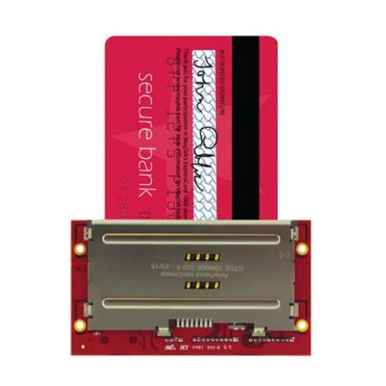
Figure 1-1 – mDynamo Major Components About Terminology In this document, mDynamo is referred to as the device. It is designed to be connected to a host, which is a piece of general-purpose electronic equipment which can send commands and data to, and receive data from, the device. -
Page 11: 1.10 About Solution Planning
Determine what documentation and training will be required from solution design to deployment. Determine what type of host mDynamo will connect to. This can be a computer with a fully-powered USB port. When planning, include any additional support or devices required by the host, such as physical locations, mounting, and power connections. -
Page 12: Electrical Integration
2 - Electrical Integration Electrical Integration Grounding / ESD Protection Figure 2-1 – mDynamo Chassis Ground Points Figure 2-1 shows red highlights on all points on mDynamo that share a common earth ground plane: The four mounting screw pads ... -
Page 13: Shielding
2 - Electrical Integration Shielding MagTek recommends using earth-grounded shielded cables. The device itself has been tested by an FCC lab for Class B radiated susceptibility and has no special shielding requirements. For details, see the FCC information provided at the beginning of this document. -
Page 14: Auxiliary Uart Port [J8]
Programmers should see section 5 Developing Custom Software for cross- references to programming tools and documentation for communicating through the port. mDynamo| EMV Contact Reader / Transaction Hub Module | Installation and Operation Manual Page 14 of 27 (D998200144-14) -
Page 15: Auxiliary Spi Port [J7]
Table 2-1 - Connector Pin Specifications for SPI Device Cable SPI Signal Color Connector Pin BLUE YELLOW BROWN GREEN WHITE BLACK CASE VIOLET mDynamo| EMV Contact Reader / Transaction Hub Module | Installation and Operation Manual Page 15 of 27 (D998200144-14) -
Page 16: External Led Connector [J2]
LED connector, are shown in Figure 2-5. Figure 2-5 – Pinouts and Green LED Reference Implementation for mDynamo LED Connector J2 The connector can drive either an encapsulated red/green three-pin LED with common cathode (allowing for amber blending) or separate red and green LEDs. -
Page 17: Mechanical Integration
Mechanical Integration Figure 3-1 - mDynamo Overall Mechanical Dimensions in Inches [mm] Figure 3-2 - mDynamo Detail Mechanical Dimensions in Inches [mm] mDynamo| EMV Contact Reader / Transaction Hub Module | Installation and Operation Manual Page 17 of 27 (D998200144-14) -
Page 18: Enclosure Design
Figure 3-3 - mDynamo Recommended Orientation On request, MagTek can provide a 3D model of the device’s envelope to assist with the mechanical portion of solution design. MagTek recommends building 3D-printed prototypes with samples before finalizing the solution design. - Page 19 3 - Mechanical Integration Figure 3-4 - Reference Enclosure, Card Slot Width Figure 3-5 - Reference Enclosure, Card Slot Height and Width mDynamo| EMV Contact Reader / Transaction Hub Module | Installation and Operation Manual Page 19 of 27 (D998200144-14)
- Page 20 Connector [J2] and section 4.2 About the General Status LED. If the solution will use Auxiliary SPI Port [J7] or Auxiliary UART Port [J8] to connect mDynamo to external UART or SPI modules, allow space to for the connectors and cables, and consider how the external devices will be mounted relative to the contact chip card insertion slot.
-
Page 21: Cabling Design
For stability, consider using locking connectors when using Auxiliary UART Port [J8], Auxiliary SPI Port [J7], and External LED Connector [J2]. mDynamo| EMV Contact Reader / Transaction Hub Module | Installation and Operation Manual Page 21 of 27 (D998200144-14) -
Page 22: Operation
4 - Operation Operation Before use, make sure mDynamo is connected to a USB host. Generally the host software will always keep a connection open to the device via the USB port, and the device indicates it is ready for a transaction or host command by keeping the General Status LED green. -
Page 23: About The General Status Led
4 - Operation About the General Status LED mDynamo’s on-board General Status LED and the External LED Connector [J2] can be used to provide feedback to operators and cardholders about the internal state of the device (see Figure 1-1). By default, the device drives to match the General Status LED. -
Page 24: Developing Custom Software
FOR MAC OSX In addition to the SDK API libraries, custom software on any operating system can communicate directly with the device using native USB libraries and protocols. For details, see D998200151 MDYNAMO PROGRAMMER'S REFERENCE (COMMANDS). For more information about developing custom applications that integrate with mDynamo, see the MagTek web site or contact your reseller or MagTek Support Services. -
Page 25: Appendix A Technical Specifications
Display Type: Not Applicable Display Size (viewable area): Not Applicable Display Resolution: Not Applicable Keypad: Not Applicable Security Characteristics Tamper Protection: Not Applicable mDynamo| EMV Contact Reader / Transaction Hub Module | Installation and Operation Manual Page 25 of 27 (D998200144-14) - Page 26 5% to 90% non-condensing Storage Temperature: -4°F to 149°F (-20°C to 65°C) Storage Relative Humidity: 5% to 90% non-condensing Vibration Resistance: Not Applicable mDynamo| EMV Contact Reader / Transaction Hub Module | Installation and Operation Manual Page 26 of 27 (D998200144-14)
- Page 27 Magnetic Read Head Life: Not Applicable ICC Read Head Life: 500,000 card insertions Battery Shelf Life: Not Applicable Battery Cycle Life: Not Applicable mDynamo| EMV Contact Reader / Transaction Hub Module | Installation and Operation Manual Page 27 of 27 (D998200144-14)
Need help?
Do you have a question about the mDynamo and is the answer not in the manual?
Questions and answers