Beckhoff AX5000 Series Manuals
Manuals and User Guides for Beckhoff AX5000 Series. We have 6 Beckhoff AX5000 Series manuals available for free PDF download: Function Manual, Manual, Startup Manual, Start-Up, Tuning Manual

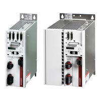
Beckhoff AX5000 Series Function Manual (94 pages)
Brand: Beckhoff
|
Category: Servo Drives
|
Size: 8 MB
Table of Contents
Advertisement
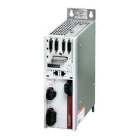
Beckhoff AX5000 Series Startup Manual (46 pages)
Brand: Beckhoff
|
Category: Servo Drives
|
Size: 4 MB
Table of Contents
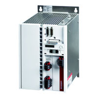
Beckhoff AX5000 Series Start-Up (44 pages)
Servo Drive 1.5 A - 40 A
Brand: Beckhoff
|
Category: Servo Drives
|
Size: 4 MB
Table of Contents
Advertisement
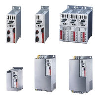
Beckhoff AX5000 Series Manual (49 pages)
Brand: Beckhoff
|
Category: Servo Drives
|
Size: 2 MB
Table of Contents

Beckhoff AX5000 Series Start-Up (40 pages)
Brand: Beckhoff
|
Category: Servo Drives
|
Size: 1 MB
Table of Contents
Beckhoff AX5000 Series Tuning Manual (11 pages)
Brand: Beckhoff
|
Category: Servo Drives
|
Size: 2 MB