Table of Contents
Advertisement
Quick Links
Advertisement
Table of Contents
Troubleshooting

Subscribe to Our Youtube Channel
Related Manuals for IEI Technology PAC-400AI-C236


Summary of Contents for IEI Technology PAC-400AI-C236
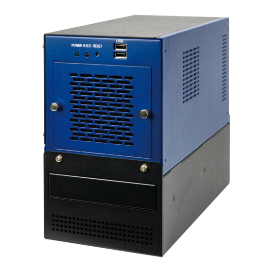
- Page 1 PAC-400AI-C236 Embedded System MODEL: PAC-400AI-C236 ® ® AI System with Intel Xeon E3-1275 v5 CPU, ® Intel C236, DDR4 Memory, Dual GbE, USB 3.2 Gen 1, VGA, PCIe Mini, PCIe x16, PCIe x4, 250W Power Supply, RoHS User Manual Page i...
- Page 2 PAC-400AI-C236 Embedded System Revision Date Version Changes November 26, 2019 1.00 Initial release Page ii...
- Page 3 PAC-400AI-C236 Embedded System Copyright COPYRIGHT NOTICE The information in this document is subject to change without prior notice in order to improve reliability, design and function and does not represent a commitment on the part of the manufacturer. In no event will the manufacturer be liable for direct, indirect, special, incidental, or consequential damages arising out of the use or inability to use the product or documentation, even if advised of the possibility of such damages.
- Page 4 PAC-400AI-C236 Embedded System Manual Conventions WARNING Warnings appear where overlooked details may cause damage to the equipment or result in personal injury. Warnings should be taken seriously. CAUTION Cautionary messages should be heeded to help reduce the chance of losing data or damaging the product.
-
Page 5: Table Of Contents
PAC-400AI-C236 Embedded System Table of Contents 1 INTRODUCTION ......................1 1.1 O ........................2 VERVIEW 1.2 M ....................2 ODEL ARIATIONS 1.3 F ........................3 EATURES 1.4 F ......................3 RONT ANEL 1.5 R ....................... 4 ANEL 1.6 T ..................5... - Page 6 PAC-400AI-C236 Embedded System 4.1 S ................. 31 YSTEM AINTENANCE VERVIEW 4.2 S ..................31 YSTEM ROUBLESHOOTING 4.2.1 The System Doesn’t Turn On ................31 4.2.2 The System Doesn’t Boot Up ................32 4.2.3 More Troubleshooting ..................32 4.3 M ......................33 AINTENANCE 4.3.1 Fan Replacement .....................
- Page 7 PAC-400AI-C236 Embedded System 5.4.1.1 Memory Configuration ................61 5.4.1.2 Graphics Configuration ................62 5.4.1.3 PEG Port Configuration ................64 5.4.2 PCH-IO Configuration ..................66 5.4.2.1 PCI Express Configuration ............... 67 5.4.2.2 SATA Configuration .................. 69 5.4.2.3 HD Audio Configuration ................70 5.5 S...
- Page 8 PAC-400AI-C236 Embedded System List of Figures Figure 1-1: PAC-400AI-C236 Series ....................2 Figure 1-2: Front Panel ........................3 Figure 1-3: Rear Panel ........................4 Figure 1-4: Physical Dimensions (millimeters) ................7 Figure 3-1: Top Cover Removal ....................15 Figure 3-2: Upper Compartment Retention Screws ..............16 Figure 3-3: 3.5"...
- Page 9 PAC-400AI-C236 Embedded System List of Tables Table 1-1: PAC-400AI-C236 Model Variations ................2 Table 1-2: Technical Specifications ....................6 Table 3-1: PCIe Mini Card Slot – Full Size (MSATA1) Pinouts ..........23 Table 3-2: LAN1/LAN2 Pinouts ....................23 Table 3-3: RJ-45 Ethernet Connector LEDs ................24 Table 4-1: Flash Descriptor Security Override Jumper Settings ..........
-
Page 11: Introduction
PAC-400AI-C236 Embedded System Chapter Introduction Page 1... -
Page 12: Overview
It is designed for harsh environment applications, and supports wall mounting method. The PAC-400AI-C236 provides one PCIe x16 slot and one PCIe x4 slot for building AI applications by installing IEI Mustang accelerator cards. Its I/O interfaces include two USB 3.2 Gen 1 ports, two USB 2.0 ports, two GbE, and one VGA. -
Page 13: Features
PAC-400AI-C236 Embedded System 1.3 Features The PAC-400AI-C236 features are listed below: ® ® Intel Xeon E3-1275 v5 CPU (3.60 GHz, quad core, TDP 80W) Supports DDR4 SO-DIMM (system max. 32 GB) Supports one mSATA and one 3.5" SATA HDD ... -
Page 14: Rear Panel
PAC-400AI-C236 Embedded System 1.5 Rear Panel The overview of the rear panel is shown in Figure 1-3 below. Figure 1-3: Rear Panel Page 4... -
Page 15: Technical Specifications
PAC-400AI-C236 Embedded System 1.6 Technical Specifications The PAC-400AI-C236 technical specifications are listed in Table 1-2. System ® ® Intel Xeon E3-1275 v5 CPU (3.60 GHz, quad core, TDP 80W) ® Chipset Intel C236 Memory Two 260-pin 1600/2133 MHz dual-channel DDR4 ECC and non-ECC unbuffered SO-DIMM slots (system max. -
Page 16: Table 1-2: Technical Specifications
PAC-400AI-C236 Embedded System Buttons Power switch Reset button Power Power Input 100 V ~ 240 V AC, 250 W ATX power supply Environmental and Mechanical Mounting Wall mount Thermal 8 cm system fan, CPU fan Operating Temperature 0°C~50°C Storage Temperature 0°C~60°C... -
Page 17: Dimensions
PAC-400AI-C236 Embedded System 1.7 Dimensions The physical dimensions are shown below: Figure 1-4: Physical Dimensions (millimeters) Page 7... -
Page 18: Unpacking
PAC-400AI-C236 Embedded System Chapter Unpacking Page 8... -
Page 19: Anti-Static Precautions
Electrostatic discharge (ESD) can cause serious damage to electronic components, including the PAC-400AI-C236. Dry climates are especially susceptible to ESD. It is therefore critical that whenever the PAC-400AI-C236 or any other electrical component is handled, the following anti-static precautions are strictly adhered to. -
Page 20: Packing List
If some of the components listed in the checklist below are missing, please do not proceed with the installation. Contact the IEI reseller or vendor you purchased the PAC-400AI-C236 from or contact an IEI sales representative directly. To contact an IEI sales representative, please send an email to sales@ieiworld.com. -
Page 21: Optional Items
PAC-400AI-C236 Embedded System 2.4 Optional Items The following table lists the optional items that can be purchased separately. Optional Accelerator card with four Intel® Movidius™ Myriad™ X MA2485 VPUs (P/N: Mustang-V100-MX4-R10) Accelerator card with eight Movidius Myriad X MA2485 VPUs... - Page 22 PAC-400AI-C236 Embedded System Optional SATA power cable (P/N: 32102-000100-200-RS) Audio kit (7.1 Channel) (P/N: AC-KIT-892HD-R10) SATA to IDE/CompactFlash® converter board (P/N: SAIDE-KIT01-R10) Power cable, 100 mm (P/N: 32102-044900-100-RS) Power cable, 150 mm (P/N: 32102-011500-100-RS) CPU cooler (P/N: 19100-000238-00-RS) Page 12...
-
Page 23: Installation
PAC-400AI-C236 Embedded System Chapter Installation Page 13... -
Page 24: Installation Precautions
PAC-400AI-C236. The PAC-400AI-C236’s cooling vents must not be obstructed by any objects. Blocking the vents can cause overheating of the PAC-400AI-C236. Leave at least 5 cm of clearance around the PAC-400AI-C236 to prevent overheating. Grounding: The PAC-400AI-C236 should be properly grounded. The voltage ... -
Page 25: Top Cover Removal
Slide the cover leftwards and then lift the cover up gently. Figure 3-1: Top Cover Removal 3.3 HDD Installation The PAC-400AI-C236 allows installation of one 3.5" HDD/SSD. To install a HDD into the system, please follow the steps below. Step 1: Remove the top cover from the PAC-400AI-C236. -
Page 26: Figure 3-2: Upper Compartment Retention Screws
PAC-400AI-C236 Embedded System Step 2: Remove the upper compartment by removing the four upper compartment retention screws, two from the front and two from the rear of the chassis (Figure 3-3). Figure 3-2: Upper Compartment Retention Screws Step 3: Remove the 3.5" drive bracket by removing the four retention screws from both sides of the drive bracket, two from each side. -
Page 27: Pcie Mini Card Installation (Msata)
Step 6: Connect the HDD power connector and SATA connector. 3.4 PCIe Mini Card Installation (mSATA) The PAC-400AI-C236 has one full-size/half-size PCIe Mini slot on the motherboard. To install a full-size module, follow the instructions below. Step 1: Remove the internal access panel from the PAC-400AI-C236. See Section 3.2. -
Page 28: Figure 3-5: Pcie Mini Slot Location
PAC-400AI-C236 Embedded System Figure 3-5: PCIe Mini Slot Location Step 3: Remove the retention screw as shown in Figure 3-6. Figure 3-6: Removing the Retention Screw Step 4: Line up the notch on the card with the notch on the slot. Slide the PCIe Mini card into the socket at an angle of about 20º... -
Page 29: Figure 3-7: Inserting The Full-Size Pcie Mini Card Into The Slot At An Angle
PAC-400AI-C236 Embedded System Figure 3-7: Inserting the Full-size PCIe Mini Card into the Slot at an Angle Step 5: Secure the full-size PCIe Mini card with the retention screw previously removed (Figure 3-8). Step 0: Figure 3-8: Securing the Full-size PCIe Mini Card... -
Page 30: Half-Size Pcie Mini Card Installation
PAC-400AI-C236 Embedded System 3.4.1 Half-size PCIe Mini Card Installation The PCIe Mini slot (MPCIE1) also allows installation of a half-size PCIe Mini card. To install a half-size PCIe Mini card, please follow the steps below. Step 1: Remove the retention screw as shown in Figure 3-6. -
Page 31: Figure 3-10: Installing The Standoff
PAC-400AI-C236 Embedded System Figure 3-10: Installing the Standoff Step 4: Line up the notch on the card with the notch on the slot. Slide the PCIe Mini card into the slot at an angle of about 20º (Figure 3-11). Figure 3-11: Inserting the Half-size PCIe Mini Card into the Slot at an Angle... -
Page 32: Pcie Mini Card Slot Pinouts - Full/Half Size (Msata1)
PAC-400AI-C236 Embedded System Figure 3-12: Securing the Half-size PCIe Mini Card 3.4.1 PCIe Mini Card Slot Pinouts – Full/Half Size (MSATA1) The MSATA1 slot supports USB 2.0 and mSATA signal for installing mSATA modules. PIN NO. DESCRIPTION PIN NO. DESCRIPTION PCIE_WAKE# +3.3V... -
Page 33: Lan Connection
PAC-400AI-C236 Embedded System PIN NO. DESCRIPTION PIN NO. DESCRIPTION SATA_TX- SMB_DATA SATA_TX+ USB_DATA- USB_DATA+ +3.3V +3.3V +3.3V CLINK_CLK CLINK_DATA 1.5V CLINK_RST# MSATA_DET +3.3V Table 3-1: PCIe Mini Card Slot – Full Size (MSATA1) Pinouts 3.5 LAN Connection The LAN connectors allow connection to an external network. -
Page 34: Mounting The System
Table 3-3: RJ-45 Ethernet Connector LEDs 3.6 Mounting the System Two wall-mount plates are shipped with the PAC-400AI-C236. The wall-mount plates are installed on the sides, at the bottom of the chassis. Each plate is secured to the chassis with three retention screws. To install the wall-mount plates, please follow the steps... -
Page 35: Figure 3-14: Mounting Bracket Retention Screws
PAC-400AI-C236 Embedded System Figure 3-14: Mounting Bracket Retention Screws Step 3: Drill holes in the intended installation surface. Step 4: Align the mounting holes in the sides of the mounting brackets with the predrilled holes in the mounting surface. Step 5: Step 0: Insert retention screws to secure the system to the mounting surface. -
Page 36: Power-On Procedure
3.7.2 Power-on Procedure To power-on the PAC-400AI-C236 please follow the steps below: Step 1: Connect the power source to the power inlet of the PAC-400AI-C236 through the included power cord. Step 2: Press the power button to turn on the system. The power LED on the front panel Step 0: will turn on in green. -
Page 37: Available Drivers
PAC-400AI-C236 Embedded System Figure 3-15: Power-on 3.8 Available Drivers All the drivers for the PAC-400AI-C236 are available on IEI Resource Download Center (https://download.ieiworld.com). Type PAC-400AI-C236 and press Enter to find all the relevant software, utilities, and documentation. Figure 3-16: IEI Resource Download Center... -
Page 38: Driver Download
3.8.1 Driver Download To download drivers from IEI Resource Download Center, follow the steps below. Step 1: Go to https://download.ieiworld.com. Type PAC-400AI-C236 and press Enter. Step 2: All product-related software, utilities, and documentation will be listed. You can choose Driver to filter the result. - Page 39 PAC-400AI-C236 Embedded System NOTE: To install software from the downloaded ISO image file in Windows 8, 8.1 or 10, double-click the ISO file to mount it as a virtual drive to view its content. On Windows 7 system, an additional tool (such as Virtual CD-ROM Control Panel from Microsoft) is needed to mount the file.
-
Page 40: Troubleshooting And Maintenance
PAC-400AI-C236 Embedded System Chapter Troubleshooting and Maintenance Page 30... -
Page 41: System Maintenance Overview
Failure to follow these instructions may lead to personal injury and system damage. To preserve the working integrity of the PAC-400AI-C236 embedded system, the system must be properly maintained. If embedded system components need replacement, the proper maintenance procedures must be followed to ensure the system can continue to operate normally. -
Page 42: The System Doesn't Boot Up
If all troubleshooting measures have been taken and the system still fails to start, contact the IEI reseller or vendor you purchased the PAC-400AI-C236 from or contact an IEI sales representative directly. To contact an IEI sales representative, please send an email to sales@ieiworld.com. -
Page 43: Maintenance
PAC-400AI-C236 Embedded System 4.3 Maintenance 4.3.1 Fan Replacement There is one 8 cm cooling fan inside the PAC-400AI chassis. To replace a fan, please follow the steps below: Step 1: Loosen the two fan filter bracket thumbscrews. Figure 4-1: Fan Filter Bracket Thumbscrews Step 2: Unplug the power cable connected to the fan. -
Page 44: Fan Filter Replacement
Step 0: 4.3.3 Clear CMOS If the PAC-400AI-C236 fails to boot due to improper BIOS settings, the clear CMOS button clears the CMOS data and resets the system BIOS information. To do this, push the clear CMOS button for a few seconds. -
Page 45: Flash Descriptor Security Override Jumper
PAC-400AI-C236 Embedded System Figure 4-3: Clear CMOS Button Location 4.3.4 Flash Descriptor Security Override Jumper The flash descriptor security override jumper (J_FLASH1) allows to enable or disable the ME firmware update. Refer to Table 4-1 and Figure 4-4 for the jumper location and settings. - Page 46 PAC-400AI-C236 Embedded System To update the ME firmware, please follow the steps below. Step 1: Before turning on the system power, short pin 2-3 of the flash descriptor security override jumper. Step 2: Update the BIOS and ME firmware, and then turn off the system power.
-
Page 47: Bios
PAC-400AI-C236 Embedded System Chapter BIOS Page 37... -
Page 48: Introduction
PAC-400AI-C236 Embedded System 5.1 Introduction The BIOS is programmed onto the BIOS chip. The BIOS setup program allows changes to certain system settings. This chapter outlines the options that can be changed. NOTE: Some of the BIOS options may vary throughout the life cycle of the product and are subject to change without prior notice. -
Page 49: Getting Help
PAC-400AI-C236 Embedded System Function Esc key Main Menu – Quit and not save changes into CMOS Status Page Setup Menu and Option Page Setup Menu -- Exit current page and return to Main Menu F1 key General help, only for Status Page Setup Menu and Option... -
Page 50: Main
PAC-400AI-C236 Embedded System 5.2 Main The Main BIOS menu (BIOS Menu 1) appears when the BIOS Setup program is entered. The Main menu gives an overview of the basic system information. Aptio Setup Utility – Copyright (C) 2018 American Megatrends, Inc. -
Page 51: Advanced
PAC-400AI-C236 Embedded System The Main menu has two user configurable fields: System Date [xx/xx/xx] Use the System Date option to set the system date. Manually enter the day, month and year. System Time [xx:xx:xx] Use the System Time option to set the system time. Manually enter the hours, minutes and seconds. -
Page 52: Cpu Configuration
PAC-400AI-C236 Embedded System 5.3.1 CPU Configuration Use the CPU Configuration menu (BIOS Menu 3) to view detailed CPU specifications or enable the Intel Virtualization Technology. Aptio Setup Utility – Copyright (C) 2018 American Megatrends, Inc. Advanced CPU Configuration Number of cores to enable... - Page 53 PAC-400AI-C236 Embedded System Enable all cores in the processor package. EFAULT Enable one core in the processor package. Enable two cores in the processor package. Enable three cores in the processor package. Hyper-threading [Enabled] Use the Hyper-threading BIOS option to enable or disable the Intel Hyper-Threading Technology.
-
Page 54: Pch-Fw Configuration
PAC-400AI-C236 Embedded System 5.3.2 PCH-FW Configuration The PCH-FW Configuration menu (BIOS Menu 4) allows the Intel® AMT options to be configured. Aptio Setup Utility – Copyright (C) 2018 American Megatrends, Inc. Advanced AMT BIOS Features [Enabled] When disabled AMT BIOS... -
Page 55: Acpi Settings
PAC-400AI-C236 Embedded System 5.3.3 ACPI Settings The ACPI Settings menu (BIOS Menu 5) configures the Advanced Configuration and Power Interface (ACPI) options. Aptio Setup Utility – Copyright (C) 2018 American Megatrends, Inc. Advanced ACPI Settings Select the highest ACPI sleep state the system... -
Page 56: F81866 Super Io Configuration
PAC-400AI-C236 Embedded System 5.3.4 F81866 Super IO Configuration Use the F81866 Super IO Configuration menu (BIOS Menu 6) to set or change the configurations for the serial ports and parallel port. Aptio Setup Utility – Copyright (C) 2018 American Megatrends, Inc. -
Page 57: Serial Port N Configuration
PAC-400AI-C236 Embedded System 5.3.4.1 Serial Port n Configuration Use the Serial Port n Configuration menu (BIOS Menu 7) to configure the serial port n. Aptio Setup Utility – Copyright (C) 2018 American Megatrends, Inc. Advanced Serial Port n Configuration Enable or Disable Serial... - Page 58 PAC-400AI-C236 Embedded System IO=2F8h; Serial Port I/O port address is 2F8h and the interrupt IRQ=3, 4, 11 address is IRQ3, 4, 11 IO=3E8h; Serial Port I/O port address is 3E8h and the interrupt IRQ=3, 4, 11 address is IRQ3, 4, 11 ...
-
Page 59: Iwdd H/W Monitor
PAC-400AI-C236 Embedded System IO=2E8h; Serial Port I/O port address is 2E8h and the interrupt IRQ=3, 4, 11 address is IRQ3, 4, 11 Transfer Mode [RS232] The serial port allows setting the data transfer mode to RS-232, RS-422 or RS-485. -
Page 60: Smart Fan Mode Configuration
PAC-400AI-C236 Embedded System CPU_CORE +12V +5VSB +3.3V +3.3VSB 5.3.5.1 Smart Fan Mode Configuration Use the Smart Fan Mode Configuration submenu (BIOS Menu 9) to configure fan speed settings. Aptio Setup Utility – Copyright (C) 2018 American Megatrends, Inc. Advanced Smart Fan Mode Configuration... -
Page 61: Rtc Wake Settings
PAC-400AI-C236 Embedded System Auto mode fan start/off temperature Use the + or – key to change the Auto mode fan start/off temperature value. Enter a decimal number between 1 and 100. Auto mode fan start PWM Use the + or – key to change the Auto mode fan start PWM value. Enter a decimal number between 1 and 100. -
Page 62: Serial Port Console Redirection
PAC-400AI-C236 Embedded System Disabled The real time clock (RTC) cannot generate a wake EFAULT event. Enabled If selected, the Wake up every day option appears allowing you to enable to disable the system to wake every day at the specified time. Besides, the... - Page 63 PAC-400AI-C236 Embedded System Console Redirection [Disabled] Use Console Redirection option to enable or disable the console redirection function. Disabled Disabled the console redirection function EFAULT Enabled Enabled the console redirection function The following options are available in the Console Redirection Settings submenu when the Console Redirection option is enabled.
- Page 64 PAC-400AI-C236 Embedded System Parity [None] Use the Parity option to specify the parity bit that can be sent with the data bits for detecting the transmission errors. None No parity bit is sent with the data bits. EFAULT ...
-
Page 65: Legacy Console Redirection Settings
PAC-400AI-C236 Embedded System 5.3.7.1 Legacy Console Redirection Settings Aptio Setup Utility – Copyright (C) 2018 American Megatrends, Inc. Advanced Legacy Serial Redirection Port [COM1] Select a COM port to display redirection of Legacy OS and Legacy OPROM Messages. --------------------- : Select Screen ↑... -
Page 66: Nvme Configuration
PAC-400AI-C236 Embedded System 5.3.8 NVMe Configuration Use the NVMe Configuration (BIOS Menu 13) menu to display the NVMe controller and device information. Aptio Setup Utility – Copyright (C) 2018 American Megatrends, Inc. Advanced NVMe controller and Drive information No NVMe Device Found --------------------- : Select Screen... -
Page 67: Usb Configuration
PAC-400AI-C236 Embedded System 5.3.9 USB Configuration Use the USB Configuration menu (BIOS Menu 14) to read USB configuration information and configure the USB settings. Aptio Setup Utility – Copyright (C) 2018 American Megatrends, Inc. Advanced USB Configuration Enables Legacy USB support. -
Page 68: Iei Feature
PAC-400AI-C236 Embedded System 5.3.10 iEi Feature Use the iEi Feature menu (BIOS Menu 15) to configure One Key Recovery function. Aptio Setup Utility – Copyright (C) 2018 American Megatrends, Inc. Advanced iEi Feature Auto Recovery Function Reboot and recover Auto Recovery Function... -
Page 69: Chipset
PAC-400AI-C236 Embedded System 5.4 Chipset Use the Chipset menu (BIOS Menu 16) to access the PCH IO and System Agent (SA) configuration menus. WARNING! Setting the wrong values for the Chipset BIOS selections in the Chipset BIOS menu may cause the system to malfunction. -
Page 70: System Agent (Sa) Configuration
PAC-400AI-C236 Embedded System 5.4.1 System Agent (SA) Configuration Use the System Agent (SA) Configuration menu (BIOS Menu 17) to configure the System Agent (SA) parameters. Aptio Setup Utility – Copyright (C) 2018 American Megatrends, Inc. Chipset VT-d Supported VT-d capability... -
Page 71: Memory Configuration
PAC-400AI-C236 Embedded System 5.4.1.1 Memory Configuration Use the Memory Configuration submenu (BIOS Menu 18) to view memory information. Aptio Setup Utility – Copyright (C) 2018 American Megatrends, Inc. Chipset Memory Configuration CHA_DIMM0# Populated & Enabled Size 4096 MB (DDR4) --------------------- Number of Ranks : Select Screen... -
Page 72: Graphics Configuration
PAC-400AI-C236 Embedded System 5.4.1.2 Graphics Configuration Use the Graphics Configuration (BIOS Menu 19) menu to configure the video device connected to the system. Aptio Setup Utility – Copyright (C) 2018 American Megatrends, Inc. Chipset Graphics Configuration Keep IGFX enabled based on the setup options. - Page 73 PAC-400AI-C236 Embedded System Default DVMT Total Gfx Mem [MAX] Use the DVMT Total Gfx Mem option to select DVMT5.0 total graphic memory size used by the internal graphic device. The following options are available: 128M 256M ...
-
Page 74: Peg Port Configuration
PAC-400AI-C236 Embedded System 5.4.1.3 PEG Port Configuration Aptio Setup Utility – Copyright (C) 2018 American Megatrends, Inc. Chipset PEG Port Configuration Select PEG Port Link Width as x16 or 2x8 PEG Link Width Configuration [1 x16] configuration. PEG 0:1:0 Not Present... - Page 75 PAC-400AI-C236 Embedded System Max Link Speed [Auto] Use the Max Link Speed option to select the maximum link speed of the PCI Express slot. The following options are available: Default Auto Gen1 Gen2 Gen3 Detect Non-Compliance Device [Disabled] ...
-
Page 76: Pch-Io Configuration
PAC-400AI-C236 Embedded System 5.4.2 PCH-IO Configuration Use the PCH-IO Configuration menu (BIOS Menu 21) to configure the PCH parameters. Aptio Setup Utility – Copyright (C) 2018 American Megatrends, Inc. Chipset Auto Power Button Status [Disable (ATX)] Select AC power state... -
Page 77: Pci Express Configuration
PAC-400AI-C236 Embedded System USB Power SW1 [+5V DUAL] Use the USB Power SW1 BIOS option to configure whether to provide power to the two external USB 3.0 connectors when the system is in S3/S4 sleep state. This option is valid only when the above Power Saving Function (ERP) BIOS option is disabled. - Page 78 PAC-400AI-C236 Embedded System 5.4.2.1.1 PCI Express Port 1 Aptio Setup Utility – Copyright (C) 2018 American Megatrends, Inc. Chipset PCIe Speed [Auto] Select PCI Express port Detect Non-Compliance Device [Disabled] speed. --------------------- : Select Screen ↑ ↓: Select Item Enter: Select +/-: Change Opt.
-
Page 79: Sata Configuration
PAC-400AI-C236 Embedded System 5.4.2.2 SATA Configuration Use the SATA Configuration menu (BIOS Menu 24) to change and/or set the configuration of the SATA devices installed in the system. Aptio Setup Utility – Copyright (C) 2018 American Megatrends, Inc. Advanced Chipset... -
Page 80: Hd Audio Configuration
PAC-400AI-C236 Embedded System Hot Plug [Disabled] Use the Hot Plug option to designate the correspondent SATA port as hot-pluggable. Disabled Disables the hot-pluggable function of the SATA port. EFAULT Enabled Designates the SATA port as hot-pluggable. 5.4.2.3 HD Audio Configuration Use the HD Audio Configuration menu (BIOS Menu 25) to configure the PCH Azalia settings. -
Page 81: Security
PAC-400AI-C236 Embedded System Auto The onboard High Definition Audio controller EFAULT automatically detected and enabled 5.5 Security Use the Security menu (BIOS Menu 26) to set system and user passwords. Aptio Setup Utility – Copyright (C) 2018 American Megatrends, Inc. -
Page 82: Boot
PAC-400AI-C236 Embedded System 5.6 Boot Use the Boot menu (BIOS Menu 27) to configure system boot options. Aptio Setup Utility – Copyright (C) 2018 American Megatrends, Inc. Main Advanced Chipset Security Boot Save & Exit Boot Configuration Select the keyboard... - Page 83 PAC-400AI-C236 Embedded System Quiet Boot [Enabled] Use the Quiet Boot BIOS option to select the screen display when the system boots. Disabled Normal POST messages displayed Enabled OEM Logo displayed instead of POST messages EFAULT Launch PXE OpROM [Disabled] ...
-
Page 84: Save & Exit
PAC-400AI-C236 Embedded System 5.7 Save & Exit Use the Safe & Exit menu (BIOS Menu 28) to load default BIOS values, optimal failsafe values and to save configuration changes. Aptio Setup Utility – Copyright (C) 2018 American Megatrends, Inc. Main... -
Page 85: Interface Connectors
PAC-400AI-C236 Embedded System Chapter Interface Connectors Page 75... -
Page 86: Peripheral Interface Connectors
PAC-400AI-C236 Embedded System 6.1 Peripheral Interface Connectors The connector locations of the system motherboard (HPCIE-C236) are shown in Table 6-1. Figure 6-1: Main Board Layout Diagram (Front Side) Page 76... -
Page 87: Internal Peripheral Connectors
PAC-400AI-C236 Embedded System 6.2 Internal Peripheral Connectors Internal peripheral connectors on the motherboard and are only accessible when the motherboard is outside of the chassis. The table below shows a list of the connectors on the motherboard. Connector Type Label... -
Page 88: Panel Connectors
PAC-400AI-C236 Embedded System Connector Type Label USB 2.0 connectors 8-pin header USB1, USB2 Table 6-1: Peripheral Interface Connectors 6.3 External Interface Panel Connectors The table below lists the connectors on the external I/O panel. Connector Type Label Ethernet ports RJ-45 LAN1, LAN2 USB 3.0 ports... -
Page 89: A Regulatory Compliance
PAC-400AI-C236 Embedded System Appendix Regulatory Compliance Page 79... - Page 90 PAC-400AI-C236 Embedded System DECLARATION OF CONFORMITY This equipment is in conformity with the following EU directives: EMC Directive 2014/30/EU Low-Voltage Directive 2014/35/EU RoHS II Directive 2011/65/EU, 2015/863/EU If the user modifies and/or install other devices in the equipment, the CE conformity declaration may no longer apply.
- Page 91 PAC-400AI-C236 Embedded System Español [Spanish] IEI Integration Corp declara que el equipo cumple con los requisitos esenciales y cualesquiera otras disposiciones aplicables o exigibles de la Directiva 1999/5/CE. Ελληνική [Greek] IEI Integration Corp ΔΗΛΩΝΕΙ ΟΤΙ ΕΞΟΠΛΙΣΜΟΣ ΣΥΜΜΟΡΦΩΝΕΤΑΙ ΠΡΟΣ ΤΙΣ ΟΥΣΙΩΔΕΙΣ ΑΠΑΙΤΗΣΕΙΣ ΚΑΙ ΤΙΣ ΛΟΙΠΕΣ ΣΧΕΤΙΚΕΣ ΔΙΑΤΑΞΕΙΣ ΤΗΣ ΟΔΗΓΙΑΣ...
- Page 92 PAC-400AI-C236 Embedded System Româna [Romanian] IEI Integration Corp declară că acest echipament este in conformitate cu cerinţele esenţiale şi cu celelalte prevederi relevante ale Directivei 1999/5/CE. Slovensko [Slovenian] IEI Integration Corp izjavlja, da je ta opreme v skladu z bistvenimi zahtevami in ostalimi relevantnimi določili direktive 1999/5/ES.
- Page 93 PAC-400AI-C236 Embedded System FCC WARNING This equipment complies with Part 15 of the FCC Rules. Operation is subject to the following two conditions: This device may not cause harmful interference, and This device must accept any interference received, including interference that ...
-
Page 94: B Safety Precautions
PAC-400AI-C236 Embedded System Appendix Safety Precautions Page 84... -
Page 95: Safety Precautions
PAC-400AI-C236 Embedded System B.1 Safety Precautions WARNING: The precautions outlined in this appendix should be strictly followed. Failure to follow these precautions may result in permanent damage to the PAC-400AI-C236. Please follow the safety precautions outlined in the sections that follow: B.1.1 General Safety Precautions... -
Page 96: Anti-Static Precautions
Electrostatic discharge (ESD) can cause serious damage to electronic components, including the PAC-400AI-C236. Dry climates are especially susceptible to ESD. It is therefore critical that whenever the PAC-400AI-C236 is opened and any of the electrical components are handled, the following anti-static precautions are strictly adhered to. -
Page 97: Product Disposal
PAC-400AI-C236 Embedded System B.1.4 Product Disposal CAUTION: Risk of explosion if the battery is replaced by an incorrect type; Replacement of a battery with an incorrect type that can defeat a safeguard (for example, in the case of some lithium battery types);... -
Page 98: Maintenance And Cleaning Precautions
In such case, the product will be explicitly mentioned in the cleaning tips. Below is a list of items to use when cleaning the PAC-400AI-C236. Cloth – Although paper towels or tissues can be used, a soft, clean piece of ... - Page 99 PAC-400AI-C236 Embedded System Swabs - Swaps moistened with rubbing alcohol or water are excellent tools for wiping hard to reach areas. Whenever possible, it is best to use lint free swabs such as foam swabs for cleaning. Page 89...
-
Page 100: C Digital I/O Interface
PAC-400AI-C236 Embedded System Appendix Digital I/O Interface Page 90... - Page 101 PAC-400AI-C236 Embedded System The DIO connector on the PAC-400AI-C236 is interfaced to GPIO ports on the Super I/O chipset. The DIO has both 8-bit digital inputs and 8-bit digital outputs. The digital inputs and digital outputs are generally control signals that control the on/off circuit of external devices or TTL devices.
- Page 102 PAC-400AI-C236 Embedded System AH – 6FH Sub-function: AL – 9 :Set the digital port as OUTPUT :Digital I/O output value Assembly Language Sample 2 AX, 6F09H ;setting the digital port as output BL, 09H ;digital value is 09H Digital Output is 1001b...
-
Page 103: D Watchdog Timer
PAC-400AI-C236 Embedded System Appendix Watchdog Timer Page 93... - Page 104 PAC-400AI-C236 Embedded System NOTE: The following discussion applies to DOS. Contact IEI support or visit the IEI website for drivers for other operating systems. The Watchdog Timer is a hardware-based timer that attempts to restart the system when it stops working. The system may stop working because of external EMI or software bugs.
- Page 105 PAC-400AI-C236 Embedded System NOTE: The Watchdog Timer is activated through software. The software application that activates the Watchdog Timer must also deactivate it when closed. If the Watchdog Timer is not deactivated, the system will automatically restart after the Timer has finished its countdown.
-
Page 106: E Error Beep Code
PAC-400AI-C236 Embedded System Appendix Error Beep Code Page 96... -
Page 107: Pei Beep Codes
PAC-400AI-C236 Embedded System E.1 PEI Beep Codes Number of Beeps Description Memory not Installed Memory was installed twice (InstallPeiMemory routine in PEI Core called twice) Recovery started DXEIPL was not found DXE Core Firmware Volume was not found Recovery failed... -
Page 108: F Hazardous Materials Disclosure
PAC-400AI-C236 Embedded System Appendix Hazardous Materials Disclosure Page 98... - Page 109 PAC-400AI-C236 Embedded System The details provided in this appendix are to ensure that the product is compliant with the Peoples Republic of China (China) RoHS standards. The table below acknowledges the presences of small quantities of certain materials in the product, and is applicable to China RoHS only.
- Page 110 PAC-400AI-C236 Embedded System 此附件旨在确保本产品符合中国 RoHS 标准。以下表格标示此产品中某有毒物质的含量符 合中国 RoHS 标准规定的限量要求。 本产品上会附有”环境友好使用期限”的标签,此期限是估算这些物质”不会有泄漏或突变”的 年限。本产品可能包含有较短的环境友好使用期限的可替换元件,像是电池或灯管,这些元 件将会单独标示出来。 部件名称 有毒有害物质或元素 铅 汞 镉 六价铬 多溴联苯 多溴二苯 (Pb) (Hg) (Cd) (CR(VI)) (PBB) 醚 (PBDE) 壳体 显示 印刷电路板 金属螺帽 电缆组装 风扇组装 电力供应组装 电池 O: 表示该有毒有害物质在该部件所有物质材料中的含量均在 SJ/T 11363-2006 (现由 GB/T 26572-2011 取代) 标准规定的限量要求以下。...
Need help?
Do you have a question about the PAC-400AI-C236 and is the answer not in the manual?
Questions and answers