
Related Manuals for Danfoss AK-PC 772A


Summary of Contents for Danfoss AK-PC 772A
- Page 1 User Guide Capacity controller for small CO 2 refrigeration system AK-PC 772A ADAP-KOOL® Refrigeration control systems...
-
Page 2: Table Of Contents
Set control of MT compressors ...........56 General monitoring functions ............109 Set control of LT compressors .............60 Miscellaneous ..................111 Setup control of condenser fans ..........61 Appendix - Alarm texts ...............116 Setup control of high pressure ...........63 Capacity controller RS8HF102 © Danfoss 2017-07 AK-PC 772A... -
Page 3: Introduction
1. Introduction Application AK-PC 772A is complete regulating units for capacity control of compressors and gas cooler in a small CO 2 refrigeration systems. Either as a compressor and condenser control on MT or as a boost- er system. There can be regulated with one parallel compressor. -
Page 4: Principles
A regulation with few connections can If there are many connections one or more exten- Examples be performed with the controller module sion modules have to be mounted alone Capacity controller RS8HF102 © Danfoss 2017-07 AK-PC 772A... - Page 5 Ss, Sd, condenser pressure, con- denser pressure in temperature, gas cooler temperature, etc. A graphical display with control buttons can also be fitted. AK-PC 772A Capacity controller RS8HF102 © Danfoss 2017-07...
- Page 6 If you want to know more about a current alarm you can click on it and obtain an information display on the screen. A corresponding display exists for all earlier alarms. Here you can upload information if you need further details about the alarm history. Capacity controller RS8HF102 © Danfoss 2017-07 AK-PC 772A...
-
Page 7: Design Of A Controller
This section will give you a survey of possible connections plus assistance in selecting the modules required by your actual ap- plication. AK-PC 772A Capacity controller RS8HF102 © Danfoss 2017-07... -
Page 8: Module Survey
Extension module with 2x analog output signals If the row of modules needs to be interrupted due to length or external positioning, a communi- cation module should be used. Capacity controller RS8HF102 © Danfoss 2017-07 AK-PC 772A... - Page 9 Accessories Communication modules for controllers where modules cannot be connected continuously Data communication for external extension AK-CM 102 Communication module modules On the following pages there is data specific to each module. AK-PC 772A Capacity controller RS8HF102 © Danfoss 2017-07...
-
Page 10: Common Data For Modules
UL file number: E166834 for XM and CM-modules UL 873, UL file number: E31024 for PC-modules The mentioned data applies to all modules. If data is specific, this is mentioned together with the module in question. Capacity controller RS8HF102 © Danfoss 2017-07 AK-PC 772A... - Page 11 Modules in the 100-series consist of one module Modules in the 200-series consist of two modules Controllers consist of three modules The length of an aggregate unit = n x 72 + 8 AK-PC 772A Capacity controller RS8HF102 © Danfoss 2017-07...
-
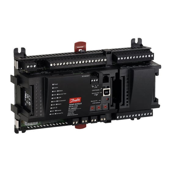
Page 12: Controller
A small module (option board) can be placed on the bottom part • Communication with display on RJ11 plug of the controller. The module is described later in the document. • “Service Pin” switch has been activated Capacity controller RS8HF102 © Danfoss 2017-07 AK-PC 772A... - Page 13 17 (DO6) 42 - 43 - 44 18 (DO7) 45 - 46 - 47 19 (DO8) 48 - 49 - 50 Option Board Please see the signal on the page with the module. AK-PC 772A Capacity controller RS8HF102 © Danfoss 2017-07...
-
Page 14: Extension Module Ak-Xm 101A
5 V output or the 12 V output depending on transmitter type. Light-emitting diodes Only the two top LED’s are used. They indicate the following: • Voltage supply to the module • Communication with the controller is active (red = error) Capacity controller RS8HF102 © Danfoss 2017-07 AK-PC 772A... - Page 15 5 (AI 5) 17 - 18 switch Closed Day/ 6 (AI 6) 19 - 20 Night Open Door 7 (AI 7) 21 - 22 Level switch 8 (AI 8) 23 - 24 AK-PC 772A Capacity controller RS8HF102 © Danfoss 2017-07...
-
Page 16: Extension Module Ak-Xm 102A / Ak-Xm 102B
• Communication with the controller is active (red = error) Off: DI < 2 V a.c. Off: DI < 24 V a.c. • Status of the individual inputs 1 to 8 (when lit = voltage) Capacity controller RS8HF102 © Danfoss 2017-07 AK-PC 772A... - Page 17 5 - 6 4 (DI 4) 7 - 8 5 (DI 5) 9 - 10 6 (DI 6) 11 - 12 7 (DI 7) 13 - 14 8 (DI 8) 15 - 16 AK-PC 772A Capacity controller RS8HF102 © Danfoss 2017-07...
-
Page 18: Extension Module Ak-Xm 103A
Only the two top LED’s are used. They indicate the following: • Voltage supply to the module • Communication with the controller is active (red = error) Max. load I < 2.5 mA R > 4 kΩ Capacity controller RS8HF102 © Danfoss 2017-07 AK-PC 772A... - Page 19 17 - 18 Main switch Closed 6 (AO 2) 19 - 20 Day/ Night Open 7 (AO 3) 21 - 22 Door 8 (AO 4) 23 - 24 Level switch 0-10 V AK-PC 772A Capacity controller RS8HF102 © Danfoss 2017-07...
-
Page 20: Extension Module Ak-Xm 204A / Ak-Xm 204B
Keep the safety distance! Low and high voltage AC-1: max. 4 A (ohmic) must not be connected to AC-15: max. 3 A (Inductive) the same output group AK-XM 204B Override of relay Capacity controller RS8HF102 © Danfoss 2017-07 AK-PC 772A... - Page 21 34 -36 5 (DO 5) 37 - 39 6 (DO 6) 40 - 41 - 42 7 (DO 7) 43 - 44 - 45 8 (DO 8) 46 - 47 - 48 AK-PC 772A Capacity controller RS8HF102 © Danfoss 2017-07...
-
Page 22: Extension Module Ak-Xm 205A / Ak-Xm 205B
AC-1: max. 4 A (ohmic) Behind the upper part there is a fuse for each output. must not be connected to AC-15: max. 3 A (Inductive) the same output group AK-XM 205B Override of relay Capacity controller RS8HF102 © Danfoss 2017-07 AK-PC 772A... - Page 23 13 (DO 5) 37 - 36 - 39 Alarm 14 (DO6) 40 - 41 - 42 Solenoid valve 15 (DO7) 43 - 44 - 45 16 (DO8) 46 - 47 - 48 AK-PC 772A Capacity controller RS8HF102 © Danfoss 2017-07...
-
Page 24: Extension Module Ak-Xm 208C
KVS 15 - KVS 42 Fx: 7.8 + (4 x 5.1) = 28.2 VA AK-PS 150 CCMT 2 - CCMT 8 CCM 10 - CCM 40 CCMT 16 - CCMT 40 5.1 VA Capacity controller RS8HF102 © Danfoss 2017-07 AK-PC 772A... - Page 25 Black Green KVS 42-54 Valve Module Step Terminal 1 (point 9) 25 - 28 2 (point 10) 29 - 32 3 (point 11) 33 - 36 4 (point 12) 37 - 40 AK-PC 772A Capacity controller RS8HF102 © Danfoss 2017-07...
-
Page 26: Extension Module Ak-Ob 110
The two outputs have points 24 and 25. They are shown on the earlier page where the controller is also mentioned. Max. load I < 2.5 mA R > 4 kohm Module Point 0 - 10 V Type Capacity controller RS8HF102 © Danfoss 2017-07 AK-PC 772A... -
Page 27: Extension Module Eka 163B / Eka 164B / Eka 166
Received from the controller via cable. Termination The display must be terminated. Mount a connection between the terminals H and R. (AK-PC 772A is terminated internally.) Placing The display can be placed at a distance of up to 3 m from the controller. -
Page 28: Power Supply Module Ak-Ps 075 / 150 / 250
2.5 A 60 VA Dimension Type High Width AK-PS 075 90 mm 36 mm AK-PS 150 90 mm 54 mm AK-PS 250 90 mm 72 mm Connections AK-PS 075 AK-PS 150 AK-PS 250 Capacity controller RS8HF102 © Danfoss 2017-07 AK-PC 772A... -
Page 29: Communication Module Ak-Cm 102
The controller should permanently be set to = ON. Warning Additional modules may only be installed following the installa- tion of the final module. (Here following module no. 11; see the sketch.) After configuration, the address must not be changed. AK-PC 772A Capacity controller RS8HF102 © Danfoss 2017-07... -
Page 30: Preface To Design
The requirements to the installation are described in a separate Alarm function document. If the alarm is to be sent to a signal transmitter, a relay output will have to be used. Capacity controller RS8HF102 © Danfoss 2017-07 AK-PC 772A... -
Page 31: Connections
✔ The sum of connections cannot exceed 120 (AK-PC 772A). ✔ The number of extension modules must be limited so that the total power in a row will not exceed 32 VA (including control- ler). -
Page 32: Design Of A Compressor And Condenser Control
Speed regulation of 1 or 2 compressors Gas cooler pressure reference Run time equalisation Floating pressure reference Min. restart time Setting of references for heat recovery functions Min. On-time Liquid injection in suction line Capacity controller RS8HF102 © Danfoss 2017-07 AK-PC 772A... -
Page 33: Connections
One extra pressure transmitters can be connected for monitoring and • Sgc (temperature sensor for gas cooling controls) data collection. Shall be placed within one metre after the gas cooler. • Shp (temperature sensor, the refrigerant may be bypassed gas cooler) AK-PC 772A Capacity controller RS8HF102 © Danfoss 2017-07... - Page 34 • SH min = 5°C, SH max = 35°C Gas cooling control: • Fans, speed controlled • Pressure regulation Pgc with reference from Sc3 and Sgc • Pressure increase for heat recovery Capacity controller RS8HF102 © Danfoss 2017-07 AK-PC 772A...
-
Page 35: Planning Table
___ pcs. á 5 VA = __ AK_OB 110 (2 analog outputs) ___ pcs. á 0 VA = 0 1 pcs. á 8 VA = 8 Sum = Sum = max. 32 VA AK-PC 772A Capacity controller RS8HF102 © Danfoss 2017-07... -
Page 36: Length
DIN rail – no matter where in the row the module is found. Removal is likewise carried out with the two catches in the open position. Capacity controller RS8HF102 © Danfoss 2017-07 AK-PC 772A... -
Page 37: Determine The Connection Points
6 (AO 2) 11 - 12 0 - 10 V Speed control, compressor, EC 7 (AO 3) 13 - 14 0 - 10 V 8 (AO 4) 15 - 16 Continued next page AK-PC 772A Capacity controller RS8HF102 © Danfoss 2017-07... -
Page 38: Connection Diagram
Drawings of the individual modules may be pressure signal. ordered from Danfoss. Format = dwg and dxf. You may then yourself write the module number in the circle and draw the individual connections. Capacity controller RS8HF102 © Danfoss 2017-07 AK-PC 772A... - Page 39 Example continued: AK-PC 772A Capacity controller RS8HF102 © Danfoss 2017-07...
-
Page 40: Supply Voltage
+ Separate power supply for the module with the step- per motors: Modules valve control 7.8 VA CCM valve 1.3 VA CCMT valve fx. 5.1 VA ------- Power supply size (least) 14.2 VA Capacity controller RS8HF102 © Danfoss 2017-07 AK-PC 772A... -
Page 41: Ordering
(controller with RJ11 plug) 080G0076 Length = 3 m Accessories Communication modules for controllers where modules cannot be connected continuously AK-CM 102 Communication module Data communication for external extension modules 080Z0064 AK-PC 772A Capacity controller RS8HF102 © Danfoss 2017-07... - Page 42 Capacity controller RS8HF102 © Danfoss 2017-07 AK-PC 772A...
-
Page 43: Mounting And Wiring
We have decided to work on the basis of the example we went through previously, i.e. the following modules: • AK-PC 772A controller module • AK-XM 208C analog input module + stepper output module • AK-XM 103A analog input and output module AK-PC 772A Capacity controller RS8HF102 ©... -
Page 44: Mounting
Lift the top part off the basic module. 2. Mount the extension module in the basic module There are two outputs. 3. Put the top part back on the basic module Capacity controller RS8HF102 © Danfoss 2017-07 AK-PC 772A... -
Page 45: Mounting Of Extension Module On The Basic Module
DIN rail – regard- less of where the module is on the row. Disassembly is thus done with the two snap catches in the open posi- tion. AK-PC 772A Capacity controller RS8HF102 © Danfoss 2017-07... -
Page 46: Wiring
Speed control, compressor LT 6 (AO 2) 11 - 12 0 - 10 V Speed control, compressor, EC 7 (AO 3) 13 - 14 0 - 10 V 8 (AO 4) 15 - 16 Capacity controller RS8HF102 © Danfoss 2017-07 AK-PC 772A... - Page 47 The screen on the pressure transmitter cables must only be connected at the end of the controller. The supply voltage for the pressure transmitter should be taken from the same module that receives the pressure signal. AK-PC 772A Capacity controller RS8HF102 © Danfoss 2017-07...
- Page 48 ■ Service Pin 5. When there is a network Network installation Set the address and activate the Service Pin. Status on output 1-8 6. The controller is now ready to be configured. Capacity controller RS8HF102 © Danfoss 2017-07 AK-PC 772A...
-
Page 49: Configuration And Operation
3 compressors for MT and 2 compressors for LT and high pressure control using heat recovery and gas cooler. The example is shown two pages in. AK-PC 772A Capacity controller RS8HF102 © Danfoss 2017-07... -
Page 50: Configuration
The red alarm bell at the bottom right tells you that there is an active alarm in the controller. In our case the alarm is due to the fact that the time in the controller has not yet been set. Capacity controller RS8HF102 © Danfoss 2017-07 AK-PC 772A... - Page 51 MT & LT compressor group and a high pressure control. The example is the same as the one given in the "Design" section, i.e. the controller is an AK-PC 772A + extension modules. Example Compressor Group MT circuit •...
-
Page 52: Authorization
You will access the login display by pressing the icon at the top left corner of the display. Capacity controller RS8HF102 © Danfoss 2017-07 AK-PC 772A... -
Page 53: Unlock The Configuration Of The Controllers
The values can be changed when it is locked, but only for those settings that do not affect the configuration. 2. Select Lock/Unlock configuration 3. Select Configuration lock Press the blue field with the text Locked 4. Select Unlocked Select Unlocked. AK-PC 772A Capacity controller RS8HF102 © Danfoss 2017-07... -
Page 54: System Setup
This also applies to change-over Daylight saving. Power failure, the clock will be kept running for at least 12 hours. Capacity controller RS8HF102 © Danfoss 2017-07 AK-PC 772A... -
Page 55: Set Plant Type
Fine adjustments can be made if necessary. 5 – Quick relative setup Easy Pgc max. provides a group setting for the overall pressure values. Easy Prec ref. provides a group setting for the receiver controller.. AK-PC 772A Capacity controller RS8HF102 © Danfoss 2017-07... -
Page 56: Set Control Of Mt Compressors
VSD min speed (0.5 – 60.0 Hz) Min. speed where the compressor must cutout VSD start speed (20.0 – 60.0 Hz) Minimum speed for start of Variable speed drive (Must be set higher Capacity controller RS8HF102 © Danfoss 2017-07 AK-PC 772A... - Page 57 The installation is dependent on the combination of com- pressors and coupling pattern. Main step Set the nominal capacity of the main step (Set the percent- age of the relevant compressor’s nominal capacity) 0 - 100%. AK-PC 772A Capacity controller RS8HF102 © Danfoss 2017-07...
- Page 58 - Restart delay Minimum time that a compressor should be OK after a safety cut-out. After this interval it can start again. Capacity controller RS8HF102 © Danfoss 2017-07 AK-PC 772A...
- Page 59 Minimum superheat in suction line SH Max suction line Maximum superheat in suction line AKV period time Periode time for AKV valve Inject delay at start up Delay time for liquid injection at start-up AK-PC 772A Capacity controller RS8HF102 © Danfoss 2017-07...
-
Page 60: Set Control Of Lt Compressors
In principle, the same settings are carried out, but in the LT group it will be possible to select compressors with variable capacity. For the IT group the compressors must be speed controlled. Capacity controller RS8HF102 © Danfoss 2017-07 AK-PC 772A... -
Page 61: Setup Control Of Condenser Fans
Permissible live voltage for EC motor in % (overcapacity) Absolut max Sgc Max value for temperature at Sgc. If the value is exceeded, the EC voltage will be raised to the value in “EC Voltage abs. max. ” Continues AK-PC 772A Capacity controller RS8HF102 © Danfoss 2017-07... - Page 62 Integration time for PI controller Capacity limit at night Setting of maximum capacity limit during night operations. Can be used to limit fan speed at night in order to limit the noise level. Capacity controller RS8HF102 © Danfoss 2017-07 AK-PC 772A...
-
Page 63: Setup Control Of High Pressure
Warning If the regulation is stopped dur- ing high-pressure regulation, the pressure will rise. The system must be dimen- sioned to the higher pressure; otherwise, there will be a loss of charge. AK-PC 772A Capacity controller RS8HF102 © Danfoss 2017-07... -
Page 64: Setup Control Of Receiver Pressure
Vrec IT Comp. Sgc min. The temperature limit for operation with IT compressor. Will not start when a lower value is detected, regardless of the opening degree of the Vrec valve. Capacity controller RS8HF102 © Danfoss 2017-07 AK-PC 772A... -
Page 65: Setup Control Of Heat Recovery
Temperature increase from 50% to 100% in consumer signal Pgc HR min. Pressure value when heat recovery is called for Pgc HR offset Pressure increase from 0 to 50% in consumer signal. AK-PC 772A Capacity controller RS8HF102 © Danfoss 2017-07... -
Page 66: Setup Display
Choose whether readings are to be in SI units (°C and bar) or shown for the individual outputs (US-units °F and psi) In our example, separate displays are not used. The setting is included here for information. Capacity controller RS8HF102 © Danfoss 2017-07 AK-PC 772A... -
Page 67: Setup Functions For General Purpose
1 thermostat so the picture is included for orientation. 1 pressostat 1 voltage signal 10 alarm signals Each function is described on the 1 PI-regulation following pages. AK-PC 772A Capacity controller RS8HF102 © Danfoss 2017-07... -
Page 68: Separate Thermostat
Indicate alarm text for low alarm Separate pressostat 1. Select pressostat 3 - Pressostat Settings as the thermostat In our example, separate pressostat functions are not used. 2. Select actual pressostat 3. Define the required pressostat functions Capacity controller RS8HF102 © Danfoss 2017-07 AK-PC 772A... -
Page 69: Separate Voltage Signal
Set the number of digital alarm inputs has been included for your Adjust for each input information only. • Show on overview • Name • Delay time for DI alarm (common value for all) • Alarm text AK-PC 772A Capacity controller RS8HF102 © Danfoss 2017-07... -
Page 70: Separate Pi Function
• Start up time: Time at startup at which the output signal is force-controlled • Startup output: The output signal size at the startup time. • Stop output signal. Size of the output signal when regula- tion is off. Capacity controller RS8HF102 © Danfoss 2017-07 AK-PC 772A... -
Page 71: Configuration Of Inputs And Outputs
External DI PI-1 as a fault if the signal is interrupted. Press the +-button to go on to the til næste side. AK-PC 772A Capacity controller RS8HF102 © Danfoss 2017-07... - Page 72 Voltage input 1 • 0 -5 V, • 0 -10 V, • 1 – 5 V, • 2 – 10 V PI-in temp PI-ref temp PI- in voltage PI-in pres. PI-ref pres. Capacity controller RS8HF102 © Danfoss 2017-07 AK-PC 772A...
-
Page 73: Set Alarm Priorities
See also alarm text at the end of the manual. In our example we select the settings shown here in the display Press the +-button to go on to the next page 4. Set alarm priorities for condenser AK-PC 772A Capacity controller RS8HF102 © Danfoss 2017-07... - Page 74 Press the +-button to go on to the next page 5. Set alarm priorities for thermostat and extra digital signals In our example we select the settings shown here in the display Capacity controller RS8HF102 © Danfoss 2017-07 AK-PC 772A...
-
Page 75: Lock Configuration
The controller will now make a comparison of selected func- tions and define inputs and outputs. The result can be seen in the next section where the setup is controlled. AK-PC 772A Capacity controller RS8HF102 © Danfoss 2017-07... -
Page 76: Check Configuration
The problem is corrected by setting module number to 0 and point number to 0. Remember that the setup must be unlocked be- fore you can change module and point numbers. Capacity controller RS8HF102 © Danfoss 2017-07 AK-PC 772A... - Page 77 Press the +-button to go on to the next page 6. Check configuration of Analog Inputs The setup of the analog inputs appears as it is supposed to according to the wiring made. AK-PC 772A Capacity controller RS8HF102 © Danfoss 2017-07...
-
Page 78: Check Of Connections
Check that the value of the alarm for the safety monitoring of compres- sor 1 changes to ON. The remaining digital inputs are checked in the same way. Press the +-button to go on to the next page Capacity controller RS8HF102 © Danfoss 2017-07 AK-PC 772A... - Page 79 • The point or module number has not been set up correctly. Press the +-button to go on to the next page • The configuration is not locked. 7. Check Analog inputs AK-PC 772A Capacity controller RS8HF102 © Danfoss 2017-07...
-
Page 80: Check Of Settings
– the ones that can only be seen via the ”Scroll bar”. 4. Check the individual pages The last page contains control data 5. Go back to the overview. Repeat for LT Capacity controller RS8HF102 © Danfoss 2017-07 AK-PC 772A... - Page 81 1 via the "Show in overview display" setting. Check the settings. 11. Then the pressure switch group Check the settings. 12. Proceed with the remaining functions. 13. The controller setup has been completed. AK-PC 772A Capacity controller RS8HF102 © Danfoss 2017-07...
-
Page 82: Schedule Function
3. Setup schedule Press a weekday and set the time for the day period. Continue with the other days. A complete weekly sequence is shown in the display. Capacity controller RS8HF102 © Danfoss 2017-07 AK-PC 772A... -
Page 83: Installation In Network
The wiring has not been carried out correctly. The termination has not been carried out correctly. The data communication requirements are described in the document: ”Data communication connections to ADAP-KOOL® Refrigeration Con- trols” RC8AC. AK-PC 772A Capacity controller RS8HF102 © Danfoss 2017-07... -
Page 84: First Start Of Control
Please note that active plant alarms are automatically cancelled when the main switch is in pos. OFF. If active alarms appear when the control is started the reason for these should be found and remedied. Capacity controller RS8HF102 © Danfoss 2017-07 AK-PC 772A... -
Page 85: Start The Control
The controller will now start controlling the compressors and the fans. Note: Control does not start until both the internal and external switch are “ON”. Any external compressor stop breaker must be ON for the compressors to start. AK-PC 772A Capacity controller RS8HF102 © Danfoss 2017-07... -
Page 86: Manual Capacity Control
See Regulating functions.) Press the blue field against Control mode Select MAN. 4. Set capacity in percent Set the capacity to the required percentage. Press in the blue field against Manual capacity. Press OK. Capacity controller RS8HF102 © Danfoss 2017-07 AK-PC 772A... -
Page 87: Regulating Functions
5. Regulating functions This section describes how the different functions work AK-PC 772A Capacity controller RS8HF102 © Danfoss 2017-07... -
Page 88: Suction Groups
• Internal time schedule The “night displacement” function should not be used when regulation with the override function “P0-optimisation” is performed. (Here the override function will itself adapt the suction pressure to the max. permissible). Capacity controller RS8HF102 © Danfoss 2017-07 AK-PC 772A... -
Page 89: Capacity Control Of Compressors
3 compressor of equal size - The capacity curve will look like this Capacity control AK-PC 772A can control up to 3 compressors on MT and 2 on LT. (For parallel compressor operation, however, the system can only control 2 on MT and 2 on LT.) Each compressor can have up to 3 unloaders. -
Page 90: Capacity Distribution Methods
1.0 - 10.0 1.0-10.0 If a compressor is prevented from starting because it is “hanging” on the restart timer or is safety-cut out, this step is replaced by another compressor or another combination. Capacity controller RS8HF102 © Danfoss 2017-07 AK-PC 772A... -
Page 91: Power Pack Types - Compressor Combinations
Power is connected immediately before the compressor is started. The following is a description of some general rules for handling capacity-regulated compressors, speed-regulated compressors and also for two speed-regulated compressors. AK-PC 772A Capacity controller RS8HF102 © Danfoss 2017-07... - Page 92 The capacity step will now be cut in and the required capacity determined by the controller. The start speed always ought to be set so high that a fast lubrication of the compressor is obtained during the start. Capacity controller RS8HF102 © Danfoss 2017-07 AK-PC 772A...
- Page 93 8) The speed controlled compressor will increase speed until the total capacity reaches 60 kw at max speed 9) When reducing capacity the one step compressors will be cut out when the speed on C1 is at minimum speed. AK-PC 772A Capacity controller RS8HF102 © Danfoss 2017-07...
- Page 94 Afterwards, both compressors will be cut in together and will run operating hours. in parallel. The following one-step compressors will be cut in and out in accordance with the selected coupling pattern. Capacity controller RS8HF102 © Danfoss 2017-07 AK-PC 772A...
-
Page 95: Compressor Timers
The number of relay cutins and cutouts is registered continuously. The number of starts can be read out here: - Number during the previous 24-hour period - Total number since the counter was last set to zero-set. AK-PC 772A Capacity controller RS8HF102 © Danfoss 2017-07... -
Page 96: Compressor With Variable Capacity
The compressor capacity can be controlled from 10 to 67%, depending on the pulse of the unloaders. The relay is then connected to the third unloader. When this relay is on, the capacity will be controlled between 33 and 100%. Capacity controller RS8HF102 © Danfoss 2017-07 AK-PC 772A... -
Page 97: Load Shedding
Alarm: When a load shedding digital inlet is activated, an alarm will be activated to inform that the normal control has been bypassed. This alarm can however be suppressed if so desired. AK-PC 772A Capacity controller RS8HF102 © Danfoss 2017-07... -
Page 98: Liquid Injection In Common Suction Line
The pulse width modulating signal for the AKV valve shall be taken from one of the controller's four solid state outputs. Time delay A time delay can be set which ensures that the injection is delayed during start up. Capacity controller RS8HF102 © Danfoss 2017-07 AK-PC 772A... - Page 99 An alarm limit can be set which will become effective when the suction pressure becomes too high. An alarm will be transmitted when the set time delay has been passed. The regulation continues unchanged. AK-PC 772A Capacity controller RS8HF102 © Danfoss 2017-07...
-
Page 100: Condenser / Gas Cooler
(The maximum value can be overridden by the heat recovery condenser pressure is too high. function). Handling sensor errors: In the event of Sgc failure the controller switches over to an "emergency cooler sequence" that attempts to maintain regula- tion. Capacity controller RS8HF102 © Danfoss 2017-07 AK-PC 772A... - Page 101 The Sgc signal must be stable. If this cannot be done using a sys- tem sensor, it may be necessary to use an immersion tube sensor. If the power supply to AK-PC 772A or the high pressure valve Vhp fails, the system cannot be controlled. We recommend installing an emergency supply (UPS) for both the controller and the valve to avoid faults.
-
Page 102: Heat Recovery
In both cases it applies that when the heat recovery function is de-activated, the reference for the condensing temperature will then decline slowly. Capacity controller RS8HF102 © Danfoss 2017-07 AK-PC 772A... - Page 103 At over 50%, the pressure reference will be “Pgc HR offset”. c. At between 50 and 100%, the fans will be controlled so that the temperature in the gas cooler is increased. Consumer reference Consumer reference Overview AK-PC 772A Capacity controller RS8HF102 © Danfoss 2017-07...
-
Page 104: Capacity Distribution
VLT or a EC motor. In the configuration of the controller’s outputs it will be the output “FanA1”” that will start and stop the frequency converter. Capacity controller RS8HF102 © Danfoss 2017-07 AK-PC 772A... -
Page 105: Condenser Couplings
The ancillary relay outlet is not cut-out. The reason for this is that the fan are often connected in pairs but with one safety circuit. With fault on the one fan, the other will continue to operate. AK-PC 772A Capacity controller RS8HF102 © Danfoss 2017-07... -
Page 106: Circuits For Control Of Co2 Gas Pressure
The current reference can be read from the controller's overview screen. Subcooling It is also possible to configure the subcooling in the sub-critical area.. Capacity controller RS8HF102 © Danfoss 2017-07 AK-PC 772A... -
Page 107: Receiver Control
The setting “delta P MT” will ensure the necessary receiver pressure. AK-PC 772A Capacity controller RS8HF102 © Danfoss 2017-07... -
Page 108: Parallel Compression
P-band. When the capacity requirement of IT decreases and the pressure in the receiver reaches Prec.Min, the compressor will stop and the pressure control will be assumed by the Vrec valve. Capacity controller RS8HF102 © Danfoss 2017-07 AK-PC 772A... -
Page 109: General Monitoring Functions
The PI function is shown overleaf. The individual pressure control function can be adapted to the relevant application as it is possible to give the pressure control a name and indicate alarm texts. AK-PC 772A Capacity controller RS8HF102 © Danfoss 2017-07... - Page 110 - Adjust Kp until the process starts fluctuating and is constantly fluctuating - Adjust Kp to half the value - Adjust Tn down until the process starts fluctuating again - Adjust Tn to double values Capacity controller RS8HF102 © Danfoss 2017-07 AK-PC 772A...
-
Page 111: Miscellaneous
Miscellaneous Supply voltage Sensor calibration: If the power supply to AK-PC 772A or the high pressure valve Vhp The input signal from all connected sensors can be corrected. A fails, the system cannot be controlled. We recommend installing correction will only be necessary if the sensor cable is long and an emergency supply (UPS) for both the controller and the valve has a small cross-sectional area. - Page 112 State a password whether these are correctly attached. c) Select user level d) Select units – either US (e.g. °F and PSI) or Danfoss SI (°C and Note: There is no monitoring when the outlets are overridden. Bar) e) Select language...
- Page 113 MT To evaporating pressure in °C LT To evaporating pressure in °C LT Suction pressure reference LT Set point suction pressure MT Superheat in suction line Sc3 out door temperature in °C AK-PC 772A Capacity controller RS8HF102 © Danfoss 2017-07...
- Page 114 2. Select the "MCX selection" line and press "enter" 3. Select the "Man selection" line and press "enter" 4. The address will be displayed. Check that it is 001, press "enter". Data will then be collected from the controller. Capacity controller RS8HF102 © Danfoss 2017-07 AK-PC 772A...
- Page 115 Stepper Motor Valves Overdrive at Valve Init When selecting a Danfoss stepper motor valve, all settings are fac- During valve initialization, the amount to overdrive the valve, tory set. Here, it is only necessary to select the type of valve.
-
Page 116: Appendix - Alarm Texts
Pc Sensor error High Fan Alarm 1 Fan no. X is reported defective via safety input Fan/VSD safety Medium Fan VSD alarm Variable speed drive for condenser fans has been cut out on safety Capacity controller RS8HF102 © Danfoss 2017-07 AK-PC 772A... - Page 117 The output in question has been put in manual control mode via the AK-ST 500 service tool software Man control ..The output in question has been put in manual control mode via the AK-ST 500 service tool software AK-PC 772A Capacity controller RS8HF102 © Danfoss 2017-07...
- Page 118 Danfoss can accept no responsibility for possible errors in catalogues, brochures and other printed material. Danfoss reserves the right to alter its products without notice. This also applies to products already on order provided that such alternations can be made without subsequential changes being necessary in specifications already agreed.
Need help?
Do you have a question about the AK-PC 772A and is the answer not in the manual?
Questions and answers