
Related Manuals for Danfoss AK-CC 750A


Summary of Contents for Danfoss AK-CC 750A
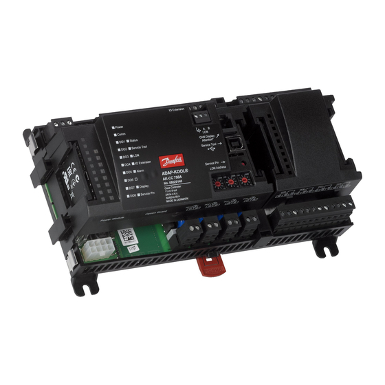
- Page 1 User Guide Controller for evaporator control AK-CC 750A ADAP-KOOL® Refrigeration control systems...
-
Page 2: Table Of Contents
3. Mounting and wiring .............41 Information ....................95 Mounting ....................42 Alarm texts ....................96 Mounting of extension module on the basic module ..42 Appendix - Recommended connection Group 1 ......98 Wiring ......................43 Appendix - Recommended connection Group 2 ......102 RS8HP102 © Danfoss 2018-09 AK-CC 750A... -
Page 3: Introduction
Adaptive defrosting The AK-CC 750A includes an adaptive defrosting function. By using the injection valves opening degree as mass flow sensor for the supply of refrigerant, the controller can monitor ice formation... -
Page 4: Principles
• In addition to the software the top part is provided with connection for data com- munication and address setting. A regulation with few connections can If there are many connections one or more exten- Examples be performed with the controller module sion modules have to be mounted alone RS8HP102 © Danfoss 2018-09 AK-CC 750A... - Page 5 External display An external display can be fitted in order to show the air tempera- tures around the evaporators. In AK-CC 750A up to 4 displays can be mounted. A graphical display with control buttons can also be fitted. AK-CC 750A...
- Page 6 Adaptive defrost AK-CC 750A is equipped with an adaptive defrost function. By using an AKV valve (ETS/CCMT Valve) as mass flow sensor for the supply of refrigerant the control can monitor ice formation on the evaporator.
-
Page 7: Design Of A Controller
If it is an application with many connections it will be necessary to use the controller module plus one or more extension modules. This section will give you a survey of possible connections plus assistance in selecting the modules required by your actual ap- plication. AK-CC 750A RS8HP102 © Danfoss 2018-09... -
Page 8: Module Survey
Controller with analog inputs and relay outputs. The module with additional relay outputs is Top part also available in a version where the top part is provided with change-over switches so that the relays can be overridden. RS8HP102 © Danfoss 2018-09 AK-CC 750A... - Page 9 Length = 1,5 m, 3 m Accessories Communication modules for controllers where modules cannot be connected continuously Data communication for external exten- AK-CM 102 Communication module sion modules On the following pages there is data specific to each module. AK-CC 750A RS8HP102 © Danfoss 2018-09...
-
Page 10: Common Data For Modules
Immunity according to EN 61000-6-2 Emission according to EN 61000-6-3 E31024 for CC-module E357029 for XM and CM-modules The mentioned data applies to all modules. If data is specific, this is mentioned together with the module in question. RS8HP102 © Danfoss 2018-09 AK-CC 750A... - Page 11 The module dimension is 72 mm. Modules in the 100-series consist of one module Modules in the 200-series consist of two modules Controllers consist of three modules The length of an aggregate unit = n x 72 + 8 AK-CC 750A RS8HP102 © Danfoss 2018-09...
-
Page 12: Controller
• Communication on LON • Communication with AK-CM 102 • Alarm when LED flashes - 1 LED that is not used • Communication with display on RJ11 plug • “Service Pin” switch has been activated RS8HP102 © Danfoss 2018-09 AK-CC 750A... - Page 13 42 - 43 - 44 blind Valves 18 (DO7) 45 - 46 - 47 Compres- 19 (DO8) 48 - 49 - 50 Option Board Please see the signal on the page with the module. AK-CC 750A RS8HP102 © Danfoss 2018-09...
-
Page 14: Extension Module Ak-Xm 101A
5 V output or the 12 V output depending on transmitter type. Light-emitting diodes Only the two top LED’s are used. They indicate the following: • Voltage supply to the module • Communication with the controller is active (red = error) RS8HP102 © Danfoss 2018-09 AK-CC 750A... - Page 15 Active at: Ext. Main 5 (AI 5) 17 - 18 Closed switch Day/ 6 (AI 6) 19 - 20 Open Night Door 7 (AI 7) 21 - 22 Defrost 8 (AI 8) 23 - 24 AK-CC 750A RS8HP102 © Danfoss 2018-09...
-
Page 16: Extension Module Ak-Xm 102A / Ak-Xm 102B
• Communication with the controller is active (red = error) Off: DI < 2 V a.c./d.c. Off: DI < 24 V a.c. • Status of the individual inputs 1 to 8 (when lit = voltage) RS8HP102 © Danfoss 2018-09 AK-CC 750A... - Page 17 3 (DI 3) 5 - 6 4 (DI 4) 7 - 8 5 (DI 5) 9 - 10 6 (DI 6) 11 - 12 7 (DI 7) 13 - 14 8 (DI 8) 15 - 16 AK-CC 750A RS8HP102 © Danfoss 2018-09...
-
Page 18: Extension Module Ak-Xm 103A
Only the two top LED’s are used. They indicate the following: • Voltage supply to the module • Communication with the controller is active (red = error) Max. load I < 2.5 mA R > 4 kΩ RS8HP102 © Danfoss 2018-09 AK-CC 750A... - Page 19 5 (AO 1) 17 - 18 Main switch Closed 6 (AO 2) 19 - 20 Day/ Night Open 7 (AO 3) 21 - 22 Door 8 (AO 4) 23 - 24 Level switch 0-10 V AK-CC 750A RS8HP102 © Danfoss 2018-09...
-
Page 20: Extension Module Ak-Xm 204A / Ak-Xm 204B
Behind the upper part there is a fuse for each output. AC-1: max. 4 A (ohmic) must not be connected to the same output group AC-15: max. 3 A (Inductive) AK-XM 204B Override of relay RS8HP102 © Danfoss 2018-09 AK-CC 750A... - Page 21 4 (DO 4) 34 -36 5 (DO 5) 37 - 39 6 (DO 6) 40 - 41 - 42 7 (DO 7) 43 - 44 - 45 8 (DO 8) 46 - 47 - 48 AK-CC 750A RS8HP102 © Danfoss 2018-09...
-
Page 22: Extension Module Ak-Xm 205A / Ak-Xm 205B
AC-1: max. 4 A (ohmic) Behind the upper part there is a fuse for each output. must not be connected to AC-15: max. 3 A (Inductive) the same output group AK-XM 205B Override of relay RS8HP102 © Danfoss 2018-09 AK-CC 750A... - Page 23 13 (DO 5) 37 - 36 - 39 Defrost 14 (DO6) 40 - 41 - 42 Night blind 15 (DO7) 43 - 44 - 45 Valve Compr. 16 (DO8) 46 - 47 - 48 AK-CC 750A RS8HP102 © Danfoss 2018-09...
-
Page 24: Extension Module Ak-Xm 208C
KVS 15 - KVS 42 Fx: 7.8 + (4 x 5.1) = 28.2 VA AK-PS 150 CCMT 2 - CCMT 8 CCM 10 - CCM 40 CTR 20 CCMT 16 - CCMT 42 5.1 VA RS8HP102 © Danfoss 2018-09 AK-CC 750A... - Page 25 CCM / CCMT White Black Green CCMT Valve Module Step Terminal 1 (point 9) 25 - 28 2 (point 10) 29 - 32 3 (point 11) 33 - 36 4 (point 12) 37 - 40 AK-CC 750A RS8HP102 © Danfoss 2018-09...
-
Page 26: Extension Module Ak-Ob 110
The outlets AO1 and AO2 are galvanically separated from the controller module, but not from each other. Max. load I < 2.5 mA R > 4 kohm Module Point 0 - 10 V Type RS8HP102 © Danfoss 2018-09 AK-CC 750A... -
Page 27: Display Module Eka 163B / Eka 164B
Received from the controller via cable and RJ11 connector. Termination The display must be terminated. Mount a connection between the terminals H and R. (AK-CC 750A is terminated internally.) Placing The display can be placed at a distance of up to 3 m from the controller. -
Page 28: Power Supply Module Ak-Ps 075 / 150
AK-PS 150 24 V d.c. 1.5 A 36 VA (adjustable) Connections Dimension Type High Width AK-PS 075 90 mm 36 mm AK-PS 150 90 mm 54 mm Supply to a controller AK-PS 075 AK-PS 150 RS8HP102 © Danfoss 2018-09 AK-CC 750A... -
Page 29: Communication Module Ak-Cm 102
The controller should permanently be set to = ON. Warning Additional modules may only be installed following the installa- tion of the final module. (Here following module no. 11; see the sketch.) After configuration, the address must not be changed. AK-CC 750A RS8HP102 © Danfoss 2018-09... -
Page 30: Preface To Design
Alarm function The requirements to the installation are described in a separate If the alarm is to be sent to a signal transmitter, a relay output will document. Literature number RC8AC. have to be used. RS8HP102 © Danfoss 2018-09 AK-CC 750A... -
Page 31: Connections
(If one controller is switched off, the sig- nal will be pulled down, and all the other controllers will receive a signal which is too low) AK-CC 750A RS8HP102 © Danfoss 2018-09... -
Page 32: Design Of A Evaporator Control
Rail heat control (pulsation) Compressor control. Relay active when refrigeration is demanded Appliance cleaning function Appliance shut down Door contact function Light function Night blind Forced closing Alarm output Start / stop of regulation RS8HP102 © Danfoss 2018-09 AK-CC 750A... - Page 33 Changeover between two thermostat references The function is used for appliances where contents are frequently changed and where a different thermostat reference is required. Changeover between the two references can take place by means of a switch function. AK-CC 750A RS8HP102 © Danfoss 2018-09...
-
Page 34: Connections
Data from this example is used in the planning table on the next page. The result is that the following modules should be used: • AK-CC 750A controller • AK-XM 101A • 3 pcs. EKA 163B If the result had demonstrated that an additional output was needed, AK-XM 205A or B would have been the required exten- sion. -
Page 35: Planning Table
AK-XM 208C (8 analog inputs + 4 stepper outputs) ___ pcs. á 5 VA = __ AK-OB 110 (2 analog outputs) ___ pcs. á 0 VA = 0 1 pcs. á 8 VA = 8 Sum = Sum = max. 32 VA AK-CC 750A RS8HP102 © Danfoss 2018-09... -
Page 36: Length
DIN rail – no matter where in the row the module is found. Removal is likewise carried out with the two catches in the open position. RS8HP102 © Danfoss 2018-09 AK-CC 750A... -
Page 37: Determine The Connection Points
14 (DO 3) 35 - 36 AKV C 15 (DO 4) 37 - 38 Fans 16 (DO 5) 39-40-41 Defrost A 17 (DO6) 42-43-44 Defrost B 18 (DO7) 45-46-47 Defrost C 19 (DO8) 48-49-50 Rail heat AK-CC 750A RS8HP102 © Danfoss 2018-09... -
Page 38: Connection Diagram
Connection diagram Drawings of the individual modules may be ordered from Danfoss. Format = dwg and dxf. You may then yourself write the module number in the circle and draw the individual connections. Example continued: RS8HP102 © Danfoss 2018-09 AK-CC 750A... -
Page 39: Supply Voltage
Example continued: Controller module 8 VA + 1 extension module in 100-series 2 VA ------ Transformer size (least) 10 VA AK-CC 750A RS8HP102 © Danfoss 2018-09... -
Page 40: Ordering
Cable between graphic display type MMIGRS2 and controller (controller with RJ11 plug) 080G0076 Length = 3 m Accessories Communication modules for controllers where modules cannot be connected continuously Data communication for external extension mod- AK-CM 102 Communication module 080Z0064 ules RS8HP102 © Danfoss 2018-09 AK-CC 750A... -
Page 41: Mounting And Wiring
• Is connected We have decided to work on the basis of the example we went through previously, i.e. the following modules: • AK-CC 750A controller module • AK-XM 101A analog output module • 3 pcs. EKA 163B display AK-CC 750A... -
Page 42: Mounting
DIN rail – regard- less of where the module is on the row. Disassembly is thus done with the two snap catches in the open posi- tion. RS8HP102 © Danfoss 2018-09 AK-CC 750A... -
Page 43: Wiring
4 (AI 4) 7 - 8 Case cleaning (pulse pressure) Closed 5 (AI 5) 17 - 18 6 (AI 6) 19 - 20 7 (AI 7) 21 - 22 8 (AI 8) 23 - 24 AK-CC 750A RS8HP102 © Danfoss 2018-09... - Page 44 Constant ON = Active alarm/acknowledged ■ DO7 ■ Display tus" will flash quickly for 10 minutes. ■ DO8 ■ Service Pin Network installation 6. The controller is now ready to be configured. Status on output 1-8 RS8HP102 © Danfoss 2018-09 AK-CC 750A...
-
Page 45: Configuration And Operation
This section describes how the controller: • Is configured • Is operated We have decided to work on the basis of the example we went through previously, i.e. a frost appliance with 3 evaporators. The example is shown overleaf. AK-CC 750A RS8HP102 © Danfoss 2018-09... - Page 46 We have decided to describe the setup by means of an example comprising a freezing appliance with 3 evaporators. The example is the same as the one given in the "Design" section, i.e. the controller is an AK-CC 750A + extension modules. Freezing appliance • Refrigerant R134a •...
-
Page 47: Configuration
The red alarm bell at the bottom right tells you that there is an active alarm in the controller. In our case the alarm is due to the fact that the time in the controller has not yet been set. AK-CC 750A RS8HP102 © Danfoss 2018-09... -
Page 48: Authorization
To activate the new settings you must carry out a new login to the con- troller with the new user name and the relevant access code. You will access the login display by pressing the icon at the top left corner of the display. RS8HP102 © Danfoss 2018-09 AK-CC 750A... -
Page 49: Unlock The Configuration Of The Controllers
On. Only when the main switch is set to Off, and regulation 4. Select Unlocked has therefore been stopped, is it possible to set the configuration lock. Select Unlocked and press OK. AK-CC 750A RS8HP102 © Danfoss 2018-09... -
Page 50: System Setup
This also applies to change-over Daylight saving. Power failure, the clock will be kept running for at least 12 hours. RS8HP102 © Danfoss 2018-09 AK-CC 750A... -
Page 51: Set Plant Type
You can obtain these 3 constants from Danfoss. Defrost control Select whether you want the evaporators to regulate with defrost. Defrost type You can select either natural defrost or electrical defrost, hotgas defrost or warm brine defrost. AK-CC 750A RS8HP102 © Danfoss 2018-09... -
Page 52: Definition Of Thermostat
Choose from the following functions: • Disconnected. Liquid flow is not permitted • Liquid flow SH only. Stopped by a signal from the system device. • Liquid flow Common DI. Stopped by a common DI signal RS8HP102 © Danfoss 2018-09 AK-CC 750A... -
Page 53: Definition Of Sections
In our example, the settings are the 5. Define the other sections Low alarm limit 2 same for all 3 sections. Alarm limit for a low product temperature, band 2 Low delay Time delay for a low product temperature alarm AK-CC 750A RS8HP102 © Danfoss 2018-09... -
Page 54: Definition Of Defrost Functions
Set heating time (time from the point at which defrost stops ) Max. Hold time Maximum hold time that the controller will wait for the signal to restart refrigeration (used with coordinated defrost) Show advanced adaptive defrost All settings for this function are expert settings. RS8HP102 © Danfoss 2018-09 AK-CC 750A... -
Page 55: Definition Of Common Functions
Set the minimum time between the compressor stopping and restarting Press the +-button to go on to the Runtime total next page Set any runtime for the compressor Case cleaning Select whether you want an case cleaning function AK-CC 750A RS8HP102 © Danfoss 2018-09... - Page 56 Select whether you want a main switch via a digital input. When the main switch is set to Off, all regulation is stopped, all outputs are set to standby and all alarms are cancelled. RS8HP102 © Danfoss 2018-09 AK-CC 750A...
-
Page 57: Setup General Alarm Inputs
The name of the function can be xx Set the number of digital alarm inputs and the alarm text can be entered Adjust for each input further down the screen). • Name • Delay time for DI alarm • Alarm text AK-CC 750A RS8HP102 © Danfoss 2018-09... -
Page 58: Setup Separate Thermostat Functions
Indicate alarm text for low alarm 3b - Pressostats There are equal settings for up to 5 pressostat functions Via the +- button you can move to similar settings for the pressure control functions. (Not used in the example) RS8HP102 © Danfoss 2018-09 AK-CC 750A... -
Page 59: Setup Separate Voltage Functions
For each voltage input defined the controller will reserve a relay output in the I/O setup. It is not necessary to define this relay if all you require is an alarm message via the data communication. AK-CC 750A RS8HP102 © Danfoss 2018-09... -
Page 60: Configuration Of Inputs And Outputs
0 – 10 V Press the +-button to go on to the 2 – 10 V next page 0 – 5 V 1 – 5V The type of Step valve defi- ned in earlier sectons. RS8HP102 © Danfoss 2018-09 AK-CC 750A... - Page 61 Voltage signals for reference displacement: Ext. Ref. Signal General voltage inputs 1 - 5 Setting: • 0 - 5 V, • 1 - 5 V, • 0 -10 V, • 2 - 10 V AK-CC 750A RS8HP102 © Danfoss 2018-09...
-
Page 62: Set Alarm Priorities
Press the +-button to go on to the next page 4. Set Alarm priorities for sensor error In our example we select the settings shown here in the display Press the +-button to go on to the next page RS8HP102 © Danfoss 2018-09 AK-CC 750A... - Page 63 In our example we select the settings shown here in the display Press the +-button to go on to the next page 6. Set Alarm priorities for General functions There are no general alarms in our example. AK-CC 750A RS8HP102 © Danfoss 2018-09...
-
Page 64: Lock Configuration
The controller will now make a comparison of selected func- tions and define inputs and outputs. The result can be seen in the next section where the setup is controlled. RS8HP102 © Danfoss 2018-09 AK-CC 750A... -
Page 65: Check Configuration
Press the +-button to go on to the next page fore you can change module and point numbers. 5. Check configuration of Analog Outputs The setup of the Analog inputs appears as it is sup- posed to according to the wiring made. AK-CC 750A RS8HP102 © Danfoss 2018-09... -
Page 66: Check Of Connections
In our case we have no value. This may be due to the following: • The sensor has not been connected. • The sensor is short-circuited/interrupted • The point or module number has not been set up correctly. • The configuration is not locked. RS8HP102 © Danfoss 2018-09 AK-CC 750A... -
Page 67: Check Of Settings
Press the blue overview button at the bottom left of the display. 5. Settings for alarm thermostat Remember the settings at the bottom of the pages – the ones that can only be seen via the ”Scroll bar”. ” AK-CC 750A RS8HP102 © Danfoss 2018-09... - Page 68 Remember the settings at the bottom of the pages – the ones that can only be seen via the ”Scroll bar”. 11. Go to defrost schedule Press the schedule button to continue to the defrost schedule RS8HP102 © Danfoss 2018-09 AK-CC 750A...
- Page 69 Press the blue overview button at the bottom left of the display and then on common functions 15. The settings for the common functions Go through the individual functions. 16. The controller setup has been completed. AK-CC 750A RS8HP102 © Danfoss 2018-09...
-
Page 70: Installation In Network
The wiring has not been carried out correctly. The termination has not been carried out correctly. The data communication requirements are described in the document: ”Data communication connections to ADAP-KOOL® Refrigeration Con- trols” RC8AC. RS8HP102 © Danfoss 2018-09 AK-CC 750A... -
Page 71: First Start Of Control
Please note that active plant alarms are automatically cancelled when the main switch is in pos. OFF. If active alarms appear when the control is started the reason for these should be found and remedied. AK-CC 750A RS8HP102 © Danfoss 2018-09... -
Page 72: Start The Control
The controller will now start the controlling when the external function switch is also activated to ON. If you wish to start an extra defrost cycle, it can be done via this display and also from the defrost screen. RS8HP102 © Danfoss 2018-09 AK-CC 750A... -
Page 73: Setup Logs
If a parameter has to be removed from the log collection, you must select the parameter and then press "Arrow left". A LOG CAN ONLY BE DISPLAYED IF: • THE CLOCK HAS BEEN SET AND • THE CONFIGURATION IS LOCKED AK-CC 750A RS8HP102 © Danfoss 2018-09... -
Page 74: Manual Defrost
Manual defrost 1. Go to Configuration menu If you want to carry out manual defrost, proceed as follows. 2. Select defrost 3. Start defrost Activate RS8HP102 © Danfoss 2018-09 AK-CC 750A... -
Page 75: Regulating Functions
5. Regulating functions This section describes how the different functions work AK-CC 750A RS8HP102 © Danfoss 2018-09... -
Page 76: Introduction
Introduction Examples Application AK-CC 750A controllers are complete regulating units which The controller has been designed to control one of the following four plant types. together with valves and sensors constitute complete evaporator controls for refrigeration appliances and freezing rooms within Through the programming you determine which one. -
Page 77: Thermostat Function
A line up of refrigeration appliances which are to be regulated to the same temperature is a typical example. The temperature is controlled according to the ON/OFF principle in accordance with the thermostat settings in section A. AK-CC 750A RS8HP102 © Danfoss 2018-09... - Page 78 2K. (In the case of a smaller difference, load changes could interfere with the modulating thermostat function.) The current load on the appliance can be read off in the form of the valve's opening time as a percentage of the set period. RS8HP102 © Danfoss 2018-09 AK-CC 750A...
- Page 79 S4 value. With a setting of 100%, only the S4 measurement will be used. With a setting of 0%, only S3 will be used. With a value between 0 and 100%, both measure- ments will be used. AK-CC 750A RS8HP102 © Danfoss 2018-09...
- Page 80 S4 ratio will therefore be required. As a rule the S4 share is set at a lower value during the night than during the day. The thermostat reference can be displaced via an external voltage signal which is particularly useful for process cooling. RS8HP102 © Danfoss 2018-09 AK-CC 750A...
-
Page 81: Temperature Alarms
The time delay will apply until the actual air temperature has dropped below the “upper alarm limit”.. Example Thermostat cut-in value OUT: Thermostat cut-out value Lim: Alarm limit for high temperature and low temperature Alarm ceases AK-CC 750A RS8HP102 © Danfoss 2018-09... -
Page 82: Common Functions
The function uses the S5 sensor from section A. The function is not active when refrigeration has stopped. RS8HP102 © Danfoss 2018-09 AK-CC 750A... - Page 83 When the night blind function is used, the thermostat function can control with different weighting between the S3 and S4 sensors. A weighting during day operation and another when the blind is closed. AK-CC 750A RS8HP102 © Danfoss 2018-09...
- Page 84 The function applies to all sections. You can also define an external switch for start/stop of the regula- tion. If an external switch is defined regulation will only be carried out when both switches are in position ”ON”. RS8HP102 © Danfoss 2018-09 AK-CC 750A...
-
Page 85: General Monitoring Functions
Alarm limits can be set for low and high pressure, respectively, including separate alarm delays. The individual pressure control function can be adapted to the relevant application as it is possible to give the pressure control a name and indicate alarm texts. AK-CC 750A RS8HP102 © Danfoss 2018-09... -
Page 86: Liquid Injection
If both a stepper valve and a solenoid valve are installed in the controller will not result in liquid throughput to the compressor. Danfoss accepts no responsibility for damage resulting from liquid line, any liquid trapped between the two valves will be inadequate installation. -
Page 87: Defrost
During warm brine defrost, the solenoid Defrost sequence valve is kept open during defrost so that the warm brine can run Every defrost runs through the following sequence: through the "evaporator". AK-CC 750A RS8HP102 © Danfoss 2018-09... - Page 88 S4 is an air sensor placed in If a signal on forced closing during a defrost is received, the se- the evaporator outlet). lected setting determines whether defrosting is to be stopped. RS8HP102 © Danfoss 2018-09 AK-CC 750A...
- Page 89 The fans are delayed so that the remaining drops of water are bound to the evaporator. The fans start when the re- quired fan start temperature has been reached on the S5 sensor, AK-CC 750A RS8HP102 © Danfoss 2018-09...
- Page 90 R23, R513B, R13B1 or user- defined. This function can only cancel planned defrosts which start from a defrost schedule – either an internal schedule or an external RS8HP102 © Danfoss 2018-09 AK-CC 750A...
- Page 91 This alarm is removed when flash gas disappears or at the start of the next defrost. • Valve The function is suitable for application of a valve from Danfoss. Valves from other manufacturers is not recommended. AK-CC 750A RS8HP102 © Danfoss 2018-09...
-
Page 92: Miscellaneous
The appliance/room controllers can supply the necessary informa- want to set tion to the system unit so that it can optimise the suction pressure 3. Press the centre button to display the value based on the appliance with the heaviest load. RS8HP102 © Danfoss 2018-09 AK-CC 750A... - Page 93 X = When the controller is not set up, the display will only read the marked settings 7. When there is a network: set the address for the address switch in the controller. 8. Send this address to the system unit by activating a service pin. AK-CC 750A RS8HP102 © Danfoss 2018-09...
- Page 94 Stepper Motor Valves AKS 32R info When selecting a Danfoss stepper motor valve, all settings are fac- tory set. Here, it is only necessary to select the type of valve. If a valve from other manufacturers is used the following settings has to be made.
-
Page 95: Information
Electronic controls are no substitute for normal, good engineering practice. Door contact Danfoss will not be responsible for any goods, or plant compo- Door contact status nents, damaged as a result of the above defects. It is the installer’s... -
Page 96: Alarm Texts
The refrigerant setting has been changed leak alarm Refrigerant leak A signal is being received from a leak detector Refrigerant (The alarm relay on AK-CC 750A will not be activated) Case cleaning High Case cleaning initiated A case cleaning has been initiated... - Page 97 There is a communication fault between the controller module and the extension modules – the fault must be cor- rected as soon as possible Manual override IO The input/ output in question has been put in manual control mode via the AK-ST 500 service tool software AK-CC 750A RS8HP102 © Danfoss 2018-09...
-
Page 98: Appendix - Recommended Connection Group 1
Main s. Po AKV A AKV B AKV C AKV D Def. A Def. B Room S2A S3A For. cl. Door Main s. Po AKV A AKV B AKV C AKV D Def. A Def. B RS8HP102 © Danfoss 2018-09 AK-CC 750A... - Page 99 Alarm Light Def. C Rail heat Comp. Fan Alarm Suction Drain Light Alarm Def. C Def. D Rail heat Comp. Fan Alarm Def. C Def. D Rail heat Comp. Fan Alarm Suction Drain Light AK-CC 750A RS8HP102 © Danfoss 2018-09...
- Page 100 AKV A AKV B AKV C AKV D Def. A Def. B S3 + S4 S3A S4A For. cl. Main s. Po AKV A AKV B AKV C AKV D Def. A Def. B RS8HP102 © Danfoss 2018-09 AK-CC 750A...
- Page 101 Def. C Def. D Rail heat Comp. Fan Alarm Light Light Def. C Def. D Rail heat Comp. Fan Alarm Suction Drain Def. C Def. D Rail heat Comp. Fan Alarm Suction Drain Light Blinds AK-CC 750A RS8HP102 © Danfoss 2018-09...
-
Page 102: Appendix - Recommended Connection Group 2
S3A S4A Clean Blinds AKV A AKV B AKV C AKV D Def. A Def. B S3 + S4 S3A S4A Clean Blinds AKV A AKV B AKV C AKV D Def. A Def. B RS8HP102 © Danfoss 2018-09 AK-CC 750A... - Page 103 Drain Light Light Light Light Light Light Light Light Suction Drain Rail heat Light Blinds Light Def. C Def. D Rail heat Light Blinds Def. C Def. D Rail heat Light Blinds Suction Drain AK-CC 750A RS8HP102 © Danfoss 2018-09...
- Page 104 Rail heat S5A S4B Clean Blinds LLSV A LLSV B LLSV C LLSV D Def. A Def. B S5A S4B Clean Blinds LLSV A LLSV B LLSV C LLSV D Def. A Def. B RS8HP102 © Danfoss 2018-09 AK-CC 750A...
- Page 105 Suction Drain Light Light Light Light Light Light Light Light Suction Drain Rail heat Light Light Def. C Def. D Rail heat Light Blinds Def. C Def. D Rail heat Light Blinds Suction Drain AK-CC 750A RS8HP102 © Danfoss 2018-09...
- Page 106 Danfoss can accept no responsibility for possible errors in catalogues, brochures and other printed material. Danfoss reserves the right to alter its products without notice. This also applies to products already on order provided that such alternations can be made without subsequential changes being necessary in specifications already agreed.
Need help?
Do you have a question about the AK-CC 750A and is the answer not in the manual?
Questions and answers