Table of Contents
Advertisement
Quick Links
Advertisement
Table of Contents

Related Manuals for SPHINX Project Eighteen


Summary of Contents for SPHINX Project Eighteen
- Page 1 SERVICE MANUAL PROJECT EIGHTEEN TRUE DUAL MONO POWER AMPLIFIER...
-
Page 2: Table Of Contents
SPHINX Project Eighteen Service Manual 1. UNPACKING ............................3 2. SPHINX WARRANTY CARD ......................3 3. CONTACTING THE MANUFACTURER .....................3 4. THE POWER AMP AT A GLANCE.....................4 Front panel..............................4 Rear panel ..............................5 5. TECHNICAL SPECIFICATIONS ......................6 6. GENERAL CHECKLIST........................7 Optical connections ............................. 7 Switching the amp on........................... -
Page 3: Unpacking
In case of any problem not covered in this manual All of this means that the Project Eighteen can work or if you have other questions you may contact the with all kind of loads from every loudspeaker: even... -
Page 4: The Power Amp At A Glance
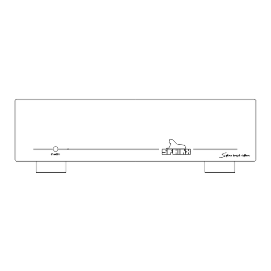
SPHINX Project Eighteen Service Manual 4. THE POWER AMP AT A GLANCE Front panel 1. LED: Indicates the selected function: stand-by green 2. STANDBY: To switch the component on and off. -
Page 5: Rear Panel
(balanced cable) from the left output of the CONTROL IN: To connect the optical cable signal source. from another Sphinx component like a pre-amp. 10. CONTROL OUT: To connect the optical cable BALANCED RIGHT: To connect the XLR cable going to another Sphinx component. -
Page 6: Technical Specifications
This unit conforms to the EMC interference regulations issued by the EU and to the CE standards. This unit complies with safety regulation VDE 0860 and therefore with international safety regulation IEC 65. Technical specifications may be changed by SPHINX without prior notice if technical developments make this necessary. -
Page 7: General Checklist
SPHINX Project Eighteen Service Manual 6. GENERAL CHECKLIST Before you test or service the Project Eighteen Protection mode please check the following items. They will give If at any time the output DC-offset exceeds 500 mV information about the current status of the amplifier. -
Page 8: Adjustment Procedures
7. ADJUSTMENT PROCEDURES High Bias With this procedure you set the proper bias level for The Project Eighteen has eight adjustable settings, the power transistors. This ensures their Class A meaning four adjustment procedures per channel: operation at low power levels. -
Page 9: Low Bias
SPHINX Project Eighteen Service Manual Low Bias Offset With this procedure you set the proper bias level so The Offset adjustment procedure minimises the DC the power transistors will remain at operating offset value of the amplifier output. This DC offset is temperature during standby mode. -
Page 10: Common Mode
SPHINX Project Eighteen Service Manual Common Mode The Common Mode adjustment procedure minimises the amplification error of the (internal) differential amplifier. If the balanced input amplifier receives an identical signal at the normal (+) and inverted (-) inputs the output signal will be zero. This helps to reduce the... -
Page 11: Problems And Solutions
SPHINX Project Eighteen Service Manual 8. PROBLEMS AND SOLUTIONS Please also send (by fax or e-mail) the specific At the moment of writing the Project Eighteen has information to the Sphinx International Service one known specific problem. Department (see page 3): this info can then be If in the future you encounter any problem(s) you added to the general database to aid others. -
Page 12: Diagrams And Parts Lists
SPHINX Project Eighteen Service Manual 9. DIAGRAMS AND PARTS LISTS The next pages contain a complete set of schematic drawings including the associated parts lists (if applicable). Connecting diagram for testing the project 18 ................... 13 Connection diagram for common mode adjustment .................. 14 Schematic layout of all relevant parts ...................... -
Page 13: Connecting Diagram For Testing The Project 18
SPHINX Project Eighteen Service Manual Connecting diagram for testing the project 18 Project 18 THD ANALYZER SCOOP SWITCH-BOX... -
Page 14: Connection Diagram For Common Mode Adjustment
SPHINX Project Eighteen Service Manual Connection diagram for common mode adjustment Project 18 THD ANALYZER SCOOP SWITCH-BOX... -
Page 15: Schematic Layout Of All Relevant Parts
SPHINX Project Eighteen Service Manual Schematic layout of all relevant parts R481 R281 Source resistor Source resistor R477 R277 Potmeter P401 Potmeter P201 symmetry symmetry Source resistor Source resistor R473 R273 Potmeter P404 Potmeter P204 Source resistor Offset Offset Source resistor... -
Page 16: Schematic Overview Of The Project 18 Mainboard
SPHINX Project Eighteen Service Manual Schematic overview of the Project 18 mainboard 60 x 2200U/63V +60V POWER-RAIL-R F203 CN215 +60V POWER-RAIL-R C237 C222 C223 C224 C225 C226 C227 C228 C229 C230 C231 C232 C233 C234 C235 C236 GROUND POWER-RAIL RIGHT CHANNEL... -
Page 17: Project 18 Logic
SPHINX Project Eighteen Service Manual Project 18 logic D407 IC101 R496 7812 Vout +12V R491 +12V C104 IC401B LEFT DC DETECT R495 100N C106 C266 C466 100K D408 R497 CN104 R492 C464 C465 C268 C468 -12V IC401A R494 C105 R493... -
Page 18: Project 18 Supply & Relay Control Schematic
SPHINX Project Eighteen Service Manual Project 18 supply & relay control schematic R106 CN211 CN101 CN202 CN203 CN201 CN208 CN207 CN205 CN401 CN204 CN407 CN402 CN209 CN212 B101 CN213 CN405 CN403 + C102 CN103 CN408 C35V/1000U CN404 R107 CN214 CN409... -
Page 19: Project 18 Blockdiagram Left
SPHINX Project Eighteen Service Manual Project 18 blockdiagram left R401 +70V STAB-RAIL-L +70V STAB-RAIL-L +70V STAB-RAIL-L 4K75 CN421 +60V POWER-RAIL-L +60V POWER-RAIL-L +60V POWER-RAIL-L R403 INPUT L + INPUT L + OUTPUT RELAIS LEFT OUTPUT RELAIS LEFT project 18 REL401B... -
Page 20: Project 18 Blockdiagram Right
SPHINX Project Eighteen Service Manual Project 18 blockdiagram right R201 +70V STAB-RAIL-R +70V STAB-RAIL-R +70V STAB-RAIL-R 4K75 CN221 +60V POWER-RAIL-R +60V POWER-RAIL-R +60V POWER-RAIL-R R203 INPUT R + INPUT R + OUTPUT RELAIS RIGHT OUTPUT RELAIS RIGHT GROUND GROUND GROUND... -
Page 21: Project 18 Amplifier Diagram Left
SPHINX Project Eighteen Service Manual Project 18 amplifier diagram left T409 C3423 1N4148 R424 C50V/22U +70V STAB-RAIL-L 10R0 + C410 D401 R410 R416 R425 R436 C413 R449 C417 C100V/47U C402 C404 2K21 2K21 6K82 130R 330N/100V LD401 D403 1N4007 T415... -
Page 22: Project 18 Amplifier Diagram Right
SPHINX Project Eighteen Service Manual Project 18 amplifier diagram right T209 C3423 1N4148 R224 C50V/22U +70V STAB-RAIL-R 10R0 + C210 D201 R210 R216 R225 R236 C213 R249 C217 C100V/47U C202 C204 330N/100V 2K21 2K21 6K82 130R LD201 D203 1N4007 T215... -
Page 23: Project 18 Power Supply Left
SPHINX Project Eighteen Service Manual Project 18 power supply left F401 SOLDRED2 T432 A1306 R483 BR401 +70V STAB-RAIL-R 10R0 Z403 C454 C456 C462 R484 C100V/100U 1K00 SOLDYEL2 C460 R485 T433 C2240 68K1 C458 F402 LD407 SOLDBLK2 R489 CN416 BR402 GROUND... -
Page 24: Project 18 Power Supply Right
SPHINX Project Eighteen Service Manual Project 18 power supply right F201 SOLDRED1 T232 A1306 R283 BR201 +70V STAB-RAIL-R C254 C256 10R0 Z203 C262 R284 C100V/100U 1K00 SOLDYEL1 C260 R285 T233 C2240 68K1 C258 F202 LD207 SOLDBLK1 R289 CN216 BR202 GROUND... -
Page 25: Pcb Drawings Of Project 18
SPHINX Project Eighteen Service Manual PCB drawings of Project 18 Because there is a significant image-quality loss during the conversion of the drawing, the PCB-drawing is located in a seperate file. This file is in PDF-format (Adobé Acrobat 3.0 Reader). -
Page 26: Partlist
SPHINX Project Eighteen Service Manual Partlist Designator Part Type Description B101 WO2M Bridge rectifier BR201 KBPC602 Bridge rectifier BR202 KBPC602 Bridge rectifier BR401 KBPC602 Bridge rectifier BR402 KBPC602 Bridge rectifier C100 330uF/50V Electrolytic capacitor C101 10uF/50V Electrolytic capacitor C102 1000uF/35V... - Page 27 SPHINX Project Eighteen Service Manual Designator Part Type Description C229 2200uF/63V Electrolytic capacitor C230 2200uF/63V Electrolytic capacitor C231 2200uF/63V Electrolytic capacitor C232 2200uF/63V Electrolytic capacitor C233 2200uF/63V Electrolytic capacitor C234 2200uF/63V Electrolytic capacitor C235 2200uF/63V Electrolytic capacitor C236 2200uF/63V Electrolytic capacitor...
- Page 28 SPHINX Project Eighteen Service Manual Designator Part Type Description C409 470uF/35V Electrolytic capacitor C410 47uF/100V Electrolytic capacitor C411 47uF/100V Electrolytic capacitor C412 22pF Ceramic capacitor C413 68nF MKT capacitor C414 68nF MKT capacitor C415 220pF Styroflex capacitor C416 68nF MKT capacitor...
- Page 29 SPHINX Project Eighteen Service Manual Designator Part Type Description C458 100uF/25V Electrolytic capacitor C459 100uF/25V Electrolytic capacitor C460 33pF Ceramic capacitor C461 33pF Ceramic capacitor C462 100uF/100V Electrolytic capacitor C463 100uF/100V Electrolytic capacitor C464 MKT capacitor C465 MKT capacitor C466...
- Page 30 SPHINX Project Eighteen Service Manual Designator Part Type Description LD203 LO5R3000F3 LED red LD204 LO5R3000F3 LED red LD205 LO5R3000F3 LED red LD206 LO5R3000F3 LED red LD207 LO5R3000F3 LED red LD208 LO5R3000F3 LED red LD401 LO5R3000F3 LED red LD402 LO5R3000F3 LED red...
- Page 31 SPHINX Project Eighteen Service Manual Designator Part Type Description R201 4K75 Resistor MRS25 R202 316R Resistor MRS25 R203 604R Resistor MRS25 R204 18K2 Resistor MRS25 R205 4K75 Resistor MRS25 R206 604R Resistor MRS25 R207 604R Resistor MRS25 R208 47K5 Resistor MRS25...
- Page 32 SPHINX Project Eighteen Service Manual Designator Part Type Description R250 130R Resistor MRS25 R251 5K62 Resistor MRS25 R252 5K62 Resistor MRS25 R253 47K5 Resistor MRS25 R254 47K5 Resistor MRS25 R255 22R1 Resistor MRS25 R256 22R1 Resistor MRS25 R257 51R1 Resistor MRS25...
- Page 33 SPHINX Project Eighteen Service Manual Designator Part Type Description R401 4K75 Resistor MRS25 R402 316R Resistor MRS25 R403 604R Resistor MRS25 R404 18K2 Resistor MRS25 R405 4K75 Resistor MRS25 R406 604R Resistor MRS25 R407 604R Resistor MRS25 R408 47K5 Resistor MRS25...
- Page 34 SPHINX Project Eighteen Service Manual Designator Part Type Description R450 130R Resistor MRS25 R451 5K62 Resistor MRS25 R452 5K62 Resistor MRS25 R453 47K5 Resistor MRS25 R454 47K5 Resistor MRS25 R455 22R1 Resistor MRS25 R456 22R1 Resistor MRS25 R457 51R1 Resistor MRS25...
- Page 35 SPHINX Project Eighteen Service Manual Designator Part Type Description REL201 RELAY DPDT Relay REL202 RELAY DPDT Relay REL203 RELAY DPDT Relay REL401 RELAY DPDT Relay REL402 RELAY DPDT Relay REL403 RELAY DPDT Relay T100 BDX44 Transistor T101 BC547 Transistor T102...
- Page 36 SPHINX Project Eighteen Service Manual Designator Part Type Description T232 2SA1306 Transistor T233 2SC2240 Transistor T234 2SA970 Transistor T235 2SC3298 Transistor T401 2SA970 Transistor T402 2SC2240 Transistor T403 K389 Dual N-JFET T404 J109 Dual P-JFET T405 2SC2240 Transistor T406 2SA970...
- Page 37 SPHINX Project Eighteen Service Manual Designator Part Type Description Z402 Zener diode Z403 Zener diode Z404 Zener diode ©1998 Audioscript BV Version: 3-09-1998...
Need help?
Do you have a question about the Project Eighteen and is the answer not in the manual?
Questions and answers