Table of Contents
Advertisement
Advertisement
Table of Contents

Related Manuals for SPHINX Project10


Summary of Contents for SPHINX Project10
-
Page 1: Service Manual
SERVICE MANUAL PROJECT TEN INTEGRATED STEREO AMPLIFIER... -
Page 2: Table Of Contents
2. SPHINX WARRANTY CARD......................3 3. CONTACTING THE MANUFACTURER.....................3 4. THE AMP AT A GLANCE ........................4 Front panel..............................4 Rear panel ..............................5 5. SPHINX REMOTE CONTROL ......................6 Buttons and LED indication.......................... 6 Operation ..............................7 Selecting without switching .......................... 7 Batteries............................... 7 Encountering problems... -
Page 3: Unpacking
The Sphinx Project Ten design 1. UNPACKING Before leaving the factory every Project Ten is The Sphinx Project Ten was designed for the ever- subjected to stringent and extensive technical and increasing group of quality-conscious audiophiles. exterior quality inspection. This ensures the user... -
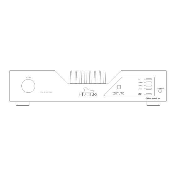
Page 4: The Amp At A Glance
SPHINX Project Ten Service Manual 4. THE AMP AT A GLANCE Front panel 1. VOLUME: With this motor-controlled knob you 2. STANDBY: To switch the component on and off. may adjust the volume of the loudspeakers. When the component is 'off' (standby) this is The volume can be controlled manually or via the indicated by the red LED. -
Page 5: Rear Panel
(balanced cable) from the left output of the signal source for Input 2. 14. CONTROL OUT: To connect the optical cable going to another Sphinx component. 20. CINCH/BALANCED: This switch is to select the input connector for LINE 2: 15. -
Page 6: Sphinx Remote Control
SPHINX Project Ten Service Manual 5. SPHINX REMOTE CONTROL This single Sphinx Remote Control lets you control all functions: not only of the Project Ten, but of all other Sphinx equipment. Only the following buttons and indications on the Remote apply to the Project Ten (the others will not... -
Page 7: Operation
SPHINX Project Ten Service Manual Operation Encountering problems... The Sphinx Remote is used for several different models and can therefore transmit different control codes, depending on which model has been Remote Control does not work selected with the select buttons (1.). -
Page 8: Technical Specifications
This unit conforms to the EMC interference regulations from the EU and to the CE standards. This unit complies with safety regulation VDE 0860 and thus with international safety regulation IEC 65. Technical specifications can be changed by SPHINX without prior notice if technical developments make this necessary. -
Page 9: General Checklist
SPHINX Project Ten Service Manual 7. GENERAL CHECKLIST Necessary Equipment To properly service the Project Ten you need some Before you test or service the Project Ten please specific measurement equipment and use a specific check the following items. They will give information set-up. -
Page 10: Adjustment Procedures
SPHINX Project Ten Service Manual 8. ADJUSTMENT PROCEDURES Bias The Project Ten is an integrated amplifier, meaning With this procedure you set the proper bias level for the pre-amp and power amp sections are combined the power transistors. This ensures their Class A into one cabinet. -
Page 11: Offset
SPHINX Project Ten Service Manual Offset The Offset adjustment procedure minimises the DC offset value of the amplifier output. This DC offset is important when capacitive loads are used, such as electrostatic loudspeakers. These loudspeakers often use a very low-impedance step-up transformer. -
Page 12: Problems And Solutions
9. PROBLEMS AND SOLUTIONS Please also send (by fax or e-mail) the specific At the moment of writing the Project Ten has no information to the Sphinx International Service known specific problems. Department (see page 3): this info can then be If in the future you encounter any problem(s) you added to the general database to aid others. -
Page 13: Diagrams And Parts Lists
SPHINX Project Ten Service Manual 10. DIAGRAMS AND PARTS LISTS The next pages contain the front and rear panel lay-out and a complete set of schematic drawings including the associated parts lists (if applicable). Connection diagram bias adjustment ......................14 Connection diagram offset adjustment .......................15 Connections main board and display board of Project 10 ................16... -
Page 14: Connection Diagram Bias Adjustment
SPHINX Project Ten Service Manual Connection diagram bias adjustment Project 10 THD ANALYZER SWITCH-BOX... -
Page 15: Connection Diagram Offset Adjustment
SPHINX Project Ten Service Manual Connection diagram offset adjustment Project 10 THD ANALYZER SWITCH-BOX... -
Page 16: Connections Main Board And Display Board Of Project 10
SPHINX Project Ten Service Manual Connections main board and display board of Project 10 MAINS SWITCH MAINS FILTER TRANSFORMER FUSE CN103 (RED) PURPLE MAINS INLET CN104 (YELLOW) CN105 (BLUE) CN106 (GRAY) CN107 (GREEN) ORANGE CN108 (PURPLE) +12V +12V +12V +12V... -
Page 17: General Overview Project 10
SPHINX Project Ten Service Manual General overview Project 10 +44V +44V +44V +44V +44V +44V +15V-L +15V-L +15V-L +15V-R +15V +15V -15V-L -15V-L -15V-L -15V-R -15V -15V -44V -44V -44V -44V -44V -44V PRE-L PRE-L PRE-L PRE-R PRE-R PRE-R OUT-L... -
Page 18: Project 10 Power Supply And Input Selection
SPHINX Project Ten Service Manual Project 10 power supply and input selection OPTO401B OPTO201B CN103 OPTO101 R112 +12V MUTE 1K00 3.15A D106 B101 +44V 1N4148 R108 R107 R109 C109 C110 C111 C112 100K 100K OUT-L CN104 D107 47K5 T103 R110... -
Page 19: Project 10 Volume Board
SPHINX Project Ten Service Manual Project 10 volume board solderconnection on volume board PRE-R solderconnection on main board PRE-L P801A VOL1 IN-R VOL2 P801C IN-L P801B... -
Page 20: Project 10 Amplifier Left
SPHINX Project Ten Service Manual Project 10 amplifier left BD901 R222 +15V-L +44V 10R0 R249 332R R229 R237 R240 LD206 221R 1K00 1K00 C210 R226 LD204 1K00 T223 R225 A970 R267 R258 R271 R234 C214 47R5 T213 330P LD208 1K00... -
Page 21: Project 10 Amplifier Right
SPHINX Project Ten Service Manual Project 10 amplifier right BD901 R422 +15V-R +44V 10R0 R449 332R R429 R437 R440 LD406 221R 1K00 1K00 C410 R426 LD404 1K00 T423 R425 A970 R467 R458 R471 R434 C414 47R5 T413 330P LD408 1K00... -
Page 22: Project 10 Control
SPHINX Project Ten Service Manual Project 10 control SFH506-38 10R0 47K5 standby mute tuner line1 line2 tape-mon 100K +12V TL7757 475R 1K50 1K50 ULN2804 8MHz Xtal OUT1 EXtal OUT2 OUT3 OUT4 OUT5 OUT6 100u 100n STBY OUT7 OUT8 standby to main board... -
Page 23: Pcb Drawings Of Project 10
SPHINX Project Ten Service Manual PCB drawings of Project 10 Because there is a significant image-quality loss during the conversion of the drawings, the PCB-drawing is located in a separate file. This file is in PDF-format (Adobé Acrobat 3.0 Reader). -
Page 24: Parts List
SPHINX Project Ten Service Manual Parts list Designator Part Type Description B101 BR102 Bridge rectifier B102 BR102 Bridge rectifier B103 WO2M Bridge rectifier 33pF Ceramic capacitor C101 1.5uF/16V Electrolytic capacitor C102 100nF MKT capacitor C103 330uF/50V Electrolytic capacitor C104 330uF/50V... - Page 25 SPHINX Project Ten Service Manual Designator Part Type Description C302 47uF/25V Electrolytic capacitor C303 47uF/25V Electrolytic capacitor C304 100nF MKT capacitor 47uF/16V Electrolytic capacitor C400 220pF Styroflex capacitor C401 330pF Styroflex capacitor C402 22pF Ceramic capacitor C403 100nF MKT capacitor...
- Page 26 SPHINX Project Ten Service Manual Designator Part Type Description D103 1N4148 Diode D104 1N4148 Diode D105 1N4148 Diode D106 1N4148 Diode D107 Zener diode D108 1N4148 Diode D202 1N5407 Diode D203 1N5407 Diode D402 1N5407 Diode D403 1N5407 Diode IC301...
- Page 27 SPHINX Project Ten Service Manual Designator Part Type Description P401 200R Trim pot. P402 Trim pot. Q101 L7805CV Voltage stabiliser Q102 L7812CV Voltage stabiliser 10R0 Resistor MRS25 100K Resistor MRS25 R101 10K0 Resistor MRS25 R102 10K0 Resistor MRS25 R103 10K0...
- Page 28 SPHINX Project Ten Service Manual Designator Part Type Description R230 221R Resistor MRS25 R231 1K00 Resistor MRS25 R232 1K00 Resistor MRS25 R233 47R5 Resistor MRS25 R234 1K00 Resistor MRS25 R235 1K00 Resistor MRS25 R236 47R5 Resistor MRS25 R237 1K00 Resistor MRS25...
- Page 29 SPHINX Project Ten Service Manual Designator Part Type Description 475R Resistor MRS25 R301 4K75 Resistor MRS25 R302 100R Resistor MRS25 R303 1K50 Resistor MRS25 R304 1K50 Resistor MRS25 1K50 Resistor MRS25 R400 2K21 Resistor MRS25 R401 47K5 Resistor MRS25 R402...
- Page 30 SPHINX Project Ten Service Manual Designator Part Type Description R446 47R5 Resistor MRS25 R447 1K82 Resistor MRS25 R448 95K3 Resistor MRS25 R449 332R Resistor MRS25 R450 332R Resistor MRS25 R451 3K92 Resistor MRS25 R452 4K75 Resistor MRS25 R453 47R5 Resistor MRS25...
- Page 31 SPHINX Project Ten Service Manual Designator Part Type Description REL105 Relay Relay Switch Switch Switch Switch Switch Switch Switch Switch Switch Switch Switch Switch Switch Switch T101 BC546 Transistor T102 BD880 Transistor T103 BC517 Transistor T104 BC546 Transistor T105 BC546...
- Page 32 SPHINX Project Ten Service Manual Designator Part Type Description T233 2SA1302 Transistor T234 2SC3281 Transistor T235 2SC3281 Transistor T2SC2240 Transistor T2SA970 Transistor T401 K389 DUAL N-JFET T402 2SC2240 Transistor T403 2SC2240 Transistor T404 2SC2240 Transistor T405 2SA970 Transistor T406 2SC2240...
- Page 33 SPHINX Project Ten Service Manual Designator Part Type Description Z201 Zener diode Z202 Zener diode Z401 Zener diode Z402 Zener diode...
Need help?
Do you have a question about the Project10 and is the answer not in the manual?
Questions and answers