Table of Contents
Advertisement
Advertisement
Table of Contents

Related Manuals for SPHINX Myth5


Summary of Contents for SPHINX Myth5
-
Page 1: Service Manual
SERVICE MANUAL MYTH 5 INTEGRATED STEREO AMPLIFIER... -
Page 2: Table Of Contents
Tape button..............................6 Adjusting the volume............................ 6 Standby button............................. 6 Power off..............................6 Amplifier switches to Protection Mode......................6 5. SPHINX REMOTE CONTROL ......................7 Buttons................................. 7 Operation ..............................8 Selecting without switching .......................... 8 Batteries............................... 8 Encountering problems..........................8 6. -
Page 3: Unpacking
Before leaving the factory every Myth 5 is subjected This service manual will help you to optimally to stringent and extensive technical and exterior service and repair the Sphinx Myth 5 Integrated quality inspection. Stereo Amplifier This ensures you will enjoy many years of high quality audio from a perfect-looking product. -
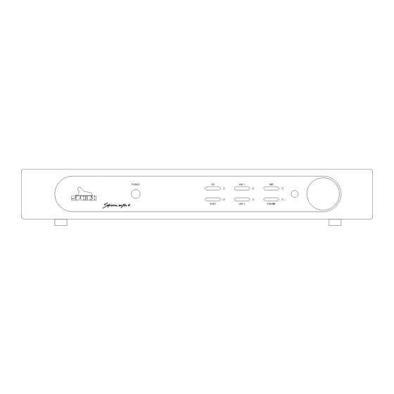
Page 4: The Amp At A Glance
SPHINX Myth 5 Service Manual 3. THE AMP AT A GLANCE Front panel 1. PHONES: To connect dynamic stereo 7. STANDBY: To switch the component on and off. headphones. When the component is 'off' (standby) this is indicated by the red LED. -
Page 5: Rear Panel
SPHINX Myth 5 Service Manual Rear panel 10 11 12 13 14 15 10. LINE 2: To connect the cinch signal cable from 18. Manufacturer’s label: This shows important the signal source for LINE 2. data for the component, such as serial number and mains power voltage. -
Page 6: Operation
SPHINX Myth 5 Service Manual 4. OPERATION Adjusting the volume Once you have finished connecting all components, Using the large VOLUME control (9) you can adjust you can switch on the Myth 5. the sound level from the loudspeakers. This volume control is motor-controlled. If you adjust Connect the mains cable to a mains outlet. -
Page 7: Sphinx Remote Control
SPHINX Myth 5 Service Manual 5. SPHINX REMOTE CONTROL This single Sphinx Remote Control allows you to control all functions: not only of the Myth 5, but of all other Sphinx equipment. Only the following buttons and indications on the... -
Page 8: Operation
SPHINX Myth 5 Service Manual Operation Encountering problems... The Sphinx Remote is used with several different models and can therefore transmit different control codes, depending on which model has been Remote Control does not work selected with the select buttons (1). -
Page 9: Technical Specifications
This unit conforms to the EMC interference regulations issued by the EU and to the CE standards. This unit complies with safety regulation VDE 0860 and therefore with international safety regulation IEC 65. Technical specifications may be changed by SPHINX without prior notice if technical developments make this necessary. -
Page 10: Adjustment Procedures
SPHINX Myth 5 Service Manual ADJUSTMENT PROCEDURES Offset The Myth 5 is an integrated amplifier, meaning the The Offset adjustment procedure minimises the DC pre-amp and power amp sections are combined into offset value of the amplifier output. This DC offset is one cabinet. -
Page 11: Problems And Solutions
At the moment of writing the Myth 5 has no known Please also send (by fax or e-mail) the specific specific problems. information to the Sphinx International Service If in the future you encounter any problem(s) you Department (see page 3): this info can then be may enter the info in this table. -
Page 12: Diagrams And Parts Lists
SPHINX Myth 5 Service Manual 9. DIAGRAMS AND PARTS LISTS The next pages contain the front and rear panel lay- out and a complete set of schematic drawings including the associated parts lists (if applicable). -
Page 13: Measurement Set-Up
SPHINX Myth 5 Service Manual Measurement Set-up Oscillator Frequency Amplitude time/div out1 out2 inp1 inp1 inp2 THD out inp2 out1 out2 Scoop Left Right inp1 inp2 SWITCH-BOX MYTH 3... -
Page 14: General Overview Myth 5
SPHINX Myth 5 Service Manual General Overview Myth 5 Myth 5 Myth 5 amplifier left channel Myth 5 amplifier right channel M5-IO.SCH M5-AMPL.SCH M5-AMPR.SCH SIG_R SIG_R SIG-R SIG-R SIG_L SIG_L SIG_L SIG_L Myth 5 powersupply Myth 5 keyboard Myth 5 control M5-PS.SCH... -
Page 15: Schematic Diagram Power Supply
SPHINX Myth 5 Service Manual Schematic Diagram Power Supply NTC1 ACP1 ACINP1 ACS1 2.5E/8A SW1B 220N 220N SW1A ACP2 115_230 ACS2 115_230 EARTH SB356 ACS3 220N 220N ACP3 ACS4 ACP4 ACINP2 BD679 +24V +24VOUT 56R/2W 1N4148 ZF24V GNDOUT... -
Page 16: Schematic Diagram Amplifier Left
SPHINX Myth 5 Service Manual Schematic Diagram Amplifier Left 220U/63V R22L 10U/100V 100N 100N V+_BEV R16L 120K 820R 820R 56R0 C11L C12L C17L C16L R15L R17L AGND AGND C1775 C1775 A970 A970 Q10L C2705 R25L Hoofdtelefoon Q12L AGND C4382 REL6LC... -
Page 17: Schematic Diagram Amplifier Right
SPHINX Myth 5 Service Manual Schematic Diagram Amplifier Right 220U/63V 10U/100V R22R 100N 100N V+_BEV R16R 120K 820R 820R 56R0 C11R C12R C17R C16R R15R R17R AGND AGND C1775 C1775 A970 A970 Q10R C2705 R25R Hoofdtelefoon Q12R AGND C4382 REL6RC... -
Page 18: Schematic Diagram Input/Output
SPHINX Myth 5 Service Manual Schematic Diagram Input/Output LINE2 LINE1 TUNER TAPE OUT TAPE IN L2/L1A L2/L1B TUNER/CDA TUER/CDB TAPEA TAPEB AGND REL1 REL2 REL3 REL4 REL5 REL16 REL16 REL16 REL16 R41L R41R REL16 475R 475R +24V R42L R42R 475R... -
Page 19: Schematic Diagram Keyboard
SPHINX Myth 5 Service Manual Schematic Diagram Keyboard S-L2 S-CD S-TUNER S-L1 S-MUTE S-TAPE S-GND L+24V +24V TAPE-M L-TAPE LINE2 L-L2 L-CD TUNER L-TUNER LINE1 L-L1 MUTE L-MUTE... -
Page 20: Schematic Diagram Control
SPHINX Myth 5 Service Manual Schematic Diagram Control PROTECT 100N BC807 BC807 +40V BC817 330U/6V KAST 100N 1N4148 1N4148 +24V 100N 100N 100N 100N 100N 100N DGND FL-ERROR DGND DGND 100N BCV46 +24VS DGND 100N 1N4148 +24V 7805 BC817 +24V... -
Page 21: Parts List
SPHINX Myth 5 Service Manual Parts List Designator Part Type Description +24VOUT 1PIN Connector ACINP1 1PIN Connector ACINP2 1PIN Connector ACP1 1PIN Connector ACP2 1PIN Connector ACP3 1PIN Connector ACP4 1PIN Connector ACS1 1PIN Connector ACS2 1PIN Connector ACS3 1PIN... - Page 22 SPHINX Myth 5 Service Manual Designator Part Type Description 100N MKT capacitor 2200U/50V Electrolitic capacitor C19L 100N MKT capacitor C19R 100N MKT capacitor C1AL 120P MKT capacitor C1AR 120P MKT capacitor C1BL 120P MKT capacitor C1BR 120P MKT capacitor 100N...
- Page 23 SPHINX Myth 5 Service Manual Designator Part Type Description 100N MKT capacitor 100N MKT capacitor 2200U/50V Electrolitic capacitor 100N MKT capacitor 100N MKT capacitor 100N MKT capacitor 2200U/50V Electrolitic capacitor MKT capacitor MKT capacitor Electrolitic capacitor 2200U/50V Electrolitic capacitor 330N...
- Page 24 SPHINX Myth 5 Service Manual Designator Part Type Description L-L1 Connector L-L2 Connector L-MUTE Connector L-TAPE Connector L-TUNER Connector Connector Connector OUT- Connector OUT- Connector OUT+ Connector OUT+ Connector OVER_CL Connector OVER_CR Connector Connector Connector Connector Connector PTC1 Connector PTC1...
- Page 25 SPHINX Myth 5 Service Manual Designator Part Type Description Zener diode SB356 Diode Zener diode 1N4148 Diode 1N4007 Diode 1N4007 Diode 1N4007 Diode 1N4007 Diode 1N4148 Diode 1N4148 Diode EARTH 1PIN Connector GEEL Connector GNDOUT 1PIN Connector GROEN LEFT Connector...
- Page 26 SPHINX Myth 5 Service Manual Designator Part Type Description Q10L C2705 Transisor Q10R C2705 Transisor BC807 Transisor Q11L A1145 Transisor Q11L A1145 Transisor BC817 Transisor Q12L C4382 Transisor Q12R C4382 Transisor BC807 Transisor Q13L A1668 Transisor Q13R A1668 Transisor BCV46...
- Page 27 SPHINX Myth 5 Service Manual Designator Part Type Description Resistor 475R Resistor Resistor 56R/2W Resistor R10L Resistor R10R Resistor 390R Resistor Resistor R11L 1K00 Resistor R11R 1K00 Resistor 390R Resistor Resistor R12L 475R Resistor R12R 475R Resistor Resistor R13L Resistor...
- Page 28 SPHINX Myth 5 Service Manual Designator Part Type Description R24R Resistor R25L Resistor R25R Resistor R26L Resistor R26R Resistor R27L 56R/2W Resistor R27R 56R/2W Resistor R28L 100R Resistor R28R 100R Resistor R29L 100R Resistor R29R 100R Resistor 22K0 Resistor 22K0...
- Page 29 SPHINX Myth 5 Service Manual Designator Part Type Description Resistor Resistor Resistor Resistor Resistor Resistor 120K Resistor 120K Resistor Resistor 820R Resistor 820R Resistor Resistor 820R Resistor 820R Resistor Resistor Resistor REL1 REL16 Relay REL2 REL16 Relay REL3 REL16 Relay...
Need help?
Do you have a question about the Myth5 and is the answer not in the manual?
Questions and answers