
Related Manuals for SPHINX Project Eight


Summary of Contents for SPHINX Project Eight
- Page 1 SPHINX Project Eight Service Manual SERVICE MANUAL PROJECT EIGHT REFERENCE PRE-AMP...
-
Page 2: Table Of Contents
Figure 1: Front panel ..........................12 Figure 2: Rear panel ..........................12 Index of diagrams and drawings ........................ 13 Figure 3: Connection Diagram for testing the Project Eight............... 14 Figure 4: Display Board Schematic Layout....................15 Figure 5: Construction Drawing for top cover plate..................16 Figure 6: Schematic Operational Diagram Project Eight ................ -
Page 3: Unpacking
We are very proud of the tradition connected with looking product. the SPHINX name, especially concerning audio We recommend owners to ship the Project Eight in quality perfection. its original carton. This service manual will help you to optimally... -
Page 4: Technical Specifications
This unit conforms to the EMC interference regulations issued by the EU and to the CE standards. This unit complies with safety regulation VDE 0860 and therefore with international safety regulation IEC 65. Technical specifications may be changed by SPHINX without prior notice if technical developments make this necessary. -
Page 5: General Checklist
Serial number and software version The serial number and software version should match those mentioned in the documentation as supplied with every Project Eight. Switch off the mains power. Press the Standby button. Switch the mains on again while holding the Standby button depressed. -
Page 6: Sphinx Remote Control
Service Manual 6. SPHINX REMOTE CONTROL This single Sphinx Remote Control lets you control all functions: not only of the Project Eight, but of all other Sphinx equipment. Moreover: you may also use it to control other types of equipment (e.g. TV and VCR) thanks to the... -
Page 7: Operation
If you depress one of the other component select buttons (than TV or VCR) you will erase 1. Place both the Sphinx Remote Control and the the commands for a Sphinx audio component! other remote (TV or VCR) flat on a table, facing You should only do this if you do not have that each other with a spacing of no more than 2 cm. -
Page 8: The Led During Normal Mode
The memory holds a maximum of 120 commands. Component reacts differently than expected or Warning: If you don't know exactly what you are not at all doing, please consult your Sphinx dealer! Wrong component selected Select the correct one Wrong command programmed... -
Page 9: Measurements
Audio signal distortion measurement 7. MEASUREMENTS Before adjusting the Project Eight please first To properly service the Project Eight you need measure the total harmonic distortion at the audio some specific measurement equipment and use a output. The measured value is an indication of the specific set-up. -
Page 10: Output Dc-Offset Adjustment
Remove the top cover of the Project Eight and Turn the volume of the project eight to ‘ off’ . The replace it with the special cover plate (with offset currently visible on the mV-meter is the adjustment holes, see figure 5 at page 16). -
Page 11: Problems And Solutions
Service Manual 9. PROBLEMS AND SOLUTIONS Please also send (by fax or e-mail) the specific At the moment of writing the Project Eight has one information to the Sphinx International Service known specific problem. Department (see page 3): this info can then be If in the future you encounter any problem(s) you added to the general database to aid others. -
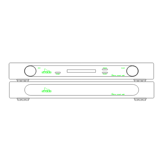
Page 12: Diagrams And Parts Lists
SPHINX Project Eight Service Manual 10. DIAGRAMS AND PARTS LISTS The next pages contain the front and rear panel lay- out and a complete set of schematic drawings including the associated parts lists (if applicable). Figure 1: Front panel Figure 2: Rear panel... -
Page 13: Index Of Diagrams And Drawings
SPHINX Project Eight Service Manual Index of diagrams and drawings Page Description Connection Diagram for testing the Project Eight Display Board Schematic Layout Construction Drawing for top cover plate Schematic Operational Diagram Project Eight Schematic Overview of all relevant potentiometers... -
Page 14: Figure 3: Connection Diagram For Testing The Project Eight
SPHINX Project Eight Service Manual Figure 3: Connection Diagram for testing the Project Eight Oscillator Frequency Amplitude time/div out1 out2 inp1 inp1 inp2 THD out inp2 out1 out2 Scoop Left Left Amplfier (30x) Pre-amplfier (3x) Right Right inp1 inp2 SWITCH-BOX... -
Page 15: Figure 4: Display Board Schematic Layout
SPHINX Project Eight Service Manual Figure 4: Display Board Schematic Layout TO MAINBOARD UCN'S TO VFD-DISPLAY 18PIN 20PIN 470U/16V 68K1 3U3/63V 1N4148 P76/RD P75/WR 93C46 H8/325 MAX690 220n 27K4 10K0 220n 220n ENCOD NORMAL JUMPER SETTINGS JUMPER CLOSED OPEN 220n... -
Page 16: Figure 5: Construction Drawing For Top Cover Plate
SPHINX Project Eight Service Manual Figure 5: Construction Drawing for top cover plate All sizes in millimeters For holes use drill size of approx. Ø 6 mm Holes use same spacing as the ones shown below Top View... -
Page 17: Figure 6: Schematic Operational Diagram Project Eight
SPHINX Project Eight Service Manual Figure 6: Schematic Operational Diagram Project Eight project eight main board disamp disamp module 5 module 1 left disamp disamp module 6 module 2 top view disamp disamp module 7 module 3 right disamp disamp... -
Page 18: Figure 7: Schematic Overview Of All Relevant Potentiometers
SPHINX Project Eight Service Manual Figure 7: Schematic Overview of all relevant potentiometers DISAMP DISAMP RIGHT DISAMP DISAMP DISAMP DISAMP LEFT DISAMP DISAMP... -
Page 19: Figure 8: Disamp-96
SPHINX Project Eight Service Manual Figure 8: Disamp-96 4PIN 4PIN 4PIN 24R9 A1306 C3298 100R 10R0 10R0 100R 51R0 51R0 ± 7.5mA A1145 C2705 243R 243R ± 7.5 mA A1145 C2705 600R 18R0 18R0 600R 1N4148 1N4148 AGND AGND 4K75... -
Page 20: Figure 9: Functional Schematic
-RV-OUT -RV-OUT -RV-OUT -RV-IN -RV-IN -RV-IN -RV-IN -R-IN -R-IN SP14 +R-OUT +R-OUT +RV-OUT +RV-OUT +RV-OUT +RV-OUT +RV-IN +RV-IN +RV-IN +RV-IN +R-IN +R-IN R-38V R-38V R-24V R-24V R-24V R-24V R-24V R-24V CINCH CINCH P08RPR.SCH P08ROA.SCH P08RVC.SCH P08RIA.SCH Project Eight Functional Schematic... -
Page 21: Figure 10: Left Power Supply
SPHINX Project Eight Service Manual Figure 10: Left Power Supply AGND L+24V L-24V 63V/2200U 63V/2200U 1R00 1R00 22N/PP 22N/PP ± 6.9V 50V/330U 50V/330U 10K0 10K0 LM329DZ LM329DZ 1K00 1K00 ± 24V 150..160 mA 150..160 mA 22N/PP 22N/PP 6.9V 50V/330U 50V/330U 6.9V... -
Page 22: Figure 11: Right Power Supply
SPHINX Project Eight Service Manual Figure 11: Right Power Supply AGND AGND R+24V R-24V C63V/2200U 63V/2200U 1R00 1R00 22N/PP 22N/PP 50V/330U 50V/330U 10K0 10K0 LM329DZ LM329DZ 150..160 mA 150..160 mA 1K00 1K00 22N/PP 22N/PP 50V/330U C50V/330U 8K25 8K25 3K32 3K32... -
Page 23: Figure 12: Input/Output
SPHINX Project Eight Service Manual Figure 12: Input/Output CN24 RL58 +R-IN -R-IN RL57 XLR FEMALE AGND CN23 RL56 +L-IN -L-IN XLR FEMALE CN22 RL55 RL54 XLR FEMALE AGND CN21 RL53 XLR FEMALE RL52 CN20 RL47 CINCH CN19 RL42 CINCH CN18... -
Page 24: Figure 13: Left Volume Control
SPHINX Project Eight Service Manual Figure 13: Left Volume Control -LV-IN +LV-IN R145 2K00 R142 R144 2K00 2K00 AGND R143 2K00 RL49 R135 R139 634K 634K C103 100NMKT RL44 R131 0R00 AGND 100NMKT R127 0R00 RL39 R123 10R0 AGND 100NMKT... -
Page 25: Figure 14: Right Volume Control
SPHINX Project Eight Service Manual Figure 14: Right Volume Control -RV-IN +RV-IN R149 2K00 R146 R148 2K00 2K00 AGND R147 2K00 RL51 R137 R141 634K 634K C105 100NMKT RL46 R133 0R00 C101 AGND 100NMKT R129 0R00 RL41 R125 10R0 AGND... -
Page 26: Figure 15: Left Output Amp
SPHINX Project Eight Service Manual Figure 15: Left Output Amp 1R00 L+24V + C45 37..40mA C63V/2200U 47N/PP AGND -L-OUT -LV-OUT 2x0.3 zilver 100K 220p AGND AGND DISAMPMODULE AGND + C48 C63V/2200U 47N/PP 1R00 L-24V 37..40mA 10K0 .1% 10K0 .1% 10K0 .1%... -
Page 27: Figure 16: Right Output Amp
SPHINX Project Eight Service Manual Figure 16: Right Output Amp 1R00 R+24V + C53 37..40mA C63V/2200U 47N/PP AGND -R-OUT -RV-OUT 2x0.3 zilver 100K 220p AGND AGND DISAMPMODULE AGND + C56 C63V/2200U 47N/PP R-24V 1R00 37..40mA 10K0 .1% 10K0 .1% 10K0 .1%... -
Page 28: Figure 17: Left Input Amp
SPHINX Project Eight Service Manual Figure 17: Left Input Amp R150 1R00 L+24V + C106 37..40mA C107 C63V/2200U 47N/PP AGND -LV-IN R170 +L-IN 1K00 C122 R166 220p 50K0 AGND AGND DISAMPMODULE AGND + C109 C108 C63V/2200U R151 47N/PP 1R00 L-24V 37..40mA... -
Page 29: Figure 18: Right Input Amp
SPHINX Project Eight Service Manual Figure 18: Right Input Amp R154 1R00 R+24V + C114 37..40mA C115 C63V/2200U 47N/PP AGND -RV-IN R172 +R-IN 1K00 C124 R168 220p 50K0 AGND AGND DISAMPMODULE AGND + C117 C116 C63V/2200U R155 47N/PP 1R00 R-24V 37..40mA... -
Page 30: Figure 19: Power Supply Unit
SPHINX Project Eight Service Manual Figure 19: Power Supply Unit R-CORE 50VA + C5 + C6 120V 10K0 BRIDGE6 C50V/6800U C50V/6800U 120V + C11 + C12 10K0 BRIDGE6 5PIN C50V/6800U C50V/6800U R-CORE 50VA + C17 + C18 120V 10K0 DGND... -
Page 31: Figure 20: Pcb Drawings
SPHINX Project Eight Service Manual Figure 20: PCB drawings Because there is a significant image-quality loss during the conversion of the drawings, The PCB-drawings are located in separate files. These files are in PDF-format (Adobé Acrobat 3.0 Reader) Project 8 mainboard (A3 format) “... -
Page 32: Parts List
SPHINX Project Eight Service Manual Parts List Designator Part Type Description BRIDGE6 Bridge rectifier BRIDGE6 Bridge rectifier BRIDGE6 Bridge rectifier BRIDGE6 Bridge rectifier BRIDGE6 Bridge rectifier BRIDGE6 Bridge rectifier 100NMKT Capacitor 330N/PP Capacitor Capacitor Capacitor 100NMKT Capacitor C25V/47U Capacitor C63V/1000U... - Page 33 SPHINX Project Eight Service Manual Designator Part Type Description C63V/1000U Capacitor 100NMKT Capacitor C50V/330U Capacitor 100NMKT Capacitor 330N/PP Capacitor 100NMKT Capacitor 330N/PP Capacitor 330N/PP Capacitor C50V/6800U Capacitor 330N/PP Capacitor C50V/6800U Capacitor 22N/PP Capacitor C63V/2200U Capacitor 100NMKT Capacitor C50V/330U Capacitor C50V/330U...
- Page 34 SPHINX Project Eight Service Manual Designator Part Type Description 220p Capacitor 220p Capacitor 220p Capacitor 220p Capacitor 100NMKT Capacitor 100NMKT Capacitor 100NMKT Capacitor 100NMKT Capacitor 100NMKT Capacitor 100NMKT Capacitor 330N/PP Capacitor 3U3/63V Capacitor C25V/47U Capacitor 100NMKT Capacitor 100NMKT Capacitor 100NMKT...
- Page 35 SPHINX Project Eight Service Manual Designator Part Type Description 4PIN Connector 5PIN Connector XLR MALE Connector CN20 CINCH Connector CN21 XLR FEMALE Connector CN22 XLR FEMALE Connector CN23 XLR FEMALE Connector CN24 XLR FEMALE Connector 4PIN Connector XLR MALE Connector...
- Page 36 SPHINX Project Eight Service Manual Designator Part Type Description 27K4 Resistor 4k75 Resistor Resistor 1R00 Resistor 4K75 Resistor R100 20K0 Resistor R101 80R6 Resistor R102 10K0 Resistor R103 40R2 Resistor R104 10K0 Resistor R105 40R2 Resistor R106 10K0 Resistor R107...
- Page 37 SPHINX Project Eight Service Manual Designator Part Type Description Resistor R150 1R00 Resistor R151 1R00 Resistor R152 1R00 Resistor R153 1R00 Resistor R154 1R00 Resistor R155 1R00 Resistor R156 1R00 Resistor R157 1R00 Resistor R158 10K0 .1% Resistor R159 10K0 .1%...
- Page 38 SPHINX Project Eight Service Manual Designator Part Type Description 10K0 Resistor 332R Resistor Resistor 243R Resistor 332R Resistor Resistor 4k75 Resistor 51R0 Resistor 5R62 Resistor Resistor 200R Resistor 2K00 Resistor 100R Resistor 2K00 Resistor 100K Resistor Resistor 200R Resistor Resistor...
- Page 39 SPHINX Project Eight Service Manual Designator Part Type Description 100K Resistor 10K0 Resistor 22K1 Resistor 51R0 Resistor 100K Resistor 100K Resistor 100K Resistor 100K Resistor 2x0.3 silver Resistor 2x0.3 zilver Resistor 2x0.3 zilver Resistor 2x0.3 zilver Resistor 84K5 Resistor 324R...
- Page 40 SPHINX Project Eight Service Manual Designator Part Type Description RL33 REL16 Relay 24V RL34 REL16 Relay 24V RL35 REL16 Relay 24V RL36 REL16 Relay 24V RL37 REL16 Relay 24V RL38 REL16 Relay 24V RL39 REL16 Relay 24V REL16 Relay 24V...
- Page 41 SPHINX Project Eight Service Manual Designator Part Type Description C2240 Transistor C3298 Transistor A1145 Transistor A1306 Transistor C2705 Transistor C3298 Transistor A1145 Transistor A970 Transistor A1306 Transistor C2705 Transistor C2240 Transistor C3298 Transistor A970 Transistor C2240 Transistor A1306 Transistor K389...
- Page 42 SPHINX Project Eight Service Manual Designator Part Type Description LM329DZ ZENER Diode LM329DZ ZENER Diode LM329DZ ZENER Diode ©1998 Audioscript BV Version: May 13, 1998...
Need help?
Do you have a question about the Project Eight and is the answer not in the manual?
Questions and answers