Keysight U2722A User Manual
Usb modular source measure units
Hide thumbs
Also See for U2722A:
- Service manual (50 pages) ,
- Service manual (45 pages) ,
- Programmer's reference manual (141 pages)
Table of Contents
Advertisement
Quick Links
Download this manual
See also:
Service Manual
Advertisement
Table of Contents

Related Manuals for Keysight U2722A


Summary of Contents for Keysight U2722A
- Page 1 Keysight U2722A/U2723A USB Modular Source Measure Units User’s Guide...
- Page 4 Printed in Malaysia forth therein, does not require or CONTAINED HEREIN. SHOULD Published by: permit, among other things, that KEYSIGHT AND THE USER HAVE A Keysight: (1) Furnish technical SEPARATE WRITTEN AGREEMENT Keysight Technologies information related to commercial WITH WARRANTY TERMS COVERING...
-
Page 5: Safety Symbols
Caution, risk of danger (refer to this Earth (ground) terminal manual for specific Warning or Caution information) Protective conductor terminal Caution, hot surface Frame or chassis terminal Out position of a bi-stable push control Equipotentiality In position of a bi-stable push control Keysight U2722A/U2723A User’s Guide... -
Page 6: General Safety Information
– Always use dry cloth to clean the device. Do not use ethyl alcohol or any other volatile liquid to clean the device. – Do not permit any blockage of the ventilation holes of the device. Keysight U2722A/U2723A User’s Guide... -
Page 7: Environmental Conditions
20% to 85% RH non-condensing Storage temperature –20 °C to 70 °C Storage humidity 5% to 90% RH non-condensing The U2722A/U2723A USB Modular Source Measure Units complies with the NOTE following safety and EMC requirements: – IEC 61326-1:2005/EN61326-1:2006 – Canada: ICES-001:2004 –... -
Page 8: Regulatory Markings
Cet appareil ISM est conforme a la this electrical or electronic product in norme NMB-001 du Canada. domestic household waste. The CSA mark is a registered trademark of the Canadian Standards Association. Keysight U2722A/U2723A User’s Guide... -
Page 9: Waste Electrical And Electronic Equipment (Weee) Directive 2002/96/Ec
To return this unwanted instrument, contact your nearest Keysight Service Center, or visit http://about.keysight.com/en/companyinfo/environment/takeback.shtml for more information. Sales and Technical Support To contact Keysight for sales and technical support, refer to the support links on the following Keysight websites: – www.keysight.com/find/U2722A (product-specific information and support, software and documentation updates) –... - Page 10 THIS PAGE HAS BEEN INTENTIONALLY LEFT BLANK. Keysight U2722A/U2723A User’s Guide...
-
Page 11: Table Of Contents
Sourcing and Measurement ........35 Keysight U2722A/U2723A User’s Guide... - Page 12 Appendix B: Time-out Settings ....... 68 Index Keysight U2722A/U2723A User’s Guide...
-
Page 13: Keysight U2722A/U2723A User's Guide
Figure 2-1 U2722A/U2723A fundamental concepts ...35 Figure 2-2 Panel view of the Keysight Measurement Manager . .36 Figure 2-3 Turning on the U2722A/U2723A ....37... - Page 14 THIS PAGE HAS BEEN INTENTIONALLY LEFT BLANK. Keysight U2722A/U2723A User’s Guide...
- Page 15 ....66 Table 4-2 Time-out settings ......68 Keysight U2722A/U2723A User’s Guide...
- Page 16 THIS PAGE HAS BEEN INTENTIONALLY LEFT BLANK. Keysight U2722A/U2723A User’s Guide...
- Page 17 Instrument Configuration Cable Installation Chassis Installation This chapter provides an overview of the U2722A/U2723A USB Modular Source Measure Units, which includes the product outlook, product dimensions, and product layout. This chapter also contains instructions on how to install and configure the U2722A/U2723A.
-
Page 18: Getting Started
Introduction The Keysight U2722A/U2723A USB Modular Source Measure Units (SMU) can operate as a standalone or modular unit when used in a chassis. The U2722A/ U2723A has three outputs. The voltage range is –20 V to 20 V, whereas the maximum current output per channel is 120 mA. -
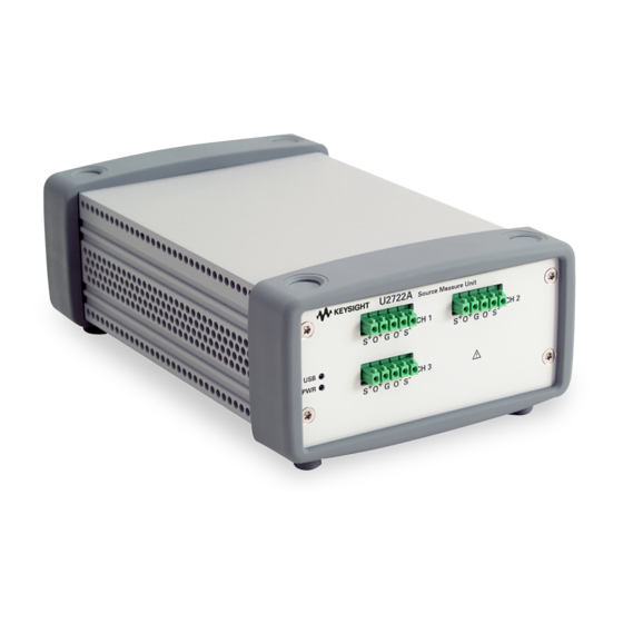
Page 19: Product At A Glance
Getting Started Product at a Glance Product outlook Top view Bumpers Keysight U2722A/U2723A User’s Guide... - Page 20 Getting Started U2722A USB Modular Source Measure Unit front view Output connector (Channel 1) USB indicator Power indicator U2723A USB Modular Source Measure Unit front view Output connector (Channel 1) USB indicator Power indicator Keysight U2722A/U2723A User’s Guide...
- Page 21 Getting Started U2722A USB Modular Source Measure Unit rear view USB inlet 55-pin backplane connector Fastening hole for USB cable with locking mechanism Power inlet U2723A USB Modular Source Measure Unit rear view USB inlet Rear ventilation fan 55-pin backplane connector...
-
Page 22: Product Dimensions
Getting Started Product Dimensions Dimensions without bumpers Top view 105.00 mm 175.00 mm Front view 50.00 mm Keysight U2722A/U2723A User’s Guide... -
Page 23: Dimensions With Bumpers
Getting Started Dimensions with bumpers Top view 120.00 mm 183.00 mm Rear view 66.00 mm Keysight U2722A/U2723A User’s Guide... -
Page 24: Standard Shipped Items
Getting Started Standard Shipped Items Verify that you have received the following items with your unit. If anything is missing or damaged, please contact the nearest Keysight Sales Office. – 12 V, 3 A AC/DC adapter – Power cord – Plug-in connectors and cable casing –... -
Page 25: Inspection And Maintenance
Keep the original packaging in case the U2722A/U2723A has to be returned to Keysight in the future. If you return the U2722A/U2723A for service, attach a tag identifying the owner and model number. Also include a brief description of the problem. -
Page 26: General Maintenance
2 Remove your module from the bumper casing. 3 Shake out any dirt that may have accumulated on the module. 4 Wipe your module with a dry cloth and install the bumper back in place. Keysight U2722A/U2723A User’s Guide... -
Page 27: Installation And Configuration
Getting Started Installation and Configuration Follow the step-by-step instructions shown in the Keysight USB Modular Products and Systems Quick Start Guide to get started with the preparations and installations of your U2722A/U2723A. You need to install the IVI-COM driver if you are going to use the NOTE ®... -
Page 28: Instrument Configuration
Getting Started Instrument Configuration Connector configuration The U2722A/U2723A is equipped with output connectors as shown in Figure 1-1. SENSE OUTPUT GUARD OUTPUT SENSE Figure 1-1 Output connectors The SENSE outputs must not be left unconnected. It must be connected locally NOTE or remotely. -
Page 29: Figure 1-2 55-Pin Backplane Connector Pin Configuration
Getting Started 55-pin backplane connector pin configuration The 55-pin backplane connector is used when the U2722A/U2723A module is inserted into the U2781A USB modular instrument chassis. For more details, refer to the Keysight U2781A USB Modular Instrument Chassis User's Guide. -
Page 30: Cable Installation
Cable casing Push the cables through the cable casing. Cables Connector Then, insert the cables into the cable connector and fasten it. Push the cable casing towards the output connector until it firmly envelops the connector. Keysight U2722A/U2723A User’s Guide... - Page 31 Getting Started The connector should be enveloped by the cable casing as shown. This figure provides the full view of the connected cables to the instrument’s connector. Keysight U2722A/U2723A User’s Guide...
-
Page 32: Chassis Installation
Getting Started Chassis Installation The L-Mount kit is to be installed to your U2722A/U2723A module. The following instructions describe the simple procedure of installing the L-Mount kit and your module in the chassis. 1 Unpack the L-Mount kit from the packaging. -
Page 33: Operation And Features
Memory List This chapter describes the source voltage and source current operation mode of the U2722A/U2723A USB Modular Source Measure Units. It also explains the importance of remote sense and guarding when performing low current measurements. There is a section that provides information on extending the... -
Page 34: Power Up
U2722A/U2723A. Refer to the Keysight USB Modular Products and Systems Quick Start Guide for the installation procedure. – On the front panel of the U2722A/U2723A, there are two LED indicators. Refer “Product outlook” on page 19. -
Page 35: Sourcing And Measurement
Operation and Features Sourcing and Measurement The fundamental concepts of the U2722A/U2723A are as shown in Figure 2-1. When programmed to source voltage mode, the ammeter (I ) is connected in meter series with the voltage source (V ) and the output. If the U2722A/U2723A is... -
Page 36: Source Voltage Operation
OUTPUT– terminals of an output channel. 2 Turn on the U2722A/U2723A. The U2722A/U2723A will go into a power-on or reset state; the output is disabled. Ensure that the USB interface has already been connected between the U2722A/U2723A and PC. Run the Keysight Measurement Manager software to control the U2722A/U2723A remotely. -
Page 37: Figure 2-3 Turning On The U2722A/U2723A
Figure 2-4 Turning off the U2722A/U2723A In source voltage mode, the U2722A/U2723A will maintain a constant output voltage based on the set value. The output current will vary according to the load. The input protection current settings represents the limit value. -
Page 38: Figure 2-5 Source Voltage Positive Operating Boundaries
Figure 2-6 shows the operation with different resistive loads, which are 1 kΩ and 100 Ω respectively. In these examples, the U2722A/U2723A is having a source voltage of 15 V and an input protection current of 50 mA. Keysight U2722A/U2723A User’s Guide... -
Page 39: Figure 2-6 Source Voltage Operation
Source voltage operation Figure 2-6 (A), the U2722A/U2723A is having a source voltage of 15 V to a 1 kΩ load and it is measuring 15 mA. As long as the DUT load line intersects the source voltage line, it will be in source voltage mode and the voltage will maintain at 15 V. -
Page 40: Source Current Operation
2 Turn on the U2722A/U2723A. The U2722A/U2723A will go into a power-on or reset state; the output is disabled. Ensure that the USB interface has already been connected between the U2722A/U2723A and PC. Load the Keysight Measurement Manager software to control the U2722A/U2723A remotely. -
Page 41: Figure 2-7 Source Current Positive Operating Boundaries
Figure 2-8 shows the operation with different resistive loads, which are 1 kΩ and 100 Ω respectively. In these examples, the U2722A/U2723A is having a source current of 20 mA and an input protection voltage of 15 V. Keysight U2722A/U2723A User’s Guide... -
Page 42: Figure 2-8 Source Current Operation
1 kΩ, the DUT load line intersects the input protection voltage line. This forces the U2722A/U2723A to go into source voltage mode. Since the voltage setting is clamped at 15 V and the U2722A/U2723A cannot operate out of the boundary, the current then changes to 15 mA instead. -
Page 43: Channel Control Using Scpi Commands
Sets current range of channel 1 to 8 mA. → SOUR:CURR:LIM 8mA,(@1) Sets channel 1 to output 5 V. → SOUR:VOLT 5,(@1) → OUTP ON,(@1) Turns on output for channel 1. Queries the voltage for channel 1. → MEAS:VOLT? (@1) ← 4.99 Keysight U2722A/U2723A User’s Guide... - Page 44 → SOUR:VOLT:LIM 10V, (@1) → SOUR:CURR 5mA, (@1) Sets channel 1 to output 5 mA. Turns on output for channel 1. → OUTP ON, (@1) Queries the current for channel 1. → MEAS:CURR? (@1) ← 5.0E-03 Keysight U2722A/U2723A User’s Guide...
-
Page 45: Remote Sense And Guard
DUT. When the U2722A/U2723A is in source voltage mode, remote sensing enables the voltage to be sensed at the load and it will result in better regulation. If the... -
Page 46: Figure 2-10 Remote Sense Connection
SENSE+ lines and the GUARD line. Therefore, there will not be any leakage current flowing from either the OUTPUT+ and SENSE+ lines. The leakage current from the GUARD does not affect the measurement results because it does not flow into the I meter. Keysight U2722A/U2723A User’s Guide... -
Page 47: Figure 2-11 Guarded Connection
GUARD terminal potential is equal to the output. WARNING Never connect the GUARD terminal to any other output, including circuit CAUTION common, chassis ground, or the GUARD terminal of any other unit. Doing so may result in damage to the unit. Keysight U2722A/U2723A User’s Guide... -
Page 48: Making Measurements
Operation and Features Making measurements The U2722A/U2723A has an excellent output voltage and current measurement capability. All the measurements are performed by digitizing the instantaneous output voltage or current for a defined number of samples and sample interval, storing the results in a buffer, and then calculating the measured result. The programmable parameters include the number of samples and time interval between each sample. -
Page 49: Figure 2-12 Commands That Control Measurement Time
5.115 s. Hence, it is recommended that the time-out settings for communicating with the U2722A/U2723A is set to more than 5.115 s, else time-out error would likely occur. Controlling measurement samples You can vary the number of data points in a measurement sample and the time between samples. - Page 50 MEASure:ARRay:CURRent[:DC]? (@1|2|3) commands are governed by the number of data points and time interval settings. You are required to configure the time-out settings via the Keysight IO Libraries NOTE when different values of the sweep points and time interval are set. For more...
-
Page 51: System-Related Operation
Disconnect all connections from the output terminals. Ensure that the output terminals are not connected to any loads. Turn on the U2722A/U2723A. On the application panel, select Tools > Sel f-Test. If the self-test fails, an error is recorded in the instrument error queue. -
Page 52: Error Conditions
Operation and Features Error conditions A record of up to 20 errors can be stored in the U2722A/U2723A's error queue. Refer to the programming guide for more information on the error messages. Keysight Measurement Manager operation A message box will appear once an error occurs while operating the U2722A/ U2723A using the Keysight Measurement Manager. -
Page 53: Extending The Output Power
Operation and Features Extending the Output Power The U2722A/U2723A is equipped with three dedicated channels of up to 20 V and 120 mA per channel. Series connections To increase the output voltage, tie two or more of the outputs in series as shown Figure 2-13. -
Page 54: Parallel Connections
SENSE OUTPUT GUARD OUTPUT SENSE SENSE OUTPUT GUARD OUTPUT SENSE SENSE OUTPUT GUARD OUTPUT SENSE Negative (–) terminal of the device-under-test Positive (+) terminal of the device-under-test Figure 2-14 U2722A/U2723A outputs connected in parallel – Ensure that the voltage (when source current) or the current (when source NOTE voltage) is not clamped. -
Page 55: Memory List
You may also set the number of times this range of commands is to be executed. The default loop set is 1 and the maximum loop number is 1000. Keysight U2722A/U2723A User’s Guide... -
Page 56: Memory List Commands Storing And Restoring
Set the global delay value [SOURce:]MEMory:SOURce:DELay LocalDelay Set the local delay value [SOURce:]MEMory:OUTPut Output Enable (ON) or disable (OFF) the instrument output For more information, refer to the Keysight U2722A/U2723A USB Modular Source Measure Units Programmer’s Reference. Keysight U2722A/U2723A User’s Guide... -
Page 57: Memory List Delay Setup
Time delay set for each range when auto delay is enabled Auto delay (ms) I-range Source V Source I 2 V range 20 V range 2 V range 20 V range μ μ μ 1 mA 10 mA 120 mA Keysight U2722A/U2723A User’s Guide... -
Page 58: Memory List Commands Execution
Store the “drive voltage” command into the active memory list. g Store the “set output on” command into the active memory list. h Store the “measure current” command into the active memory list. Configure the trigger setting. Arm the channel. Keysight U2722A/U2723A User’s Guide... - Page 59 This command configures the → SOUR:TRIG:STRG backplane trigger to star trigger. This command sets the arm type of → SOUR:MEM:ARM (@1) channel 1 to the memory list arm. This command arms channel 1. → INIT:TRAN, (@1) Keysight U2722A/U2723A User’s Guide...
- Page 60 This command clears all the content in the active memory list of channel 1. → SOUR:MEM:VOLT:RANG R20V, (@1) This command stores the “set voltage range to 20 V” command into the active memory list of channel 1. Keysight U2722A/U2723A User’s Guide...
- Page 61 – When a command is stored into the memory list, the active voltage and current range at that time is stored as well. If a command in the memory list is executed, these ranges will be restored to the active ranges. Keysight U2722A/U2723A User’s Guide...
-
Page 62: Memory List Commands Execution State
Channel state and Status Operation Condition register bit for external trigger WTG = 0 Idle State DTG = 0 WTG = 0 Executing Job State DTG = 1 Figure 2-16 Channel state and Status Operation Condition register bit for remote trigger Keysight U2722A/U2723A User’s Guide... -
Page 63: Characteristics And Specifications
Keysight U2722A/U2723A USB Modular Source Measure Units User’s Guide Characteristics and Specifications For the characteristics and specifications of the U2722A/U2723A USB Modular Source Measure Units, refer to the datasheet at http://literature.cdn.keysight.com/litweb/pdf/5990-7416EN.pdf. -
Page 64: 3 Characteristics And Specifications
Characteristics and Specifications THIS PAGE HAS BEEN INTENTIONALLY LEFT BLANK. Keysight U2722A/U2723A User’s Guide... -
Page 65: Appendices
Keysight U2722A/U2723A USB Modular Source Measure Units User’s Guide Appendices Appendix A: List of Self-Test Return Codes Appendix B: Time-out Settings... -
Page 66: Appendix A: List Of Self-Test Return Codes
Fail Source Limit V/I Fail Source Limit V/I Fail Source V/I +512 Pass Pass Fail Source Limit V/I +513 Fail Source V/I Pass Fail Source Limit V/I +514 Fail Source Limit V/I Pass Fail Source Limit V/I Keysight U2722A/U2723A User’s Guide... - Page 67 Fail Source Limit V/I +544 Pass Fail Source Limit V/I Fail Source Limit V/I +545 Fail Source Fail Source Limit V/I Fail Source Limit V/I +546 Fail Source Limit V/I Fail Source Limit V/I Fail Source Limit V/I Keysight U2722A/U2723A User’s Guide...
-
Page 68: Appendix B: Time-Out Settings
The following procedure provides the instructions on how to set the time-out value in the Keysight IO Libraries. 1 To launch your Keysight Connection Expert, go to Start > All Programs > Keysight IO Libraries Suite > Keysight Connection Expert. - Page 69 37, 37, terminals, 36, 40, 51, latency time. See time, latency. electrical check, voltage, 37, 45, 48, 49, LED indicator, error conditions, output power, extending L-Mount kit, series connection, local sensing, parallel connection, flowchart, Keysight U2722A/U2723A User’s Guide...
- Page 70 Home Edition. See operating source system current settings. See current Vista™. See operating system operation, source XP Professional. See operating voltage settings. See voltage system operation, source Standard Commands for Programmable Instruments. See SCPI commands star trigger. See STAR_TRIG Keysight U2722A/U2723A User’s Guide...
- Page 71 This information is subject to change without notice. Always refer to the Keysight website for the latest revision. © Keysight Technologies 2009-2017 Edition 10, December 1, 2017 Printed in Malaysia *U2722-90011* U2722-90011 www.keysight.com...
Need help?
Do you have a question about the U2722A and is the answer not in the manual?
Questions and answers