Table of Contents
Advertisement
Quick Links
Advertisement
Table of Contents

Subscribe to Our Youtube Channel
Related Manuals for Keysight U2781A


Summary of Contents for Keysight U2781A
- Page 1 Keysight U2781A USB Modular Instrument Chassis User’s Guide...
-
Page 4: Safety Information
Federal DOCUMENT IS PROVIDED “AS IS,” Acquisition Regulation (“FAR”) 2.101. AND IS SUBJECT TO BEING © Keysight Technologies 2006 - 2017 Pursuant to FAR 12.212 and 27.405-3 CHANGED, WITHOUT NOTICE, IN No part of this manual may be and Department of Defense FAR FUTURE EDITIONS. -
Page 5: Safety Symbols
Safety Symbols The following symbols indicate that precautions must be taken to maintain safe operation of the instrument. Direct current Warning Keysight U2781A User’s Guide... -
Page 6: General Safety Information
Failure to comply with these precautions or with specific warnings elsewhere in this manual violates safety standards of design, manufacture, and intended use of the instrument. Keysight Technologies assumes no liability for the customer’s failure to comply with these requirements. -
Page 7: Regulatory Markings
Canadian markets, to the proven). applicable American and Canadian standards. The RCM mark is a registered This ISM device complies with the trademark of the Australian Canadian ICES-001. Communications and Media Authority. Keysight U2781A User’s Guide... -
Page 8: Waste Electrical And Electronic Equipment (Weee) Directive 2002/96/Ec
To return this unwanted instrument, contact your nearest Keysight Service Center, or visit http://about.keysight.com/en/companyinfo/environment/takeback.shtml for more information. Sales and Technical Support To contact Keysight for sales and technical support, refer to the support links on the following Keysight websites: – www.keysight.com/find/usbmodular (product-specific information and support, software and documentation updates) –... -
Page 9: Table Of Contents
........39 Keysight U2781A User’s Guide... - Page 10 ........41 Characteristics and Specifications Keysight U2781A User’s Guide...
-
Page 11: Keysight U2781A User's Guide
........38 Figure 2-9 Identifying modules location ....41 Keysight U2781A User’s Guide... - Page 12 THIS PAGE HAS BEEN INTENTIONALLY LEFT BLANK. Keysight U2781A User’s Guide...
-
Page 13: List Of Tables
........36 Keysight U2781A User’s Guide... - Page 14 THIS PAGE HAS BEEN INTENTIONALLY LEFT BLANK. Keysight U2781A User’s Guide...
-
Page 15: Getting Started
Standard Purchase Items Checklist Installations and Configurations General Maintenance This chapter provides an overview of the U2781A USB modular instrument chassis, the product outlook and dimension. This chapter also contains instructions on how to get started with the chassis from the installation of... -
Page 16: Introduction
Getting Started Introduction The U2781A USB modular instrument chassis is a 4U height chassis with six USB module slots. It is a portable chassis with high performance added value. It targets a wide range of applications in both industrial and scientific environments. -
Page 17: Product Overview
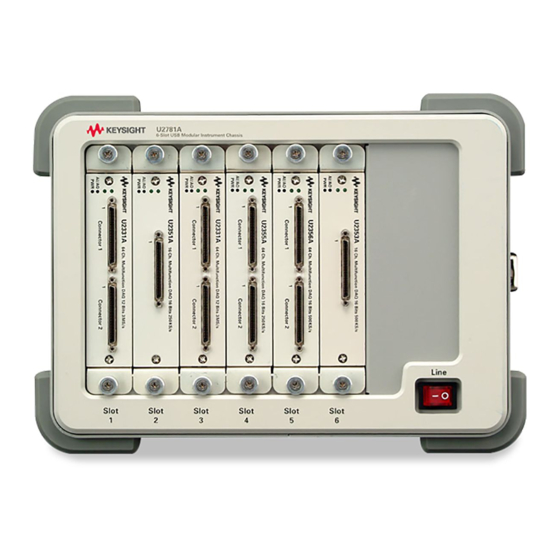
Getting Started Product Overview Product Outlook Front View Module Bumper L-Mount Kit ON/OFF switch Rear View Trigger In USB Port Trigger Out Ext 10 MHz AC Input Keysight U2781A User’s Guide... -
Page 18: Dimensions
Getting Started Dimensions 197.00 mm 270.00 mm 271.20 mm Keysight U2781A User’s Guide... -
Page 19: Standard Purchase Items Checklist
Getting Started Standard Purchase Items Checklist Inspect and verify the following items for the standard purchase of U2781A USB modular instrument chassis. If there are missing items, contact the nearest Keysight Sales Office. ✔ Power cord ✔ USB Extension Cable ✔... -
Page 20: Installations And Configurations
Getting Started Installations and Configurations If you are using the U2781A USB modular instrument chassis with the Keysight Measurement Manager, follow the step-by-step instructions as shown in the Keysight USB Modular Products and Systems Quick Start Guide. You need to install IVI-COM driver before using the U2781A Series with Keysight NOTE VEE, LabVIEW or Microsoft Visual Studio. -
Page 21: General Maintenance
1 Power off the chassis device and remove the power cord and I/O cable from the chassis. 2 Shake out any dirt that may have accumulated inside the chassis device. 3 Wipe the chassis with a dry cloth. Keysight U2781A User’s Guide... - Page 22 Getting Started THIS PAGE HAS BEEN INTENTIONALLY LEFT BLANK. Keysight U2781A User’s Guide...
- Page 23 External Trigger Out External Trigger In (Star Trigger) Simultaneous Synchronization (SSI) Simultaneous Synchronization (SSI) Chassis Temperature Monitoring Fan Speed Monitoring Identifying Modules Location This chapter provides information for better understanding of the features and functions of the U2781A USB modular instrument chassis.
-
Page 24: Features And Functions
U2781A modular instrument chassis. The modular chassis allocates housing for six USB modules with built-in power supply. The USB backplane provides a means to synchronize the modules. The key features of the U2781A USB modular instrument chassis are as follows: – Simultaneous Synchronization (SSI) – Star trigger –... -
Page 25: Usb Backplane
Trigger bus 0 ~ 7 STAR_TRIG Star trigger CLK10M 10MHz reference clock USB_VBUS USB bus power, +5 V USB_D+, USB_D– USB differential pair LBL <0..7> and LBR <0..7> Reserved pin GA0, GA1, GA2 Geographical address pin Keysight U2781A User’s Guide... -
Page 26: Figure 2-1 Usb Backplane Block Diagram
Features and Functions Figure 2-1 USB backplane block diagram Keysight U2781A User’s Guide... -
Page 27: Trigger Bus (Trig [0
Block diagram of Trigger Bus (TRIG [0..7]) and Trigger Out In addition, the trigger bus can also be used to carry out the pre-configuration of the chassis and modules before any triggering activities. Refer to Identifying Mod ules Location for more information. Keysight U2781A User’s Guide... -
Page 28: External Trigger Out
TRIGger:OUT {0|1|2|3|4|5|6|7} Table 2-2 Trigger out bits for U2300A, U2500A, and U2600A Series DAQ devices Trigger Out Function Bit-0 Time base Bit-1 Reserved Bit-2 Reserved Bit-3 A/D trigger Bit-4 Reserved Bit-5 Reserved Bit-6 Reserved Bit-7 D/A trigger Keysight U2781A User’s Guide... -
Page 29: External Trigger In (Star Trigger)
To set star trigger as the module trigger source, the following SCPI command is sent to the modules: OUTP:TRIG:SOUR STRG Star Trigger Bus Figure 2-3 Block diagram of the 10 Mhz Reference Clock and External Trigger In Keysight U2781A User’s Guide... -
Page 30: Simultaneous Synchronization (Ssi)
Figure 2-4 illustrates an example of SSI. The SSI feature should be configured using the bundled Keysight Measurement Manager (AMM). SSI allows users to set the modules as MASTER or SLAVE. The MASTER module sends the SSI signal to the slave modules via the backplane trigger bus (TRIG [0..7]). - Page 31 Connectors Connectors SSI Trigger Bus Chassis SLAVE module 1 SLAVE module 1 SLAVE module 2 SLAVE module 2 SSI Signals SSI Signals FPGA FPGA 55-pin 55-pin Connectors Connectors Figure 2-4 Synchronization between modules in the chassis Keysight U2781A User’s Guide...
-
Page 32: Single Master-Multiple Slaves
In this configuration, only one Master module is allowed to send the SSI trigger event to the receiving Slave modules. Configuration with Keysight U2300A, U2500A, and U2600A Series DAQ only When there is one or more U2300A, U2500A, or U2600A Series DAQ in the SSI configuration, SSI allows users to set only one of the modules as MASTER and others as SLAVE through AMM. -
Page 33: Figure 2-6 Single Master-Multiple Slave Triggering
Features and Functions Configuration with combination of Keysight U2300A, U2500A, U2600A Series DAQ and U2700A Series modular products With one DAQ configured as Master, all of the other U2700A Series modular devices can only be configured as Slave to receive the event of the signal as... -
Page 34: Table
M — Master, S — Slave, T0~T7 — Trigger bus (TRIG [0..7]), * — Star Trigger [a] Multiple Master is not allowed with DAQ set as Master. [b] U2700A Series modular devices should not be configured as Master. Keysight U2781A User’s Guide... -
Page 35: Multiple Master-Multiple Slaves
This configuration is only supported by U2700A Series modular products. Figure 2-7 Multiple Master–multiple Slave triggering Table 2-4 shows some examples of supported and not supported configurations. Example of configurations for multiple Master–multiple Slaves. Keysight U2781A User’s Guide... -
Page 36: Example Of Configurations For Multiple Master-Multiple Slaves
[b] Slave device not allowed to occupy two trigger lines. [c] Not allowed to have both Master and Slave configuration for a device. [d] Not allowed to have Star Trigger and Slave mode for a device. Keysight U2781A User’s Guide... -
Page 37: System Reference Clock
BNC connector. If none is found, then the internal 10 MHz clock source will be used. The SCPI command below will direct the reference clock source to the internal 10 MHz: ACQuire:RSIGnal INT Keysight U2781A User’s Guide... -
Page 38: Chassis Temperature Monitoring
USB device through an I C interface as illustrated in following figure. Figure 2-8 Block diagram of temperature monitoring and fan control The SCPI command below queries the temperature reading from the sensors in degree Celsius (°C): SYSTem:TEMPerature? {1|2} Keysight U2781A User’s Guide... -
Page 39: Fan Speed Monitoring
Features and Functions Fan Speed Monitoring The U2781A USB modular instrument chassis is also integrated with a fan speed control circuit. It is used to monitor the fan status and speed. The control circuit communicates with backplane USB device via I C interface. -
Page 40: Identifying Modules Location
Slot Address The USB modules are able to read this 3-bit data and know which slot the module is plugged in. To read the geographical address of each module, the SCPI command below is used: SYSTem:CDEScription? Keysight U2781A User’s Guide... -
Page 41: Modules Identification
Select 0 to disable the output. The modular chassis will not be triggered to send NOTE any output to the USB modules. 2 Send the following command to every module in the chassis to query each of the slot and chassis numbers. SYST:CDES? Keysight U2781A User’s Guide... - Page 42 – Do not execute the above mentioned steps when the USB modules are in the NOTE process of acquiring data. – You do not need to perform the above pre-configuration if you are using the Keysight Measurement Manager software. You are only required to press the “Refresh” button. Keysight U2781A User’s Guide...
-
Page 43: Specifications
Keysight U2781A USB Modular Instrument Chassis User’s Guide Characteristics and Specifications For the characteristics and specifications of the U2781A USB Modular Instrument Chassis, refer to the datasheet at http://literature.cdn.keysight.com/litweb/pdf/5989-9923EN.pdf. - Page 44 Characteristics and Specifications THIS PAGE HAS BEEN INTENTIONALLY LEFT BLANK. Keysight U2781A User’s Guide...
- Page 45 This information is subject to change without notice. Always refer to the Keysight website for the latest revision. © Keysight Technologies 2006 - 2017 Edition 8, June 1, 2017 Printed in Malaysia *U2781-90003* U2781-90003 www.keysight.com...
Need help?
Do you have a question about the U2781A and is the answer not in the manual?
Questions and answers