Table of Contents
Advertisement
Quick Links
Advertisement
Table of Contents

Related Manuals for Keysight U1461A


Summary of Contents for Keysight U1461A
- Page 1 Keysight U1461A Insulation Multimeter/ U1453A Insulation Tester Quick Start Guide...
- Page 2 Category IV 600 V CAT IV overvoltage protection 600 V Do not use in distribution systems with voltages higher than 600 V For further safety information details, refer to the Keysight U1461A Insulation Multimeter/U1453A Insulation Tester User’s Guide. U1461A/U1453A Quick Start Guide...
- Page 3 The descriptions and instructions in this guide apply NOTE to the U1461A Insulation Multimeter and U1453A Insulation Tester. Model U1461A appears in all illustrations. The word tester is used to represent both models. All related documents and software are available for download at www.keysight.com/find/hhTechLib.
-
Page 4: Install Or Change The Batteries
Before installing or changing the batteries, pull from a corner and stretch the orange rubber holster to remove it. Turn On the Tester Turn the rotary switch from the position to any other position to begin making measurements. U1461A/U1453A Quick Start Guide... -
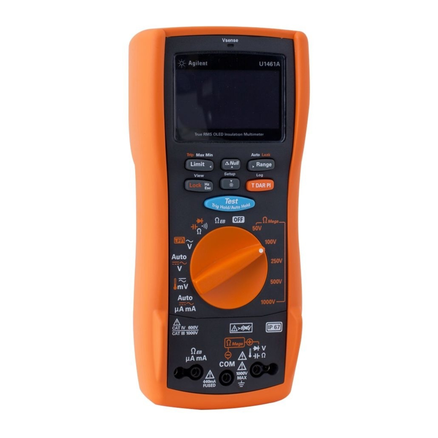
Page 5: The Tester At A Glance
The Tester at a Glance Vsense/Red LED indicator (Vsense for model U1461A) Display screen Keypad Rotary switch Input terminals IR communication port Test lead/probe holders Battery access (Under the orange rubber holster) Tilt stand Fuse access (Under the orange rubber... -
Page 6: Using The Rotary Switch
AC μA mA Remove the test leads from the measuring source or WARNING target before changing the rotary switch position. Refer to the U1461A/U1453A User’s Guide for a complete list and description of all rotary switch labels. U1461A/U1453A Quick Start Guide... -
Page 7: Using The Keypad
Hz: Displays the frequency View: Enters the Log (when the rotary switch is in review menu the V, mV (U1461A), or μA mA (U1461A) position) Esc: Discards the changes made in the Setup menu Selects the alternate... -
Page 8: Using The Input Terminals
Using the Input Terminals To avoid damaging this device, do not exceed the input WARNING limit. Rotary position Input terminals Overload protection 1000 Vrms 1000 Vrms for short circuit <0.3 A 440 mA/1000 V, 30 kA fast-acting fuse U1461A/U1453A Quick Start Guide... -
Page 9: Insulation Resistance (Ir) Test
30 V, the test is inhibited and the voltage hazard symbol ( ) is shown on the display. DO NOT perform insulation resistance test in CAUTION distribution systems with voltages higher than 600 V. Select a test voltage Remote Switch Probe U1461A/U1453A Quick Start Guide... - Page 10 2 seconds (if the Limit function is not enabled). Using the Remote Switch Probe Locking the Test for IR/EBR Tests Press once Press [Test] or [Lock] again to unlock and stop the test. U1461A/U1453A Quick Start Guide...
- Page 11 Error is shown on the display if the IR is greater NOTE than the maximum range or less than 0.001 MΩ after t1/t15/t30; if the test is interrupted by the user; or if the tester’s battery is low. Viewing Leakage Current U1461A/U1453A Quick Start Guide...
- Page 12 Setup. For more information on the Leakage Current Trip NOTE Test, Scan Trip Test, and Ramp Trip Test, refer to the respective sections in the U1461A/U1453A User’s Guide. U1461A/U1453A Quick Start Guide...
-
Page 13: Earth-Bond Resistance (Ebr) Test
If the external voltage is detected to be greater than 2 V, the test is inhibited and is shown on the display. Disconnect the tester and remove power before proceeding. Remote Switch Probe Hold > U1461A/U1453A Quick Start Guide... -
Page 14: Voltage Measurement
– select a suitable measurement range according to the AC+DC reading The symbol blinks d uring the identification The AC+DC value is shown in the secondary display U1461A/U1453A Quick Start Guide... - Page 15 (defaults to 600 V) for variable speed drive (VSD) applications. It is recommended only to use 600 V and 1000 V in the manual range for VSD testing. U1461A/U1453A Quick Start Guide...
- Page 16 Enable the LPF in the Setup to filter out higher frequencies with (AC/DC path) V, mV, μA, or mA measurements. > 1 sec. > > > 1 sec. > > > U1461A/U1453A Quick Start Guide...
-
Page 17: Current Measurement
440 mA and up to 600 mA for 120 seconds maximum. – Cool down the tester for twice the measuring time taken before proceeding to another current measurement. Refer to Voltage Measurement for more information on how the Auto function works. LOAD LOAD U1461A/U1453A Quick Start Guide... - Page 18 Measuring Voltage Frequency Measuring Current Frequency Measuring Frequency/Pulse Wid th/Duty Cycle For model U1461A only. This option must first be enabled in the Setup. Press and hold [ ] to enter the Setup. Browse to Menu 10 > % & ms and change the option from +CYCLE-D to +CYCLE-E or –CYCLE-E.
-
Page 19: Resistance Measurement
Resistance Measurement Removing Test Lead Resistance U1461A/U1453A Quick Start Guide... -
Page 20: Continuity Test
Continuity Test To avoid possible damage to your tester or to the CAUTION equipment under test, disconnect the circuit power and discharge all high-voltage capacitors before performing continuity tests. (open) (closed) U1461A/U1453A Quick Start Guide... -
Page 21: Diode Test
Press and hold [Range] to enable Auto-d iode. The NOTE Auto-diode feature will help you test both forward- and reverse-bias directions simultaneously. You do not need to change the measuring direction to identify the diode’s condition. U1461A/U1453A Quick Start Guide... -
Page 22: Capacitance Measurement
Before proceeding with capacitance measurements, first use the DC V function to confirm that the capacitor is fully discharged. – Press [Lock ] to temporarily display the cable NOTE length of the circuit under test in the secondary display. U1461A/U1453A Quick Start Guide... -
Page 23: Temperature Measurement
Temperature Measurement Do not connect the thermocouple to electrically live WARNING circuits. Doing so will potentially cause fire or electrical shock. Press and hold [Range] to remove the ambient NOTE compensation for temperature measurements. U1461A/U1453A Quick Start Guide... -
Page 24: Non-Contact Voltage Detector (Vsense)
The Vsense detector may be affected by differences in socket design, insulation thickness, and insulation type. AC Voltage Source > 1 sec. Press [Range] to change the Vsense detector’s NOTE sensitivity from HIGH SENSE to LOW SENSE. U1461A/U1453A Quick Start Guide... - Page 25 THIS PAGE HAS BEEN INTENTIONALLY LEFT BLANK. U1461A/U1453A Quick Start Guide...
- Page 26 This information is subject to change without notice. Always refer to the Keysight website for the latest revision. © Keysight Technologies 2013-2021 Edition 5, January 2021 Printed in Malaysia U1461-90001 www.keysight.com...
Need help?
Do you have a question about the U1461A and is the answer not in the manual?
Questions and answers