Table of Contents
Advertisement
Advertisement
Table of Contents
Troubleshooting

Related Manuals for Keysight U1401B


Summary of Contents for Keysight U1401B
- Page 1 Keysight U1401B Handheld Multi-Function Calibrator/Meter User’s and Service Guide...
- Page 2 FAR 27.401 or DFAR 227.7103-5 (c), as applicable in any Do not proceed beyond a WARNING technical data. notice until the indicated conditions are fully understood and met. Keysight U1401B User’s and Service Guide...
-
Page 3: Safety Symbols
Out position of a bistable push control Frame or chassis terminal In position of a bistable push control CAT II Category II 150 V overvoltage Equipotentiality 150 V protection Equipment protected throughout by double insulation or reinforced insulation Keysight U1401B User’s and Service Guide... -
Page 4: General Safety Information
Failure to comply with these precautions or with specific warnings elsewhere in this manual violates safety standards of design, manufacture, and intended use of the instrument. Keysight Technologies assumes no liability for the customer’s failure to comply with these requirements. - Page 5 – Do not substitute parts or modify equipment to avoid the danger of introducing additional hazards. Return the product to the nearest Keysight Technologies Sales and Service Office for service and repair to ensure the safety features are maintained. – Do not operate damaged equipment as the safety protection features built into this product may have been impaired, either through physical damage, excessive moisture, or any other reason.
-
Page 6: Measurement Category
Measurement Category The Keysight U1401B has a safety rating of CAT II 150 V. Measurement CAT I Measurements performed on circuits not directly connected to the AC mains. Examples are measurements on circuits not derived from the AC mains and specially protected (internal) mains-derived circuits. -
Page 7: Environmental Conditions
EM field and noise are removed or when the instrument is protected from the ambient EM field or when the instrument cabling is shielded from the ambient EM noise. Keysight U1401B User’s and Service Guide... -
Page 8: Regulatory Markings
Cet appareil ISM est conforme a la this electrical or electronic product in norme NMB-001 du Canada. domestic household waste. The CSA mark is a registered trademark of the Canadian Standards Association. Keysight U1401B User’s and Service Guide... -
Page 9: Waste Electrical And Electronic Equipment (Weee) Directive 2002/96/Ec
To return this unwanted instrument, contact your nearest Keysight Service Center, or visit http://about.keysight.com/en/companyinfo/environment/takeback.shtml for more information. Sales and Technical Support To contact Keysight for sales and technical support, refer to the support links on the following Keysight websites: – www.keysight.com/find/handheld-calibrator-meter (product-specific information and support, software and documentation updates) –... - Page 10 THIS PAGE HAS BEEN INTENTIONALLY LEFT BLANK. Keysight U1401B User’s and Service Guide...
-
Page 11: Table Of Contents
........9 Getting Started Introducing the U1401B Handheld Multi-Function Calibrator/Meter Standard Purchase Items . - Page 12 ........88 Keysight U1401B User’s and Service Guide...
- Page 13 ........138 Keysight U1401B User’s and Service Guide...
- Page 14 ........153 Characteristics and Specifications Keysight U1401B User’s and Service Guide...
- Page 15 ....86 Figure 4-6 Setting the percentage scale readout ... . .87 Keysight U1401B User’s and Service Guide...
- Page 16 ..... . 134 Figure 6-3 Fuse replacement ......135 Keysight U1401B User’s and Service Guide...
- Page 17 ... .147 Table 7-5 Calibration tests ......150 Keysight U1401B User’s and Service Guide...
- Page 18 ....154 Table 7-7 Output current calibration steps ....155 Keysight U1401B User’s and Service Guide...
-
Page 19: Getting Started
Keysight U1401B Handheld Multi-Function Calibrator/Meter User’s and Service Guide Getting Started Introducing the U1401B Handheld Multi-Function Calibrator/Meter Standard Purchase Items List of Accessories Product Overview Remote Communication This chapter contains a brief description of the U1401A Handheld Multi-Function Calibrator/Meter front panel, rotary switch, keypad, display, terminals, and rear... -
Page 20: Introducing The U1401B Handheld Multi-Function Calibrator/Meter
Getting Started Introducing the U1401B Handheld Multi-Function Calibrator/Meter The key features of the U1401B are: – Simultaneous signal generation and measurement. – DC, AC, and AC+DC voltage and current measurements. – DC voltage, DC current, and square wave outputs. – Intelligent output and standby control. -
Page 21: Standard Purchase Items
Getting Started Standard Purchase Items Verify that you have received the following items with your U1401B Handheld Multi-Function Calibrator/Meter: – Protective holster – Rechargeable battery pack (1.2 V NiMH AA × 8) – Power cord and AC power adapter – Silicone test leads –... -
Page 22: List Of Accessories
Extended test lead kit U1162A Alligator clips U1168A Standard test lead set with 4 mm test probes U1169A Standard test leads with 4 mm probe tip U5481A IR-to-USB cable U5491A Soft carrying case for handheld and accessories Keysight U1401B User’s and Service Guide... -
Page 23: Product Overview
CHARGE Charges the batteries with an external AC adapter. Enables only the measurement functions. Enables both measurement and source functions. Slide Switch — Charging indication Indicates the charging process. GREEN: Fully charged YELLOW: Charging Keysight U1401B User’s and Service Guide... -
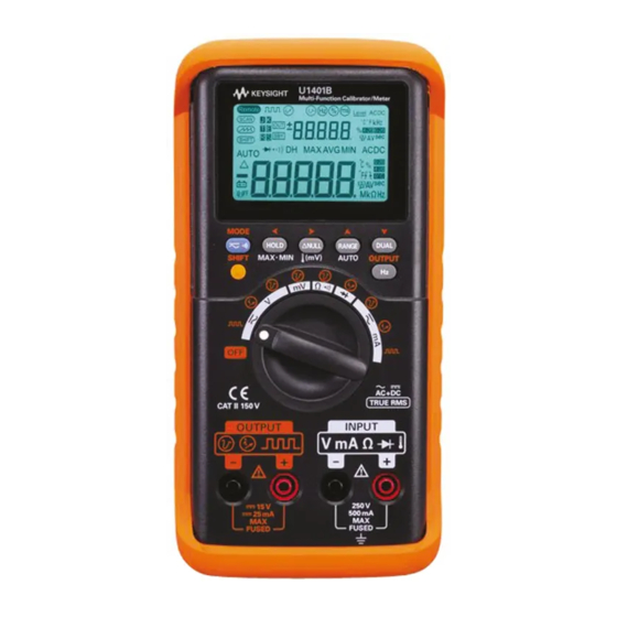
Page 24: The Front Panel At A Glance
Getting Started The front panel at a glance Display Keypad Rotary switch Terminals Figure 1-2 The front panel Keysight U1401B User’s and Service Guide... -
Page 25: The Rotary Switch At A Glance
– Constant current: ±25 mA – Constant voltage: ±1.5 V, ±15 V DC, AC, or AC+DC mV measurements or temperature Constant voltage: ±1.5 V, ±15 V measurement Resistance measurement and continuity test Constant voltage: ±1.5 V, ±15 V Keysight U1401B User’s and Service Guide... -
Page 26: The Keypad At A Glance
The operation of each key is shown below. A related annunciator appears on the display and the instrument beeps when a key is pressed. Turning the rotary switch to another position resets the present operation of the key. Figure 1-4 Keypad functions Keysight U1401B User’s and Service Guide... -
Page 27: Figure 1-5 Keypad Shifted Functions
– and secondary displays Selects frequency (Hz), duty cycle (%), or pulse Exits selection width (ms) on the primary display SHIFT Enables and disables the shifted functions of the Toggles backlight ON/OFF other keys Keysight U1401B User’s and Service Guide... - Page 28 [b] Only applicable when the instrument is in the dynamic recording mode. [c] Shifted functions. Keysight U1401B User’s and Service Guide...
-
Page 29: Table 1-5 Instructions Involving Shifted Functions
Press Press SHIFT , then press Press SHIFT , then press Press Press Press SHIFT , then press Press OUTPUT Press SHIFT , then press [a] If the shifted functions are not already enabled. Keysight U1401B User’s and Service Guide... -
Page 30: The Display At A Glance
To wake the instrument up, perform the following steps: 1 Turn the rotary switch (knob) to the OFF position; 2 Then turn the rotary switch to any position other than square wave output and press any key. Figure 1-6 Full display Keysight U1401B User’s and Service Guide... -
Page 31: Table 1-6 Description Of Display Annunciators
Square wave output Frequency (Hz), duty cycle (%), pulse width (ms), and level for square wave output Constant current output Constant voltage output Thermocouple type for temperature test. The U1401B supports K-type thermocouple only. Keysight U1401B User’s and Service Guide... - Page 32 Dynamic recording mode: Maximum value on primary display Dynamic recording mode: Average value on primary display Dynamic recording mode: Minimum value on primary display ACDC Alternating/direct current Primary display for input Input units for primary display Keysight U1401B User’s and Service Guide...
- Page 33 Positive slope for pulse width (ms) and duty cycle (%) measurement Negative slope for pulse width (ms) and duty cycle (%) measurement Percentage scale for 0 to 20 mA and 4 to 20 mA current measurement Without ambient temperature compensation Keysight U1401B User’s and Service Guide...
-
Page 34: The Terminals At A Glance
This instrument has four terminals. The two terminals for input functions are protected against overloads for the limits specified in Table 1-8. The other two terminals are for output functions, with DC 30 V overload protection. Keysight U1401B User’s and Service Guide... -
Page 35: Table 1-8 Overload Protection For The Input Terminals
250 V 5 V to 250 V AC/DC voltage range: 50 mV to 500 mV Ohm (Ω) Diode ( Temperature AC/DC current range: 250 V/ 630 mA, fast-acting fuse 50 mA to 500 mA Keysight U1401B User’s and Service Guide... -
Page 36: The Rear Panel At A Glance
Getting Started The rear panel at a glance Figure 1-8 The rear panel Keysight U1401B User’s and Service Guide... -
Page 37: Display Selection With The Hz Key
Frequency (Hz) AC+DC voltage Duty cycle (%) Pulse width (ms) AC current Frequency (Hz) AC current Duty cycle (%) Pulse width (ms) DC current Frequency (Hz) DC current Duty cycle (%) Pulse width (ms) Keysight U1401B User’s and Service Guide... - Page 38 Frequency (Hz) Current in percentage scale (0 mA to 20 mA or 4 mA to 20 mA) (0 mA to 20 mA or 4 mA to 20 mA) Duty cycle (%) Pulse width (ms) Keysight U1401B User’s and Service Guide...
-
Page 39: Display Selection With The Dual Key
Hz (DC coupling) (0 mA to 20 mA or 4 mA to 20 mA) (0 mA to 20 mA or 4 mA to 20 mA) Temperature Celsius (°C) Fahrenheit (°F) Fahrenheit (°F) Celsius (°C) Keysight U1401B User’s and Service Guide... -
Page 40: Remote Communication
The default values for baud rate, parity, data bits, and stop bit for the instrument are 9600, n, 8, and 1 respectively. 2 Make sure that the USB driver and the Keysight data logger software has been installed on your computer. -
Page 41: Figure 1-9 Ir-Usb Cable
Getting Started Figure 1-9 IR-USB cable Text side facing upward IR-USB cable Figure 1-10 IR-USB cable connection Keysight U1401B User’s and Service Guide... -
Page 42: Figure 1-11 Ir-Usb Cable
Getting Started Disconnect Connect Press this flap while moving in the direction indicated by the arrows to connect or disconnect the IR-USB cable Figure 1-11 IR-USB cable Keysight U1401B User’s and Service Guide... - Page 43 Keysight U1401B Handheld Multi-Function Calibrator/Meter User’s and Service Guide Calibrator Output Operations Enabling and Disabling the Output Constant Voltage Operation Constant Current Operation Memory Generation Square Wave Output This chapters contains detailed information on how to generate signals using the...
-
Page 44: Calibrator Output Operations
Enabling and Disabling the Output The U1401B can generate and measure signals simultaneously. Pressing the OUTPUT key disables the U1401B output by placing it in the standby mode. Pressing this key again toggles the output on. When the output is in the standby mode, the annunciator disappears and the annunciator is displayed instead. -
Page 45: Constant Voltage Operation
Calibrator Output Operations Constant Voltage Operation The U1401B can generate a constant voltage output in two different ranges, namely ±1.5 V and ±15 V. To select the constant voltage output function: 1 Turn the rotary switch to any one of the (constant voltage output) positions. -
Page 46: Constant Current Operation
Calibrator Output Operations Constant Current Operation The U1401B can generate a constant current output in the range of ±25 mA. To select the constant voltage output function: 1 Turn the rotary switch to any one of the (constant current output) positions. -
Page 47: Memory Generation
Calibrator Output Operations Memory Generation For constant voltage and current outputs, the U1401B offers two additional useful functions. One is an autoscan output that is able to generate up to 16 different steps of constant voltage or current each with its own user-defined amplitude and time interval. -
Page 48: Figure
1 is “00” second, the output level will be set to the amplitude of step 1 and the output status will be set to . If you stop the signal output in the continuous or cycle mode, the next output step will start from step 1. Keysight U1401B User’s and Service Guide... -
Page 49: Table 2-1 Default Settings For The Autoscan Output
00 sec +00.000 V 00 sec +12.000 mA 00 sec –1.5000 V 00 sec –15.000 V 00 sec +16.000 mA 00 sec +0.0000 V 00 sec +00.000 V 00 sec +20.000 mA 00 sec Keysight U1401B User’s and Service Guide... -
Page 50: Figure 2-1 Selecting Autoscan Output Mode
Calibrator Output Operations Press Press Press Figure 2-1 Selecting autoscan output mode Figure 2-2 Example of a typical autoscan output Keysight U1401B User’s and Service Guide... - Page 51 The time interval can be set within the range of 0 to 99 seconds. – Press for more than one second to directly reset the time interval and amplitude of the present step to zero. Keysight U1401B User’s and Service Guide...
-
Page 52: Autoramp Output
Select either of the two (autoramp) output modes, depending on the voltage range you require. – For current output, press MODE to cycle through ±25 mA, ±25 mA, ±25 mA output modes. Select the output mode. Keysight U1401B User’s and Service Guide... -
Page 53: Table 2-2 Default Settings For The Autoramp Output
0.33 seconds, and then the output amplitude will be maintained at the final value of the ramp signal. 5 Press OUTPUT to start the source output. The annunciator will appear on the display. Keysight U1401B User’s and Service Guide... -
Page 54: Figure 2-4 Selecting Autoramp Output Mode
When the U1401B is in the autoramp adjustment mode, the secondary display shows the amplitude of the start or end position. The first digit on the left of the primary display is used to indicate the start or end position. -
Page 55: Figure 2-6 Defining The Autoramp Output
2 Press OUTPUT to save the settings. Start amplitude End amplitude Press MODE Press MODE Start position 1 ~ 999 steps 1 to 99 steps End position Figure 2-6 Defining the autoramp output Keysight U1401B User’s and Service Guide... -
Page 56: Square Wave Output
1 Press SHIFT to access the shifted operations of the keypad. The annunciator will appear on the display. 2 Press MODE to select frequency adjustment. The annunciator will appear on the display. 3 Select the frequency by pressing 4 Press OUTPUT to output the signal. Keysight U1401B User’s and Service Guide... - Page 57 The amplitude can be set as +5 V, ±5 V, +12 V, or ±12 V. To adjust the amplitude: 1 Press MODE to select amplitude adjustment. The Level annunciator will appear on the display. 2 Press to select the amplitude. Keysight U1401B User’s and Service Guide...
-
Page 58: Figure 2-7 Parameter Selection For Square Wave Output
Calibrator Output Operations Press MODE Press MODE Press MODE Press MODE Figure 2-7 Parameter selection for square wave output Keysight U1401B User’s and Service Guide... - Page 59 Keysight U1401B Handheld Multi-Function Calibrator/Meter User’s and Service Guide Making Measurements Measuring Voltage Measuring Current Measuring Temperature Measuring Resistance and Testing Continuity Alerts and Warning During Measurement Math Operations Triggering Operations This chapter contains the detailed information on how measurements are taken...
-
Page 60: Making Measurements
Making Measurements Measuring Voltage The U1401B performs true-rms AC measurements that are accurate for square waves without any DC offset. Make sure that the terminal connections are correct for a particular WARNING measurement before making the measurement. To avoid damaging the U1401A, do not exceed the rated input limit. -
Page 61: Figure 3-1 Dc Voltage Measurement
Making Measurements Figure 3-1 DC voltage measurement Keysight U1401B User’s and Service Guide... -
Page 62: Measuring Ac Voltage
AC voltage measurement. 3 Connect the red and black test leads to the positive and negative input terminals respectively (Figure 3-2). 4 Probe the test points and read the display. Figure 3-2 AC voltage measurement Keysight U1401B User’s and Service Guide... -
Page 63: Measuring Current
3 Connect the red and black test leads to the positive and negative input terminals respectively. 4 Probe the test points in series with the circuit and read the display (see Figure 3-3). Figure 3-3 DC current (mA) measurement Keysight U1401B User’s and Service Guide... -
Page 64: Percentage Scale Of Dc Ma Measurement
5 Probe the test points in series with the circuit and read the display. The inset display in Figure 3-3 shows the percentage scale reading representing 20 mA in the range of 4 mA to 20 mA. Keysight U1401B User’s and Service Guide... -
Page 65: Measuring Temperature
3 Press and hold for more than 1 second to select temperature measurement. 4 Plug the thermocouple adapter (with the thermocouple probe connected to it) into the positive and negative input terminals (Figure 3-4 on page 66). Keysight U1401B User’s and Service Guide... -
Page 66: Figure 3-4 Surface Temperature Measurement
3 After a constant reading is obtained, press to set the reading as the relative reference temperature. 4 Touch the surface to be measured with the thermocouple probe. 5 Read the display for the relative temperature. Figure 3-4 Surface temperature measurement Keysight U1401B User’s and Service Guide... -
Page 67: Measuring Resistance And Testing Continuity
Table 3-1 Measurement ranges for audible continuity Measurement range Resistance threshold 500.00 Ω 10 Ω 5.0000 kΩ 100 Ω 50.000 kΩ 1 kΩ 500.00 kΩ 10 kΩ 5.0000 MΩ 100 kΩ 50.000 MΩ 1 MΩ Keysight U1401B User’s and Service Guide... -
Page 68: Figure 3-5 Resistance Measurement
Making Measurements Figure 3-5 Resistance measurement Press Figure 3-6 Enabling and disabling the continuity test Keysight U1401B User’s and Service Guide... -
Page 69: Alerts And Warning During Measurement
This instrument provides an overload alert for voltage measurement in both auto and manual range modes. The instrument starts to beep periodically once the measured voltage exceeds 251 V. Immediately remove the test leads from the source being measured. Keysight U1401B User’s and Service Guide... -
Page 70: Math Operations
– The recording interval in manual range is approximately 0.067 seconds. – The average value is the true average of all measured values taken since the recording mode was activated. Keysight U1401B User’s and Service Guide... -
Page 71: Figure 3-7 Dynamic Recording Mode
Making Measurements Press Press Press Press Press Press Press Press Figure 3-7 Dynamic recording mode Keysight U1401B User’s and Service Guide... -
Page 72: Relative (Zero)
– For a DC voltage measurement, the thermal effect will influence the accuracy. Use the relative function to offset the thermal effect. Short the test leads and press when the displayed value has settled down to a stable state. Press Figure 3-8 Relative (zero) mode Keysight U1401B User’s and Service Guide... -
Page 73: Triggering Operations
2 Press the key again to trigger another new measured value and update the display. The DH annunciator will flash momentarily before the new update. 3 Press for more than one second to exit this mode. Press Figure 3-9 Data hold mode Keysight U1401B User’s and Service Guide... -
Page 74: Refresh Hold (Auto Trigger)
500 counts. For resistance and diode measurements, the held value will not be updated if the reading is OL or open. For all measurements, the held value will not be updated if the reading cannot reach a stable state. Keysight U1401B User’s and Service Guide... -
Page 75: Ms Peak Hold
4 While the peak hold mode is on, you can press at any time to restart the peak value measurement. Press Press Press Press to change to restart range Press Figure 3-10 1 ms peak hold mode Keysight U1401B User’s and Service Guide... - Page 76 Making Measurements THIS PAGE HAS BEEN INTENTIONALLY LEFT BLANK. Keysight U1401B User’s and Service Guide...
- Page 77 Keysight U1401B Handheld Multi-Function Calibrator/Meter User’s and Service Guide Changing the Default Settings Entering the Setup Mode Available Setting Options This chapter describes how to change the default settings of the U1401B.
-
Page 78: Changing The Default Settings
To enter the setup mode, perform the following steps: 1 Turn the instrument off. 2 From the OFF position, turn the rotary switch to any non-OFF position while pressing and holding Press and hold Turn on Figure 4-1 Entering the setup mode Keysight U1401B User’s and Service Guide... - Page 79 80 for details on the available options. c Press to save the changes. These parameters will remain in the non-volatile memory. 4 Press SHIFT for more than one second to exit the setup mode. Keysight U1401B User’s and Service Guide...
-
Page 80: Available Setting Options
8bit (Stop bit is communication with a PC (remote control) always 1bit) PArtY Parity En, odd, or Sets even, odd, or no parity check for remote nonE nonE communication with a PC (remote control) Keysight U1401B User’s and Service Guide... -
Page 81: Setting The Data Hold/Refresh Hold Mode
– To enable the refresh hold mode (automatic trigger), set the variation count within the range of 100 to 1000. Once the variation of the measured value exceeds this preset variation count, the refresh hold mode will be ready to trigger and update a new value. Keysight U1401B User’s and Service Guide... -
Page 82: Figure 4-2 Setting The Data Hold Or Refresh Hold Mode
Changing the Default Settings Press Press Press Press Press Figure 4-2 Setting the data hold or refresh hold mode Keysight U1401B User’s and Service Guide... -
Page 83: Setting The Temperature Unit
– Celsius (°C) on the primary display and Fahrenheit (°F) on the secondary display (for dual display setting). – Fahrenheit only (°F on the primary display). – Fahrenheit (°F) on the primary display and Celsius (°C) on the secondary display (for dual display setting). Keysight U1401B User’s and Service Guide... -
Page 84: Figure 4-3 Setting The Temperature Unit
Changing the Default Settings Press Press SHIFT for more than one second to enable temperature unit menu item Press Press Press Press Figure 4-3 Setting the temperature unit Keysight U1401B User’s and Service Guide... -
Page 85: Setting The Beeper Frequency
The beeper frequency can be set to 4800 Hz, 2400 Hz, 1200 Hz, or 600 Hz. “OFF” means the beeper is disabled. Press Press Press Press Press Press Figure 4-4 Setting the beeper frequency Keysight U1401B User’s and Service Guide... -
Page 86: Setting The Minimum Measurable Frequency
This setting will influence the measurement rates for frequency, duty cycle, and pulse width. The typical measurement rate as defined in the general specifications is based on a minimum frequency of 1 Hz. Press Press Press Press Figure 4-5 Setting the minimum frequency Keysight U1401B User’s and Service Guide... -
Page 87: Setting The Percentage Scale Readout
For example, a 25% readout represents DC 8 mA for the 4 mA to 20 mA range, or DC 5 mA for the 0 mA to 20 mA range. You may choose between the two available ranges. Press Press Press Figure 4-6 Setting the percentage scale readout Keysight U1401B User’s and Service Guide... -
Page 88: Setting The Print Mode
In this mode, the instrument automatically and continuously sends the latest data to the host, but does not accept any commands from the host. The annunciator flashes during the Print operation. Press Press Press Figure 4-7 Setting the print mode for remote control Keysight U1401B User’s and Service Guide... -
Page 89: Setting The Echo Mode
Setting this feature on enables the return of characters to a PC in remote communication, which is useful when developing PC programs with SCPI commands. – This mode is for internal use by Keysight Technologies only. NOTE – During normal operation, it is recommended that you disable this function. -
Page 90: Setting The Data Bit
The number of data bits (data width) for remote communication with a PC can be set to either 8 bits or 7 bits. There is only one stop bit, which cannot be changed. Press Press Press Figure 4-9 Setting the data bit for remote control Keysight U1401B User’s and Service Guide... -
Page 91: Setting The Parity Check
Setting the parity check The parity check for remote communication with a PC can be set to either none, even, or odd. Press Press Press Press Figure 4-10 Setting the parity check for remote control Keysight U1401B User’s and Service Guide... -
Page 92: Setting The Baud Rate
The baud rate used in the remote communication with a PC can be set as 2400 Hz, 4800 Hz, 9600 Hz, or 19200 Hz. Press Press Press Press Press Figure 4-11 Setting the baud rate for remote control Keysight U1401B User’s and Service Guide... -
Page 93: Setting The Display Backlight Timer
The display backlight timer can be set from 1 to 99 seconds. The backlight turns off automatically after the set period. “OFF” means the backlight will not turn off automatically. Press Press Press Press Press Figure 4-12 Setting the display backlight timer Keysight U1401B User’s and Service Guide... -
Page 94: Setting The Power Saving Mode
When the auto power-off feature is disabled, the annunciator will not be shown on the display. The instrument will remain on until you manually turn the rotary switch to the OFF position, or until the batteries run flat. Keysight U1401B User’s and Service Guide... -
Page 95: Figure 4-13 Setting The Auto Power-Off Mode
Changing the Default Settings Press Press Press Press Press Figure 4-13 Setting the auto power-off mode Keysight U1401B User’s and Service Guide... - Page 96 Changing the Default Settings THIS PAGE HAS BEEN INTENTIONALLY LEFT BLANK. Keysight U1401B User’s and Service Guide...
- Page 97 Simulation Mode for mA Output Measuring a Pressure Transducer Zener Diode Test Diode Test Bipolar Junction Transistor (BJT) Test Junction Field-Effect Transistor (JFET) Switch Test Operational Amplifier Verification 2-Wire Transmitter Verification Frequency Transmitter Verification This chapter describes some application examples for the U1401B.
-
Page 98: Application Examples
You can use autoscan to test the loop with varying levels of current output. Refer Chapter 2, “Autoscan output” on page 47 for more information on the memory default values. Keysight U1401B User’s and Service Guide... -
Page 99: Figure 5-1 Testing A 4 Ma To 20 Ma Current Loop With The Source
Application Examples Black Figure 5-1 Testing a 4 mA to 20 mA current loop with the source mode Keysight U1401B User’s and Service Guide... -
Page 100: Simulation Mode For Ma Output
5 Set the current level of the calibrator between 0 mA and 20 mA. Do not set a negative current output value. 6 Press OUTPUT to output the test current. This connection can be used for any loop voltage from 12 V to 30 V. Keysight U1401B User’s and Service Guide... -
Page 101: Figure 5-2 Ma Output Simulation
Application Examples Do not apply an external voltage exceeding 30 V across the output terminals CAUTION of the instrument. Yellow Black Figure 5-2 mA output simulation Keysight U1401B User’s and Service Guide... -
Page 102: Simulating A 2-Wire Transmitter On A Current Loop
Application Examples Simulating a 2-wire transmitter on a current loop The special yellow test lead supplied with the U1401B can also be used for simulating a 2-wire transmitter. This lead is used in place of the red lead (which is used in most other applications). -
Page 103: Figure 5-3 Use The Yellow Test Lead To Perform The 2-Wire Transmitter Simulation
Application Examples Input Excitation source Yellow Black Always use yellow test lead to perform mA simulation Figure 5-3 Use the yellow test lead to perform the 2-wire transmitter simulation Keysight U1401B User’s and Service Guide... -
Page 104: Measuring A Pressure Transducer
0 PSIG to 15 PSIG 100 mV 0 PSIG to 30 PSIG 80 mV 0 PSIG to 60 PSIG 60 mV 0 PSIG to 100 PSIG 100 mV 0 PSIG to 150 PSIG 60 mV Keysight U1401B User’s and Service Guide... -
Page 105: Figure 5-4 Pressure Transducer Measurement
Application Examples White Green Lead wires 1 - Red 2 - White Out+ 3 - Black V– 4 - Green Out– Figure 5-4 Pressure transducer measurement Keysight U1401B User’s and Service Guide... -
Page 106: Zener Diode Test
5 Output a constant current of +1 mA, then measure the forward voltage of the zener diode. 6 Output a constant current of –1 mA, then measure the breakdown voltage of the zener diode. Keysight U1401B User’s and Service Guide... -
Page 107: Figure 5-5 Zener Diode Test
Application Examples Figure 5-5 Zener diode test Keysight U1401B User’s and Service Guide... -
Page 108: Diode Test
2.1 V) accompanied by a beep. In step 4, OL is indicated. – Shorted: A voltage drop of nearly 0 V is indicated in both directions, and the instrument will beep continuously. – Open: OL is indicated in both directions. Keysight U1401B User’s and Service Guide... -
Page 109: Figure 5-6 Diode Test
Application Examples Forward bias Reverse bias Black Black Figure 5-6 Diode test Keysight U1401B User’s and Service Guide... -
Page 110: Bipolar Junction Transistor (Bjt) Test
There are two types of BJT depending on polarity: PNP type and NPN type. It is recommended that you obtain the specific data sheet from the manufacturers. You can also use the U1401B to identify the polarity and terminals of a BJT by following the procedure below: 1 Turn the rotary switch to the position. -
Page 111: Table 5-2 Base Terminal According To Probe Test
Table 5-3 Polarity and terminals if Pin 3 is the base Pins Terminals >V Test leads Type Red/Black 0.6749 V 0.6723 V 0.6723 V 0.6749 V Black/Red 0.6749 V 0.6723 V 0.6723 V 0.6749 V Keysight U1401B User’s and Service Guide... -
Page 112: Table 5-4 Polarities And Terminals If Pin 2 Is The Base
Red/Black 0.6749 V 0.6723 V 0.6723 V 0.6749 V Black/Red 0.6749 V 0.6723 V 0.6723 V 0.6749 V Another common type of transistor is the TO-3 package as shown in Figure 5-8 page 113. Keysight U1401B User’s and Service Guide... -
Page 113: Figure 5-8 To-3 Transistor
According to the previous procedure, pin 2 is the base. Table 5-6 Polarity and terminals if Pin 2 is the base Pins Terminals >V Test leads Type Red/Black 0.5702 V 0.5663 V Keysight U1401B User’s and Service Guide... -
Page 114: Determining Transistor H Fe
6 Output a constant current of -0.500 mA (this is I 7 Read the measured current value (this is I The transistor h is calculated as the ratio of I over I Keysight U1401B User’s and Service Guide... - Page 115 Application Examples = 152 = 300 = Current source = Meter reading Figure 5-9 Determining transistor h Keysight U1401B User’s and Service Guide...
-
Page 116: Junction Field-Effect Transistor (Jfet) Switch Test
There are two types of JFET depending on the channel type: p-channel and n-channel. It is recommended that you obtain the specific data sheet from the manufacturers. You can also use the U1401B to identify a JFET by following the procedure below: 1 Turn the rotary switch to the position. -
Page 117: Table 5-7 Gate Terminal According To Probe Test
If R increases when V is a negative value, then it is an n-channel JFET. On the other hand, if R increases when V is a positive value, then it is a p-channel JFET. Keysight U1401B User’s and Service Guide... -
Page 118: Figure 5-11 N- Channel Jfet
118). 5 Observe at what point the resistance reading becomes OL; the voltage bias level at that point would be the cutoff voltage for the n-channel JFET. Figure 5-11 N- Channel JFET Keysight U1401B User’s and Service Guide... -
Page 119: Figure 5-12 P- Channel Jfet
119). 5 Observe at what point the resistance reading becomes OL; the voltage bias level at that point would be the cutoff voltage for the p-channel JFET. Figure 5-12 P- Channel JFET Keysight U1401B User’s and Service Guide... -
Page 120: Operational Amplifier Verification
4 Connect the red and black alligator leads to the positive and negative output terminals respectively. 5 Connect the operational amplifier as shown in Figure 5-13. 6 Use a DC power supply with +15 V and –15 V outputs to power the operational amplifier. Keysight U1401B User’s and Service Guide... -
Page 121: Figure 5-13 Current-To-Voltage Converter
7 Feed a constant current of +00.000 mA into the operational amplifier and measure the offset voltage, V 8 Gradually increase the U1401B output current from +00.000 mA to +12.000 mA while monitoring the output voltage of the operational amplifier. -
Page 122: Voltage-To-Current Converter
6 Use a DC power supply with +15 V and –15 V outputs to power the operational amplifier. 7 Gradually increase the U1401B output voltage from +00.000 mV to +06.000 V while measuring the output voltage of the operational amplifier. You will find the output voltage increasing correspondingly from around +00.000 V to... -
Page 123: Integrator: Square Wave To Triangle Wave Conversion
3 Connect the operational amplifier as shown in Figure 5-15 on page 124. 4 Use a DC power supply with +15 V and –15 V outputs to power the operational amplifier. 5 Use an oscilloscope to monitor the output waveform. Keysight U1401B User’s and Service Guide... -
Page 124: Figure 5-15 Square Wave To Triangular Wave Conversion
6 Set the square wave duty cycle to 50.00% and its amplitude to 5 V. 7 Output the square wave. 8 Select a different frequency and vary the duty cycle to further understand the characteristics of the integrator. Figure 5-15 Square wave to triangular wave conversion Keysight U1401B User’s and Service Guide... -
Page 125: 2-Wire Transmitter Verification
5 The supply can be set to any voltage up to +15 V. 6 Press OUTPUT to output the excitation voltage. 7 The instrument display will indicate a transmitter output current if an input signal is present. Keysight U1401B User’s and Service Guide... -
Page 126: Figure 5-16 Verifying A Two-Wire Transmitter
Application Examples Black Figure 5-16 Verifying a two-wire transmitter Keysight U1401B User’s and Service Guide... -
Page 127: Frequency Transmitter Verification
3 Set the output frequency to 150 Hz and duty cycle to 50%. 4 Connect the probe leads between the input terminals of the U1401B and the output terminals of the transducer. 5 Connect the alligator leads between the output terminals of the U1401B and the input terminals of the transducer. -
Page 128: Figure 5-17 Verifying A Frequency Transmitter
Application Examples Figure 5-17 Verifying a frequency transmitter Keysight U1401B User’s and Service Guide... -
Page 129: Maintenance
Keysight U1401B Handheld Multi-Function Calibrator/Meter User’s and Service Guide Maintenance Maintenance This chapter will help you troubleshoot the U1401B for faults. -
Page 130: General Maintenance
Wipe the contacts in each terminal with a clean swab moistened in alcohol. 4 Make sure the instrument has dried completely before using it. Keysight U1401B User’s and Service Guide... -
Page 131: Battery Replacement
2 Slide the cover to the left, pull it up, and remove it. See Figure 6-1. 3 It is recommended that you replace all the batteries. 4 To close the battery cover, reverse the procedures above. Keysight U1401B User’s and Service Guide... -
Page 132: Figure 6-1 Battery Replacement
Maintenance Replace all Loosen the screw batteries Slide the cover to the left side Figure 6-1 Battery replacement Keysight U1401B User’s and Service Guide... -
Page 133: Recharging The Batteries
4 The red light indicates that the batteries are being recharged. 5 When the batteries have been fully recharged, the green light turns on. Remove the AC adapter and set the slide switch at the M or M/S position. Keysight U1401B User’s and Service Guide... -
Page 134: Fuse Replacement
5 Gently remove the defective fuse by prying one end of the fuse loose and sliding it out of the fuse bracket. 6 Replace it with a new fuse of the same size and rating. Make sure the new fuse is centered in the fuse holder. Keysight U1401B User’s and Service Guide... -
Page 135: Figure 6-3 Fuse Replacement
Size Type 2110-1464 630 mA/ 250 V 5 mm x 20 mm Fast-blow ceramic-type 2110-1463 63 mA/ 250 V 5 mm x 20 mm Slow-blow UL/VDE Fuse 2 Fuse 1 Figure 6-3 Fuse replacement Keysight U1401B User’s and Service Guide... -
Page 136: Troubleshooting
When servicing the instrument, use only the specified replacement parts. Table 6-2 will assist you in identifying some of the basic problems. Keysight U1401B User’s and Service Guide... -
Page 137: Table 6-2 Troubleshooting
– Check the baud rate, parity, data bit, and stop bit (default settings: 9600, n, 8, 1) – Install the driver for IR-USB on your PC Keysight U1401B User’s and Service Guide... -
Page 138: Replacement Parts
This section contains information for ordering replacement parts for the U1401B. Table 6-3 includes a brief description of each replacement part with its corresponding part number. You may find the latest U1401B parts list in the Keysight Test and Measurement NOTE Parts Catalog (http://www.keysight.com/find/parts). To order replacement parts Not all parts listed are available as field-replaceable parts. - Page 139 Keysight U1401B Handheld Multi-Function Calibrator/Meter User’s and Service Guide Performance Tests and Calibration Calibration Overview Recommended Test Equipment Performance Verification Tests Adjustment Considerations Adjustment Procedures This chapter contains the performance test procedures and adjustment procedures.
-
Page 140: Performance Tests And Calibration
EEPROM memory will not change even when the power is switched off. Keysight Technologies’ calibration services When your instrument is due for calibration, contact your local Keysight Service Center to inquire about recalibration services. Calibration interval A one-year calibration interval is adequate for most applications. -
Page 141: Other Recommendations For Calibration
Other recommendations for calibration Specifications are only guaranteed within the specified period from the last calibration. Keysight recommends that readjustment should be performed during the calibration process for best performance. This will ensure that the Handheld Multi-Function Calibrator/Meter remains within its specifications. This calibration criterion provides the best long-term stability. -
Page 142: Recommended Test Equipment
<1/5 instrument 1 year spec Frequency Keysight 33250A <1/5 instrument 1 year spec Temperature Fluke 5520A <1/5 instrument 1 year spec Duty Cycle Fluke 5520A <1/5 instrument 1 year spec Diode Fluke 5520A <1/5 instrument 1 year spec Keysight U1401B User’s and Service Guide... -
Page 143: Performance Verification Tests
100.00 Hz 0.39~99.60% 0.3~99.6% ±5 V AC 4.9586 V ±12 V AC 11.959 V Table 7-2 is for reference only. Refer to Chapter 8, “Characteristics and Specifications” on page 157 for the detailed specifications. Keysight U1401B User’s and Service Guide... -
Page 144: Input Performance Verification
50 mVrms ±0.39 mVrms output terminals of the @ 45 Hz Press to select AC. calibrator to the U1401B input 50 mVrms ±0.39 mVrms terminals. @ 5 kHz 50 mVrms ±0.79 mVrms @20 kHz Keysight U1401B User’s and Service Guide... - Page 145 @ 16 mV Press to select frequency. calibrator to the U1401B input 100 kHz 20 kHz ±7 Hz terminals. @ 16mV 200 kHz 200 kHz ±30 kHz @ 24 mV Keysight U1401B User’s and Service Guide...
- Page 146 0.05 A ±0.5 mA @ 50 Hz 0.45 A ±2.9 mA @ 60 Hz Connect a diode to the U1401B 1.9 V ±1.45 mV Turn the rotary switch to input terminals in forward bias position. Turn the rotary switch to mV.
-
Page 147: Output Performance Verification
53131A (10 kHz) one of the positions. Universal Counter. Frequency 600 Hz ±0.04 Hz (1 kHz) Duty cycle 5 V, 25% ±0.203% (0.39% to @150 Hz 99.60%) 5 V, 75% ±0.208% @ 150 Hz Keysight U1401B User’s and Service Guide... -
Page 148: Adjustment Considerations
K-type thermocouple connected between the instrument and the calibration source. Do not turn off the instrument during calibration. This may delete the CAUTION calibration memory for the present function. Keysight U1401B User’s and Service Guide... -
Page 149: Adjustment Procedures
The secondary display will now show the Offset or Gain values. 11 Press to complete the calibration tests. 12 Repeat steps 5 through 10 for each adjustment point. 13 To exit the calibration mode, press for more than one second. Keysight U1401B User’s and Service Guide... -
Page 150: Table 7-5 Calibration Tests
50 mV @ 1 kHz 5 mV 5 mV 5.000 mV mV. Press 45 mV 45 mV 45.000 mV select AC. 500 mV @ 1 kHz 50 mV 50 mV 50.00 mV 450 mV 450 mV 450.00 mV Keysight U1401B User’s and Service Guide... - Page 151 Dual banana plug with Short copper wire shorted between 2 terminals 450 kΩ 450 kΩ 450.00 kΩ 5 MΩ Short Dual banana plug with Short copper wire shorted between 2 terminals 4.5 MΩ 4.5 MΩ 4.5000 MΩ Keysight U1401B User’s and Service Guide...
- Page 152 3 Plug a K-type thermocouple into the input terminal. Feed in the reference input signal that represents 0 C and wait for 10 minutes. 4 Press to finish the temperature calibration. Keysight U1401B User’s and Service Guide...
-
Page 153: Output Calibration
CAL-0 value recorded above. 4 Press MODE to finish the CAL-0 and CAL-1 calibration. After finishing the CAL-0 and CAL-1 calibration procedures, the instrument will automatically enter the 1.5 V output calibration mode. Keysight U1401B User’s and Service Guide... - Page 154 1.5 V +1.1000 V –1.1000 V +00.000 V 15 V +11.000 V –11.000 V At the end of the last calibration step, the primary display will show “PASS” after the MODE button is pressed. Keysight U1401B User’s and Service Guide...
- Page 155 Current range Calibration step Output current value +00.000 mA 25 mA +11.000 mA –11.000 mA At the end of the last calibration step, the primary display will show “PASS” after the MODE button is pressed. Keysight U1401B User’s and Service Guide...
- Page 156 Performance Tests and Calibration THIS PAGE HAS BEEN INTENTIONALLY LEFT BLANK. Keysight U1401B User’s and Service Guide...
-
Page 157: Characteristics And Specifications
Keysight U1401B Handheld Multi-Function Calibrator/Meter User’s and Service Guide Characteristics and Specifications For the characteristics and specifications of the U1401B Handheld Multi-Function Calibrator/Meter, refer to the datasheet at http://literature.cdn.keysight.com/ litweb/pdf/5990-3459EN.pdf. - Page 158 Characteristics and Specifications THIS PAGE HAS BEEN INTENTIONALLY LEFT BLANK. Keysight U1401B User’s and Service Guide...
- Page 159 This information is subject to change without notice. Always refer to the Keysight website for the latest revision. © Keysight Technologies 2009-2017 Edition 15, July 28, 2017 Printed in Malaysia *U1401-90055* U1401-90055 www.keysight.com...
Need help?
Do you have a question about the U1401B and is the answer not in the manual?
Questions and answers