Table of Contents
Advertisement
Quick Links
Advertisement
Table of Contents

Related Manuals for Planet Networking & Communication BSP-360


Summary of Contents for Planet Networking & Communication BSP-360
- Page 2 Industrial Renewable Energy 4-Port 10/100/1000T 802.3at PoE+ Managed Ethernet Switch BSP-360 Quick Installation Guide...
- Page 3 Safety Precautions Please read the following before using: 1. All electrical work must be done in accordance with local, and/or international electrical codes. 2. Before installing or using this device, read all instructions and cautionary marking located in (or on) this guide, the controller, the batteries, PV (Photovol- taic) array and any other device used.
-
Page 4: Table Of Contents
Table of Contents 1. Package Contents ..................4 2. Requirements ..................... 5 3. Hardware Introduction ................6 3.1 Front Panel ..................6 3.2 LED Indicators..................7 3.3 Upper Panel ..................8 4. Hardware Installation .................10 5. Web Management ..................16 6. Customer Support ..................18 Appendix A: Recommended Use of the Connected Wires ........19 Appendix B: Recommended Settings for Different Batteries ........20... -
Page 5: Package Contents
1. Package Contents Thank you for purchasing PLANET Industrial Renewable Energy Managed PoE Switch, BSP-360. Open the box of the BSP-360 and carefully unpack it. The box should contain the following items: 1 x BSP-360 1 x Quick Installation Guide... -
Page 6: Requirements
2. Requirements PLANET BSP-360 provides a remote login interface for management purposes. The following equipment is necessary for further management: Workstation is installed with Ethernet NIC (Network Interface Card) Choice of Internet browsers includes Windows XP/2003, Vista, Windows 7, Windows 8, Windows 10, MAC OS X, Linux, Fedora, Ubuntu or other platforms compatible with TCP/IP protocols. -
Page 7: Hardware Introduction
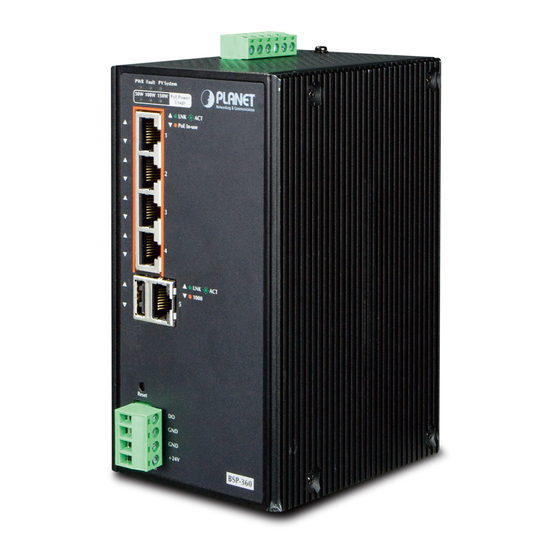
3. Hardware Introduction 3.1 Front Panel The front panel of the BSP-360 consists of 5 auto-sensing 10/100/1000Mbps Ethernet RJ45 ports and one USB interface. The LED Indicators are also located on the RJ45 ports of the BSP-360. PWR Fault PV System... -
Page 8: Led Indicators
3.2 LED Indicators System Color Function Green To indicate BSP-360 has power. Slow To indicate the PV is disconnected. Blinks Fast To indicate the battery voltage is less than the Fault Green Blinks value for low voltage disconnection. To indicate bad battery, over-current or short-circuit. -
Page 9: Upper Panel
3.3 Upper Panel The upper panel of the BSP-360 consists of one terminal block connector with PV and battery power inputs. 1 2 3 4 5 6 Figure 3-2 Upper Panel The input voltage range of each interface is shown as follows:... - Page 10 Battery In/Out 24V DC 24V DC 1 2 3 4 5 6 Battery Figure 3-4 Battery In/Out The wire gauge for the terminal block should be in the range from 14 to 24 AWG. Note DO Connectors Level 0: -24V~2.1V (±0.1V) Level 1: 2.1V~24V (±0.1V) 1 2 3 4 5 6 5~24VDC...
-
Page 11: Hardware Installation
4. Hardware Installation The following section describes the hardware installation of the BSP-360. Before connecting any network device to the BSP-360, read this chapter carefully. CAM1 CAM2 CAM3 Solar PV Turbine Battery BSP-360 Wireless CPE/AP Media Converter/ Ethernet Switch DC Powered Device... - Page 12 2. Connect the positive electrode of the battery to the terminal for the positive electrode of the battery on the BSP-360. 3. After the battery is well connected to the BSP-360, the PWR LED will be ON and System LED will slowly blink, and Fault LED will slowly blink for PV not connected.
- Page 13 2. Connect the positive electrode of the PV panel to the terminal for the positive electrode of the PV panel on the BSP-360. 3. After the PV is well connected to the BSP-360 and providing 24V or above voltage, the System LED will blink fast for battery charge if the battery is not full.
- Page 14 Step 4. Connect 802.3af/802.3at PoE Device 802.3af/at PoE Device 1. Connect the PoE devices to ports 1~4 on the BSP-360. 2. Check the PoE-in-Use LED. If the network devices such as PoE camera and PoE wireless AP are powered, the PoE-in-use LED will turn ON and Link/Act LED will blink for a successful connection or data receiving.
- Page 15 Step 5. Wiring the DC Outputs Please follow the steps below to insert the power wires for DC power required equipment. 1. Please find the terminal block connector with two DC power outputs shown below: 2. Insert the Positive and Negative DC wires into the V+ and V- terminals, respec- tively;...
- Page 16 Please ensure the output voltage is correct for remote device. Otherwise, it will damage your remote device. Step 6. Connect to PC RJ45/UTP Cable IP Address: 192.168.0.x IP Address: 192.168.0.100 After completing the above 6 steps, the BSP-360 is ready for service.
-
Page 17: Web Management
5. Web Management The following shows how to start up the Web Management of the BSP-360. Note the BSP-360 is configured through an Ethernet connection. Please make sure the manager PC must be set to the same IP subnet address. - Page 18 DC IN, Battery and Power Consumption. Step 4. The Switch Menu on the left of the Web page lets you access all the functions and status the BSP-360 provides. Now, you can use the Web management interface to continue the Switch management.
-
Page 19: Customer Support
PLANET web site first to check if it could solve your issue. If you need more support information, please contact PLANET switch support team. Switch support team mail address: support_switch@planet.com.tw BSP-360 User’s Manual: http://www.planet.com.tw/en/support/download.php?type1=22153&model=48944& type=3 BSP-360 PV&BAT Calculation: http://www.planet.com.tw/en/support/faq.php?key=%5BBSP-360%5D%20... -
Page 20: Appendix A: Recommended Use Of The Connected Wires
Appendix A: Recommended Use of the Connected Wires (Applicable to the system with voltage attenuation less than 3%) The following table is applicable to the applications in the system. Distance in feet ( meters ) Amps 24 AWG 22 AWG 20 AWG 18 AWG 16 AWG... -
Page 21: Appendix B: Recommended Settings For Different Batteries
Appendix B: Recommended Settings for Different Batteries We suggest Nickel-cadmium battery and Lead-acid battery for BSP-360. You could set the Battery type at Battery Management on the web. Description Specifications Battery type Nickel-cadmium Battery System voltage Maximum input voltage 45V DC Output voltage for load Equal to battery’s voltage...
Need help?
Do you have a question about the BSP-360 and is the answer not in the manual?
Questions and answers