
Related Manuals for Laird BT800 series


Summary of Contents for Laird BT800 series
- Page 1 Bluetooth v4.0 Dual-Mode USB HCI Module Hardware Integration Guide (HIG) Version 0.2 BT800 Series Americas: +1-800-492-2320 Option 2 Europe: +44-1628-858-940 Hong Kong: +852-2923-0610 www.lairdtech.com/bluetooth...
-
Page 2: Revision History
BT800 Hardware Integration Guide Version 0.2 EVISION ISTORY Date Changes Revision 7/8/2013 Preliminary Version 0.1 10/07/13 Initial – KP only Version 0.2 CONN-GUIDE-BT800_v0_2 Americas: +1-800-492-2320 Option 2 Europe: +44-1628-858-940 Hong Kong: +852-2923-0610 www.lairdtech.com/bluetooth... -
Page 3: Table Of Contents
BT800 Hardware Integration Guide Version 0.2 ONTENTS Revision History .......................... 2 Contents ............................. 3 Scope ............................ 5 Operational Description ......................5 Features & Benefits ..........................5 Application Areas ..........................5 Module picture ........................6 Block Diagram and Descriptions .................... 7 Main Chip: CSR8510A10 ........................ - Page 4 BT800 Hardware Integration Guide Version 0.2 16 European Union Regulatory ....................38 17 EU Declarations of Conformity ..................... 38 17.1 BT800 / BT810 / BT820 ........................38 18 Ordering Information......................39 18.1 General Comments ........................39 19 Bluetooth SIG Approvals ...................... 40 TBC 40 CONN-GUIDE-BT800_v0_2 Americas: +1-800-492-2320 Option 2...
-
Page 5: Scope
PERATIONAL ESCRIPTION The BT800 series of USB HCI devices are designed to meet the needs of OEMs adding robust Bluetooth connectivity and using embedded Bluetooth stacks within these products. Leveraging the market-leading CSR 8510 chipset, the BT800 series provides exceptionally low power consumption with outstanding range. -
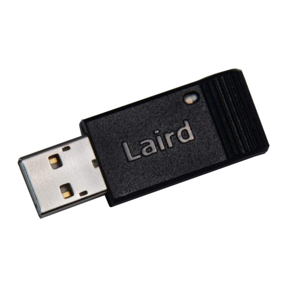
Page 6: Module Picture
BT800 Hardware Integration Guide Version 0.2 64 k EEPROM support for HID Proxy mode Bluetooth Controller subsystem FCC, IC, CE, and MIC approvals ODULE PICTURE CONN-GUIDE-BT800_v0_2 Americas: +1-800-492-2320 Option 2 Europe: +44-1628-858-940 Hong Kong: +852-2923-0610 www.lairdtech.com/bluetooth... -
Page 7: Block Diagram And Descriptions
BT800 Hardware Integration Guide Version 0.2 LOCK IAGRAM AND ESCRIPTIONS Figure 1: BT800 module block diagram Main Chip: CSR8510A10 BT800 is based on CSR8510A10 dual mode chip. The chip is a single-chip radio with on chip LDO regulators and baseband IC for Bluetooth 2.4 GHz systems including EDR to 3 Mbps. Dedicated signal and baseband processing is included for full Bluetooth operation. -
Page 8: Specifications
Miscellaneous Warranty 1 Year Bluetooth® Controller Subsystem Approved Approvals FCC / IC / CE / All BT800 series Note: Different DC power selections on BT800 are detailed in “ CONN-GUIDE-BT800_v0_2 Americas: +1-800-492-2320 Option 2 Europe: +44-1628-858-940 Hong Kong: +852-2923-0610 www.lairdtech.com/bluetooth... -
Page 9: Pin Definitions
BT800 Hardware Integration Guide Version 0.2 note Implementation .” IN DEFINITIONS Supply Pin Name Description Domain High switches SPI/PCM lines to SPI, Input with weak SPI_PCM#_SEL VDD_PADS Low switches SPI/PCM lines to internal pull-down PCM/PIO VDD_HOST Power supply (3.1V-3.6V) USB system positive supply Ground USB data plus with selectable USB+... - Page 10 BT800 Hardware Integration Guide Version 0.2 Supply Pin Name Description Domain This pin is reserved for future used. No connection. Ground PCM_SYNC/ Bidirectional, PCM synchronous data sync SPI SPI_CS#/ tri-state, with weak VDD_PADS chip select, active low internal pull-down Programmable input/output line PIO23 PCM synchronous data clock PCM_CLK/...
-
Page 11: Dc Electrical Characteristic
BT800 Hardware Integration Guide Version 0.2 7 DC E LECTRICAL HARACTERISTIC Table 1: Absolute maximum ratings Rating Unit Storage temperature ⁰C VREG_IN_USB -0.2 5.75 VREG_IN_HV -0.2 VDD_HOST -0.2 VDD_PADS -0.2 Other terminal voltages VSS - 0.4V VDD + 0.4 V Table 2: Recommended operating conditions Rating Unit... - Page 12 BT800 Hardware Integration Guide Version 0.2 (excluding load, Iload <100µA) Table 5: Digital I/O Characteristics Normal Operation Unit Input Voltage VIL input logic level low -0.4 0.7 x VDD + VIH input logic level high Output Voltage VOL output logic level low, IOL = 4.0mA VOH output logic level high, IOL = 0.75 x...
-
Page 13: Rf Characteristics
BT800 Hardware Integration Guide Version 0.2 8 RF C HARACTERISTICS Table 7: Receiver Characteristics RF Characteristics, VDD = 3.3V @ room BT. Spec. temperature unless otherwise specified Typ. Unit Maximum RF Transmit Power RF power variation over temperature range RF power variation over supply voltage range RF power variation over BT band RF power control range... -
Page 14: Interface
BT800 Hardware Integration Guide Version 0.2 NTERFACE PIO (Programmable I/O Ports) See the Device Terminal Functions section for the list of supplies to the PIOs. PIO lines are configured through software to have either weak or strong pull-ups or pull-downs. All PIO lines are configured as inputs with weak pull-downs at reset and have additional individual bus keeper configuration. -
Page 15: Pcm Interface
BT800 Hardware Integration Guide Version 0.2 Resume, detach and wake PIOs Battery charging from USB: dead battery provision, charge currents, charging in suspend modes and USB VBUS voltage consideration USB termination when interface is not in use ... - Page 16 BT800 Hardware Integration Guide Version 0.2 Figure 3: PCM Interface Slave 9.4.2 Long Frame Sync Figure 4: Long Frame Sync (Shown with 8-bit Companded Sample) Long Frame Sync is the name given to a clocking format that controls the transfer of PCM data words or samples.
-
Page 17: Gci Interface
BT800 Hardware Integration Guide Version 0.2 As with Long Frame Sync, BT800 samples PCM_IN on the falling edge of PCM_CLK and transmits PCM_OUT on the rising edge. PCM_OUT is configurable as high impedance on the falling edge of PCM_CLK in the LSB position or on the rising edge. 9.4.4 Multi-slot Operation More than 1 SCO connection over the PCM interface is supported using multiple slots. -
Page 18: Pcm Timing Information
BT800 Hardware Integration Guide Version 0.2 13-bit linear, 16-bit linear and 8-bit µ-law or A-law sample formats. A sample rate of 8ksps. Little or big endian bit order. For 16-bit slots, the 3 or 8 unused bits in each slot are filled with sign extension, padded with zeros ... - Page 19 BT800 Hardware Integration Guide Version 0.2 Delay time from 4MHz DDS generation dmclksy PCM_CLK high to 48MHz DDS generation 40.83 PCM_SYNC high dmclkpo Delay time from PCM_CLK high to valid PCM_OUT Delay time from 4MHz DDS generation dmclklsy PCM_CLK low to PCM_SYNC low (long 48MHz DDS generation 40.83...
-
Page 20: Pcm Slave Timing
BT800 Hardware Integration Guide Version 0.2 Figure 10: PCM Master Timing Short Frame Sync PCM Slave Timing Symbol Parameter Unit PCM clock frequency (Slave mode: sclk 2048 input) sclk PCM clock frequency (GCI mode) 4096 sclkl PCM_CLK low time sclkh PCM_CLK high time PCM Slave Mode Timing Parameters Symbol... - Page 21 BT800 Hardware Integration Guide Version 0.2 supinsclkl Set-up time for PCM_IN valid to CLK low hpinsclkl Hold time for PCM_CLK low to PCM_IN invalid Figure 11: PCM Slave Timing Long Frame Sync Figure 12: PCM Slave Timing Short Frame Sync CONN-GUIDE-BT800_v0_2 Americas: +1-800-492-2320 Option 2 Europe: +44-1628-858-940...
-
Page 22: Pcm_Clk And Pcm_Sync Generation
BT800 Hardware Integration Guide Version 0.2 9.10 PCM_CLK and PCM_SYNC Generation BT800 has 2 methods of generating PCM_CLK and PCM_SYNC in master mode: Generating these signals by DDS from BT800internal 4MHz clock. Using this mode limits PCM_CLK to 128, 256 or 512kHz and PCM_SYNC to 8kHz. Generating these signals by DDS from an internal 48MHz clock, which enables a greater range of ... - Page 23 BT800 Hardware Integration Guide Version 0.2 PCM_CLK Configure the digital audio interface using PSKEY_DIGITAL_AUDIO_CONFIG, see BlueCore Audio API Specification and the PS Key file. Figure 13: PCM Configuration The internal representation of audio samples within BT800is 16-bit and data on SD_OUT is limited to 16-bit per channel.
- Page 24 BT800 Hardware Integration Guide Version 0.2 SCK low to SD_OUT valid delay time SD_IN valid to SCK high set-up time SCK high to SD_IN invalid hold time Figure 14: Digital Audio Interface Slave Timing Table 14: Digital Audio Interface Master Timing Symbol Parameter Unit...
-
Page 25: Power Control And Regulation
BT800 Hardware Integration Guide Version 0.2 Figure 15: Digital Audio Interface Master Timing 10 P OWER ONTROL AND EGULATION See the Example Application Schematic for the regulator configuration. BT800 contains 5 regulators: USB linear regulator, to generate the 3.3 V for the USB interface and the input to the high-voltage ... -
Page 26: Low-Voltage Vdd_Dig Linear Regulator
BT800 Hardware Integration Guide Version 0.2 10.3 Low-voltage VDD_DIG Linear Regulator The integrated low-voltage VDD_DIG linear regulator is available to power a 0.90 V to 1.25 V supply rail which includes the digital circuits on CSR8510 WLCSP. The input voltage range is between 1.70 V and 1.95 V. -
Page 27: Antenna Performance
BT800 Hardware Integration Guide Version 0.2 11 A NTENNA PERFORMANCE The following diagrams illustrate antenna performance. Figure 16: BT800 Gain Table Figure 17: Network Analyzer output CONN-GUIDE-BT800_v0_2 Americas: +1-800-492-2320 Option 2 Europe: +44-1628-858-940 Hong Kong: +852-2923-0610 www.lairdtech.com/bluetooth... - Page 28 BT800 Hardware Integration Guide Version 0.2 CONN-GUIDE-BT800_v0_2 Americas: +1-800-492-2320 Option 2 Europe: +44-1628-858-940 Hong Kong: +852-2923-0610 www.lairdtech.com/bluetooth...
-
Page 29: Mechanical Dimensions And Land Pattern
BT800 Hardware Integration Guide Version 0.2 12 M ECHANICAL IMENSIONS AND ATTERN Note: Dimensions are in mm. CONN-GUIDE-BT800_v0_2 Americas: +1-800-492-2320 Option 2 Europe: +44-1628-858-940 Hong Kong: +852-2923-0610 www.lairdtech.com/bluetooth... -
Page 30: Implementation Note
BT800 Hardware Integration Guide Version 0.2 13 I MPLEMENTATION NOTE 13.1 PCB Layout on Host PCB Checklist (for PCB): MUST locate BT800/BT810 module close to the edge of PCB. Use solid GND plane on inner layer (for best EMC and RF performance). ... - Page 31 BT800 Hardware Integration Guide Version 0.2 13.1.2 USB dongle design example using BT800 Figure 19: USB Dongle Design Schematic 13.1.3 DC power supply options for using BT800 module Using USB bus power (5V+/-10%) Apply USB bus power (5V +/-10%) directly to the Pin-7 (VREG_IN_USB) and pull-high on Pin-8 (VREG_EN_RST#) to turn on the internal regulator.
-
Page 32: Application Note For Surface Mount Modules
PCB. Ultimately it is the responsibility of the customer to choose the appropriate solder paste and to ensure oven temperatures during reflow meet the requirements of the solder paste. Laird Technologies’ surface mount modules conform to J-STD-020D1 standards for reflow temperatures. - Page 33 BT800 Hardware Integration Guide Version 0.2 Figure 14-21: Recommended Reflow Temperature Temperatures should not exceed the minimums or maximums presented in Table Table 16: Recommended Maximum and minimum temperatures Specification Value Unit Temperature Inc./Dec. Rate (max) °C / Sec Temperature Decrease rate (goal) °C / Sec Soak Temp Increase rate (goal) .5 - 1...
-
Page 34: Fcc And Ic Regulatory
User’s Guide Requirements The BT800 complies with FCC Part 15 Rules for a Modular Approval. To leverage Laird’s grant, the conditions below must be met for the host device into which the BT800 is integrated: The antenna is installed with 20 cm maintained between the antenna and users. - Page 35 BT800 Hardware Integration Guide Version 0.2 provide information to the end user regarding how to install or remove this RF module in the user’s manual of the device into which the BT800 is integrated. The following FCC statements must be added in there entirety and without modification into a prominent place in the user’s guide for the device into which the BT800 is integrated: IMPORTANT NOTE: The product comply with the US/Canada portable RF exposure limit set forth...
- Page 36 BT800 Hardware Integration Guide Version 0.2 Radiation Exposure Statement: The product comply with the Canada portable RF exposure limit set forth for an uncontrolled environment and are safe for intended operation as described in this manual. The further RF exposure reduction can be achieved if the product can be kept as far as possible from the user body or set the device to lower output power if such function is available.
- Page 37 BT800 Hardware Integration Guide Version 0.2 This radio transmitter (Contains IC: 3147A-BT800) has been approved by Industry Canada to operate with the antenna types listed in table above with the maximum permissible gain and required antenna impedance for each antenna type indicated. Antenna types not included in this list, having a gain greater than the maximum gain indicated for that type, are strictly prohibited for use with this device.
-
Page 38: European Union Regulatory
Declaration: We, Laird, declare under our sole responsibility that the essential radio test suites have been carried out and that the above product to which this declaration relates is in conformity with all the applicable essential requirements of Article 3 of the EU Directive 1999/5/EC, when used for its intended purpose. -
Page 39: Ordering Information
BT800-ST BTv4.0 Dual Mode USB HCI Module – External Antenna variant 18.1 General Comments This is a preliminary datasheet. Please check with Laird for the latest information before commencing a design. If in doubt, ask. CONN-GUIDE-BT800_v0_2 Americas: +1-800-492-2320 Option 2... -
Page 40: Bluetooth Sig Approvals
The information contained in this manual and the accompanying software programs are copyrighted and all rights are reserved by Laird Technologies, Inc. Laird Technologies, Inc. reserves the right to make periodic modifications of this product without obligation to notify any person or entity of such revision. Copying, duplicating, selling, or otherwise distributing any part of this product or accompanying documentation/software without the prior consent of an authorized representative of Laird Technologies, Inc.
Need help?
Do you have a question about the BT800 series and is the answer not in the manual?
Questions and answers