Table of Contents
Advertisement
Quick Links
Advertisement
Table of Contents

Related Manuals for Laird BTM510


Summary of Contents for Laird BTM510
- Page 1 BTM510/511 MULTIMEDIA MODULE USER MANUAL Innovative Technology for a Connected World...
-
Page 2: Table Of Contents
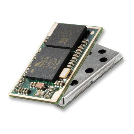
Module ..3 General Bluetooth Control ....22 ® ® Overview ..........3 Hardware Unit Control ....... 28 BTM510/511 Key Features ....3 Bluetooth Profiles ......30 ® Secure Simple Pairing ......37 Specifications ........4 Link Key Management ....... 37 Detailed Specifications ......4 Miscellaneous........ - Page 3 At only 14mm x 20mm, the compact size of the BTM510 makes it ideal for battery-powered or headset form factor audio and voice devices. With a 16-bit stereo codec and microphone inputs to support both stereo and mono applications, these modules also contain a full, integrated Bluetooth-qualified stack along with SPP, HFP 1.5, HSP, AVRCP, and A2DP...
- Page 4 2.402 – 2.480 GHz Channels 79 channels Frequency Hopping Adaptive Frequency Hopping Max Transmit Power +4 dBm @ antenna pad – BTM510 +4 dBmi from integrated antenna – BTM511 (provisional) Min Transmit Power -27 dBm @ antenna pad – BTM510 -27 dBmi from integrated antenna –...
- Page 5 1.7V – 3.6V DC Coexistence / Compatibility WLAN (802.11) 2-wire and 3-wire hardware coexistence schemes supported Connections External Antenna (option) Pad for 50 Ohm antenna – BTM510 Interface Surface Mount Pads Physical Dimensions 14.0mm x 20.0 x 1.6mm - BTM510 14.0mm x 26.0mm x 1.6mm - BTM511 (provisional)
- Page 6 Microphone, channel A+ (left) See note 4 MIC_AP_C Microphone, channel B- (right) See note 4 MIC_AN_C Microphone, channel B+ (right) See note 4 Unused Antenna connection – BTM510 (50 ohm matched) Unused Unused Unused Unused Unused Unused Unused Unused Unused...
-
Page 7: Module
BTM510/511 Bluetooth Multimedia Module ® SPECIFICATIONS Note: 1. Reset input is active low. Input is pulled up to VDD_IN via 22k. Minimum reset pulse width is 5ms. 2. LED drive pins are open drain outputs and hence the external circuit to the right should be used. -
Page 8: Operating Parameters
NOTES FOR PCB LAYOUT: The RF output pin must be matched to a 50Ω strip-line or coplanar waveguide on the antenna-less version (BTM510). Ensure that there are no exposed conductors under the module to avoid shorts to the test points on the module underside. -
Page 9: References
Just like telephony modems, Laird Technologies’ devices power up in an unconnected state and will only respond via the serial interface. In this state, the device will not even respond to Bluetooth inquiries. Then, just like controlling a modem, the host can issue AT commands which map to various Bluetooth activities. - Page 10 BTM510/511 Bluetooth Multimedia Module ® AT COMMAND SET gLOSSARY OF TERMS REFERENCE Description A2DP Advanced Audio Distribution Profile Asynchronous Connection-Oriented Link Analogue to Digital Converter AGHFP Audio Gateway Hands-Free Profile Command prefix, ‘Attention’ AVRCP Audio/Video Remote Control Profile BISM Bluetooth Intelligent Serial Module Class Of Device (also referred to as “device class”)
- Page 11 BTM410 / BTM411 Chipset CSR BC4-Ext Bluetooth version Features SSP, EIR, SCO (1), eSCO (1) Profiles (1) external codec required BTM510 / BTM511 Chipset CSR BC5MM-Ext Bluetooth version Features SSP, EIR, SCO, eSCO Profiles SPP, A2DP, AVRCP,HSP,HFP,DUN(DT) BTM520 / BTM521...
-
Page 12: Assumptions
BTM510/511 Bluetooth Multimedia Module ® AT COMMAND SET BTM - AT COMMAND SET REFERENCE This section describes the AT Command Set for a BTM module. This section is structured in functional groups of AT commands related to module configuration, Bluetooth profiles, hardware units and miscellaneous purposes. - Page 13 Figure 1 and Table 2 in “Bluetooth Assigned Numbers” [8]. Laird Technologies devices do not map to any predefined Major Service Class or Major Device Class and so the default devclass as shipped is 001F00, which means no Major Service Class and “Unclassified”...
- Page 14 Use AT+BTN? to read it back. An empty string (“”) will delete the string from non-volatile memory which will force the default name to be used which is “Laird BTM 789012”. The digits in the default friendly name represent the last six digits of the local Bluetooth address.
- Page 15 AT+BTX may put the device into the correct idle mode. 15. ATIn {Information} This will return the information about the Laird Technologies device and its status. Please refer to Table 4.2 (Appendix) for a complete list of supported ATIn parameters. For recognized values of n: Response: <cr,lf>As Appropriate<cr,lf>OK<cr,lf>...
- Page 16 BTM510/511 Bluetooth Multimedia Module ® AT COMMAND SET 3. ATSn=? {Read S Register – Valid Range} REFERENCE This will return the valid range of values for register n. For recognized values of n Response: <cr,lf>Sn:(nnnn..mmmm)<cr,lf>OK<cr,lf> For unrecognized values of n Response: <cr,lf>ERROR nn<cr,lf>...
- Page 17 BTM510/511 Bluetooth Multimedia Module ® AT COMMAND SET General S Registers REFERENCE Please refer to Appendix, Table 4.1 for a list of supported S Registers. The main purpose of S Registers is to make the device configuration persistent. All S Registers can be saved to non-volatile memory by AT&W.
- Page 18 BTM510/511 Bluetooth Multimedia Module ® AT COMMAND SET Inquiry Response Format REFERENCE The format of an inquiry result will be: <cr,lf><bd_addr>,<dev_class>,<friendly_name>,<rssi>,<eir_data><cr,lf> <bd_addr> = 12 digit, hexadecimal; <dev_class> = six digit, hexadecimal; <friendly_name> = printable ASCII character, enclosed by ‘ “ ‘...
- Page 19 BTM510/511 Bluetooth Multimedia Module ® AT COMMAND SET 6. AT+BTE=”<EIR-Data>” {Set Up Outgoing EIR Data} REFERENCE This command sets up outgoing EIR (extended inquiry response) data. Format: <EIR-Data> = printable ASCII character whenever possible, otherwise a two digit hexadecimal with preceding ‘\’ presenting one byte. Please note that the given data is written to baseband as it is (raw data) and no checks on the data format is performed.
- Page 20 BTM510/511 Bluetooth Multimedia Module ® AT COMMAND SET 2. IO-Capability (S321) REFERENCE S-Register 321 defines the IO-capability of the device. The setting is used for IO-capability negotiations prior to SSP in order to identify whether the IO-capabilities of both devices are sufficient for MITM protection (if required).
- Page 21 BTM510/511 Bluetooth Multimedia Module ® AT COMMAND SET 7. AT+BTW<bd_addr> {Initiate SSP} REFERENCE This command initiates secure simple pairing (dedicated bonding) with a device whose Bluetooth address is <bd_addr>. The correct term for this command’s action with respect to the Bluetooth specification 2.1+EDR [1] is “Dedicated Bonding”.
- Page 22 PASSKEY ? <BdAddr>,”<friendlyname>” Passkey request: Example: Expecting the user to enter the passkey displayed by the remote device. PASSKEY ? 0016A4000001,”Laird BTM 000001” Use AT+BTB<passkey>, example: AT+BTB012345 *see(1) below PAIR N <BdAddr>,”<friendlyname>”,<Passkey> Passkey notification: Display BdAddr, friendly name and passkey to Example: user.
- Page 23 BTM510/511 Bluetooth Multimedia Module ® AT COMMAND SET AT Commands for Legacy Pairing REFERENCE 1. AT+BTW<bd_addr> {Initiate Pairing} Provided the remote device is a Bluetooth 2.0 device or earlier and legacy pairing is not disabled (S323 = 0), this command is used to initiate legacy pairing with the device with <bd_addr>.
- Page 24 BTM510/511 Bluetooth Multimedia Module ® AT COMMAND SET AT Commands Managing Trusted Devices REFERENCE 1. AT+BTT? {List Trusted Device} This command is used to list the contents of the trusted device database. The link key is NOT displayed so the response is as shown below. If the list is empty then just the OK response is sent otherwise an OK is used to terminate the list.
- Page 25 BTM510/511 Bluetooth Multimedia Module ® AT COMMAND SET 1. ATX”<string>” {Send Data in Local Command and Connected Mode} REFERENCE This command is used to send data to the remote device when in local command and connected mode. The parameter <string> is any string not more than 29 characters long whereby a non-printable character (\hh, see below) counts three characters.
- Page 26 ATH command. Laird Technologies BTM devices provide a variety of ways of dropping a connection. One method is similar to the above, but instead a ^^^ character sequence is used. This is to eliminate ambiguity when a data call is in progress via a mobile phone which was established using the mobile phone’s Bluetooth...
- Page 27 BTM510/511 Bluetooth Multimedia Module ® AT COMMAND SET 8. SSO – S Registers REFERENCE The following table lists S registers for SSO profiles. Register Default Range Description 32..126 Escape sequence character. It is not ‘+’ by default as a Bluetooth serial link can be used to connect to a mobile phone which exposes an AT command set, which will in turn use ‘+’...
- Page 28 BTM510/511 Bluetooth Multimedia Module ® AT COMMAND SET 2. AT+BTG<bd_addr> {Make Device Selectively Connectable Only} REFERENCE Make the BTM device connectable for the device with the Bluetooth address <bd_addr> only. Connection requests from any other devices will be rejected. If the specified address is 000000000000 then incoming connections are accepted from any device, is as per AT+BTP without an address.
-
Page 29: Bluetooth Profiles
S register accordingly and issue AT&W followed by ATZ. 2.1 SPP Example This section gives an example on how an SPP connection between two Laird Technologies BTM devices can be established. It is assumed that two devices A and B are connected to a terminal program, e.g., Ezurio Terminal on a PC. - Page 30 BTM510/511 Bluetooth Multimedia Module ® AT COMMAND SET Phase Dev. AT Command Comment REFERENCE Initiate AT+SPD<BdAddr_DevB> Initiate SPP connection from device A to device B. connection Asynchronous messages: “PAIR 0…” (pairing successful, A and B) “RING…” (B only) “CONNECT…” (connected, A and B) Connected <data>...
- Page 31 BTM510/511 Bluetooth Multimedia Module ® AT COMMAND SET REFERENCE Figure 3.4: SPP example Device A - initiate connection, receiving data, command mode, disconnect Figure 3.5: SPP example Device B - incoming connection, receiving data, disconnection 2.2 ATA {Accept Incoming SPP Connection Request} Accept an incoming connection, which is indicated by the unsolicited string <cr,lf>RING...
- Page 32 Response: <cr,lf>NO CARRIER<cr,lf> 2.7 SPP – Incoming Connections The Laird Technologies BTM device can be configured using the AT+BTP or AT+BTG command so that it will scan for incoming connections from other Bluetooth devices. It can also be configured via S Register 512 to be in this mode by default on power up.
- Page 33 BTM510/511 Bluetooth Multimedia Module ® AT COMMAND SET 2.9 SPP – S Registers REFERENCE S Registers for SPP are summarized in Table 3.10. Register Default Range Description -1..15 Number of RING indication before automatically answering an incoming connection. A value of 0 disables autoanswer.
- Page 34 3.1 A2DP Example 1 REFERENCE This section gives an example of an A2DP connection between a Laird Technologies BTM device as Audio Sink (wireless speaker/ wireless headphones) and a PC with a built in Bluetooth device and Toshiba Bluetooth Stack 2.1 as Audio Source.
- Page 35 BTM510/511 Bluetooth Multimedia Module ® AT COMMAND SET REFERENCE Figure 3.6: A2DP example 1 – PC Bluetooth settings Figure 3.7: A2DP example 1 – Start discovery of Bluetooth devices 35 www.lairdtech.com Laird Technologies...
- Page 36 AT COMMAND SET REFERENCE Figure 3.8: A2DP example 1 – Select Bluetooth device (Click “Refresh” if Laird BTMM is not listed) Figure 3.9: A2DP example 1 – Confirm pairing (here: Secure Simple Pairing, no PIN required) Figure 3.10: A2DP example 1: Connection established 36 www.lairdtech.com...
- Page 37 Figure 3.11: A2DP example 1: New Bluetooth Audio Device in the Device Manager 3.2 A2DP Example 2 This section gives an example of an A2DP connection between a Laird Technologies BTM5xx device (A) as Audio Sink (wireless speaker/ wireless headphones) and another Laird Technologies BTM5xx device (B) as Audio source.
- Page 38 BTM510/511 Bluetooth Multimedia Module ® AT COMMAND SET Phase Dev. AT Command Comment REFERENCE Preparation AT&F* Restore factory default settings A2DP profile is enabled per default in S102 ATS300=2 Enable Audio Source role ATS515=$080400 Set A2DP device class (source) AT&W...
- Page 39 BTM510/511 Bluetooth Multimedia Module ® AT COMMAND SET REFERENCE Figure 3.14: A2DP Example 2 –Initiate and Release Connection from Device B (Source) Figure 3.15: A2DP Example 2 – Accepting Connection and Volume Adjustment Device A (Sink) 3.3 Enable A2DP The advanced audio distribution profile (A2DP) is enabled by issuing ATS102=128. After verifying that a role has been set (S300 != 0) the S registers must be saved by AT&W.
- Page 40 BTM510/511 Bluetooth Multimedia Module ® AT COMMAND SET 4. Set A2DP Device Class REFERENCE ATS515=$<device_class >; AT&W; ATZ For compliance with the A2DP specification, [2] (and hence for successful interoperability to other devices) it is required to set up a valid device class code. The default device class code of a BTM device is 0x001F00 which is invalid for the A2DP profile.
- Page 41 BTM510/511 Bluetooth Multimedia Module ® AT COMMAND SET 4.2 Output Gain Settings – A2DP Sink REFERENCE AT+GOU / AT+GOD AT+GOU – Increment audio output gain (volume). AT+GOD – Decrement audio output gain (volume). Response: <cr><lf>OK<cr><lf> <cr><lf>ERROR 57<cr><lf> – Maximum gain level reached <cr><lf>ERROR 58<cr><lf>...
- Page 42 BTM510/511 Bluetooth Multimedia Module ® AT COMMAND SET Task AT-Command / SRegister Comment REFERENCE Initiate outgoing A2DP con- AT+APD<bd_addr> Response if accepted: nection “CONNECT 0123456789012,110D,>” Response if rejected: “NO CARRIER 110D” Close only A2DP connection “AT+APH” or Response: “ATH110D” “NO CARRIER 110D” if connection has existed and S329=0 “NO CARRIER”...
- Page 43 Table 3.17: AVRCP Supported Features on BTM5xx 5.1 AVRCP Example 1 This section gives an example of an AVRCP connection between a Laird Technologies BTM5xx device as AVRCP Controller and a PC with a built in Bluetooth device and Toshiba Bluetooth Stack 2.1 as AVRCP Target.
- Page 44 BTM510/511 Bluetooth Multimedia Module ® AT COMMAND SET Phase Dev. AT Command Comment REFERENCE Preparation BTM5xx AT&F* Restore factory default settings AVRCP profile is enabled per default in S102 AVRCP Control role is enabled per default in S301 Reset Preparation 1.) Select “Options…”...
- Page 45 BTM510/511 Bluetooth Multimedia Module ® AT COMMAND SET REFERENCE Figure 3.16: AVRCP Example 1 – Bluetooth Address of PC and AV Remote Control Service Figure 3.17: AVRCP Example 1 – Player Selection and Receiving Commands Display Setup 45 www.lairdtech.com Laird Technologies...
- Page 46 BTM510/511 Bluetooth Multimedia Module ® AT COMMAND SET REFERENCE Figure 3.18: AVRCP Example 1 – Secure simple pairing dialogue Figure 3.19: AVRCP Example 1 – BTM5xx Preparation and Connection Setup Figure 3.20: AVRCP Example 1 – BTM5xx Sending Commands and Connection Release Figure 3.21: AVRCP Example 1 –...
- Page 47 BTM510/511 Bluetooth Multimedia Module ® AT COMMAND SET 5.2 AVRCP - Control (CT) and Target (TG) REFERENCE This section describes AT Commands an S registers which are common to BTM5xx AVRCP Controller role and AVRCP Target role. 5.2.1 Initiate AVRCP Connection AT+AVD<bd_addr...
- Page 48 BTM510/511 Bluetooth Multimedia Module ® AT COMMAND SET 5.3.3 Send Remote Control Command REFERENCE AT+AVC<operation_id >,<button_state> Send a remote control command to a connected AVRCP target. Internally, a PASS THROUGH command is created and sent to the PANEL subunit of the AVRCP target.
- Page 49 BTM510/511 Bluetooth Multimedia Module ® AT COMMAND SET 5.4.4 PASS THROUGH Indication REFERENCE An incoming PASS THROUGH command will be indicated by an unsolicited message. AVPTI <subunit_id >,<operation_id >,<button_state> For subunit_id see Table 3.21. For operation_id see Table 3.20. <button_state>: ‘0’ is Button pushed ‘1’...
- Page 50 BTM510/511 Bluetooth Multimedia Module ® AT COMMAND SET Task AT-Command / S Register Comment REFERENCE Send a Unit Info request AT+AVU Response on command completion: “AVUR (Control) <n>,<unit_id >,<unit_type >,<company_ >” Successful if <n> = 0 Send a Subunit Info request...
- Page 51 BTM510/511 Bluetooth Multimedia Module ® AT COMMAND SET Command Operation ID REFERENCE Select 0x00 0x01 Down 0x02 Left 0x03 Right 0x04 Right up 0x05 Right down 0x06 Left up 0x07 Left down 0x08 Root menu 0x09 Setup menu 0x0A Contents menu...
- Page 52 BTM510/511 Bluetooth Multimedia Module ® AT COMMAND SET Unit / Subunit Type Value REFERENCE Monitor 0x00 Audio 0x01 Printer 0x02 Disc 0x03 Tape recorder player 0x04 Tuner 0x05 0x06 Camera 0x07 Reserved 0x08 Panel 0x09 Bulletin board 0x0A Camera storage...
- Page 53 BTM510/511 Bluetooth Multimedia Module ® AT COMMAND SET Message Comment REFERENCE AVSR <n>,<page >,<pagedata > Response to AT+AVS (SUBUNIT INFO Request), Indi- cates completion of command <n> = status 0 – success 1 – fail 4 – timeout <page > : requested page [0..31] <pagedata...
- Page 54 BTM510/511 Bluetooth Multimedia Module ® AT COMMAND SET HSP Feature Support in HS Support in AG REFERENCE Specification BTM5xx Specification BTM5xx 1. Incoming audio connection 2. Outgoing audio connection 3. Audio connection transfer 4. Remote audio volume control M: mandatory...
- Page 55 BTM510/511 Bluetooth Multimedia Module ® AT COMMAND SET Connection status Outcome of AT+HSB (“AT+CKPD=200”) REFERENCE ACL connected (ATI63=1) Audio link will be initiated by AG Referred to as “Audio Connection Transfer from AG to HS” in HSPv1.2 Audio connected (ATI63=2)
- Page 56 BTM510/511 Bluetooth Multimedia Module ® AT COMMAND SET 6.1.6 Headset summary REFERENCE Task AT-Command / S Register Comment Enable HSP-HS role S102 0x02 = HS role of HSP (bitmask), needs subsequent “AT&W” and “atz” to activate Initiate ACL from headset AT+HSD<bd_addr...
- Page 57 BTM510/511 Bluetooth Multimedia Module ® AT COMMAND SET 6.2.1 Initiate ACL Connection from AG (HSP) REFERENCE AT+HSGD<bd_addr > Initiate ACL connection from local headset-gateway instance to remote device with <bd_addr >. The remote device must support the headset role (HS) of the headset profile (HSP).
- Page 58 BTM510/511 Bluetooth Multimedia Module ® AT COMMAND SET 6.2.7 Enable Automatic Alerting on SLC Establishment REFERENCE S345 S-Register 345 enables automatic alerting on ACL establishment. It contains a bitmask where bit0 corresponds to outgoing ACL connections and bit1 corresponds to incoming ACL connections.
- Page 59 BTM510/511 Bluetooth Multimedia Module ® AT COMMAND SET 6.2.12 AG - HSP Summary (HSG) REFERENCE Task AT-Command / Comment S Register Enable HSP-AG role S102 0x08 = AG role of HSP (bitmask), needs subsequent “AT&W” and “atz” to activate Initiate SLC from AG (HSP) AT+HSGD<bd_ad-...
- Page 60 BTM510/511 Bluetooth Multimedia Module ® AT COMMAND SET 7. HFP (Hands-Free Profile) REFERENCE The Hands-free profile (HFP) defines how two devices supporting HFP shall interact with each other on a point-to-point basis. The use case for HFP is a hands-free unit that is connected wirelessly to an audio gateway.
- Page 61 BTM510/511 Bluetooth Multimedia Module ® AT COMMAND SET 7.1 Hands-Free Unit Role (HF) REFERENCE Hands-free role is activated by setting flag 0x10 in S102 plus “AT&W” plus “atz“. Figure 3.24 outlines a block diagram with a BTM5xx in hosted operation mode.
- Page 62 BTM510/511 Bluetooth Multimedia Module ® AT COMMAND SET 7.1.5 Answer Incoming Call from HF (#4_4.13) REFERENCE AT+HFCA Answer an incoming call. “ATA” will be sent to the AG. In return, the audio gateway shall update its “+CIEV” indicators (“call=1” and “callsetup=0”) and send appropriate messages to the HF.
- Page 63 BTM510/511 Bluetooth Multimedia Module ® AT COMMAND SET 7.1.12 Query Subscriber Number from HFG (#20_4.30) REFERENCE AT+HFS? Query subscriber numbers from HFG. “AT+CNUM” is sent to the HFG. HFG will send the subscriber number information, indicated on the HF by HF”+CNUM,,,””. An “OK” will be sent by HFG on termination, indicated on HF by the asynchronous message HF”CNUM,OK”.
- Page 64 BTM510/511 Bluetooth Multimedia Module ® AT COMMAND SET 7.1.15 “+CIEV” Indicators Received from AG (#2) REFERENCE HFI”<indicator_string>”,<val> (S333=1, default) HFI<indicator_id>,<val> (S333=0) Inform the HF-host about a “+CIEV” indicator message received from the connected audio gateway. S-Register 333 enables verbose mode for HFI indicators. Possible indicators are listed in Table 3.29.
- Page 65 BTM510/511 Bluetooth Multimedia Module ® AT COMMAND SET HF”CLIP,ERROR” REFERENCE HFG has replied with ERROR to reception of “AT+CLIP<…>”. HF”+CLIP,n,m,1234567” A “calling line identification notification” (+CLIP:”1234567”,<type>) has been received from the HFG. This message is sent by the HFG on incoming calls together with HF”RING”.
- Page 66 BTM510/511 Bluetooth Multimedia Module ® AT COMMAND SET HF”CMEE,OK” REFERENCE HFG has replied with OK to reception of “AT+CMEE=1”. HF”CMEE,ERROR” HFG has replied with “ERROR” to reception of “AT+CMEE=1”. HFI<…> Indicator (+CIEV…) from audio gateway was received. Refer to section 7.1.15 on page 64.
- Page 67 BTM510/511 Bluetooth Multimedia Module ® AT COMMAND SET 7.2 Audio Gateway Role (AG-HFP / HFG) REFERENCE Audio gateway role is activated by setting flag 0x40 in S102 plus “AT&W” plus “atz“. Please refer to Figure 3.23 (page 56) for a block diagram of an audio gateway with a BTM5xx in hosted operation mode.
- Page 68 BTM510/511 Bluetooth Multimedia Module ® AT COMMAND SET 7.2.5 Signal Incoming Call from AG to HF (#4_4.13) REFERENCE AT+HFGC”<number_string>”,<type > Signal an incoming call by sending “RING” and “+CLIP:”<number_string>”,<type >” to HF periodically. The <number_string> field represents the phone number of the ringing party.
- Page 69 BTM510/511 Bluetooth Multimedia Module ® AT COMMAND SET Indicator name indicator_id Range of value Section in HFP spec. [5] REFERENCE Service 0..1 Call 0..1 All call related sections Call setup 0..3 Call held 0..2 Signal 0..5 Roam 0..1 Battery Charge 0..5...
- Page 70 BTM510/511 Bluetooth Multimedia Module ® AT COMMAND SET Response: REFERENCE <cr><lf>OK<cr><lf> command valid, record added <cr><lf>ERROR 05<cr><lf> syntax or value range error <cr><lf>ERROR 67<cr><lf> maximum number of subscriber number records reached AT+HFGS? This command returns a list of currently available subscriber number records which would be sent to the HF-unit on request (“AT+CNUM”...
- Page 71 BTM510/511 Bluetooth Multimedia Module ® AT COMMAND SET HFG”VGS<n>” REFERENCE Speaker gain setting message was received from HF (“+VGS:<n>”) with n = gain [0..15]. HFG”VGM<n>” Microphone gain setting message was received from HF (“+VGM:<n>”) with n = gain [0..15]. HFG”AU1”...
- Page 72 BTM510/511 Bluetooth Multimedia Module ® AT COMMAND SET 7.2.13 AG - HFP summary (HFG) REFERENCE Task AT-Command / S Register Comment Enable HFP-AG role S102 0x40 = AG role of HFP (bitmask), needs subsequent “AT&W” and “ATZ” to activate Initiate SLC from HFG AT+HFGD<bd_addr...
- Page 73 BTM510/511 Bluetooth Multimedia Module ® AT COMMAND SET 8. DUN (Dial-Up Networking Profile) REFERENCE The Dial-up networking profile (DUN,[6]) defines protocols and procedures for the dial-up networking use case. Scenarios are the usage of a wireless modem or a cellular phone for dial–up Internet connections or the usage of a wireless modem or cellular phone to receive data calls by a PC.
- Page 74 Table 3.33: DUN – Summary of S Registers and AT Commands Hardware Units (BTM510 / 511) This section covers S-Registers and AT-Commands that are related to hardware units of a BTM510 or BTM511 device. For this section, please also refer to the bluecore data sheet [10] for more detailed information.
- Page 75 BTM510/511 Bluetooth Multimedia Module ® AT COMMAND SET 2. Codec Gain REFERENCE Analogue input and output gains (Input Amplifier, Output Amplifier, Figure 3.25) can be set to one of 23 steps called “Gain Level”. To each gain level, an overall gain (dBr) is assigned, according to Table 3.34.
- Page 76 BTM510/511 Bluetooth Multimedia Module ® AT COMMAND SET Output Gain Level or Overall Gain (dBr) Digital Analogue REFERENCE Input Gain Level S689 or S690 Component Component S589 or S590 -18.0 -21.0 -23.5 -27.0 -29.5 -33.0 -35.5 -39.0 -41.5 -45.0 Table 3.40: Gain Table...
- Page 77 BTM510/511 Bluetooth Multimedia Module ® AT COMMAND SET 3. Mic Input Gain REFERENCE A microphone preamplifier which adds extra 24dB to input gain, is controlled by S-Register 415. The microphone amplifier is enabled by ATS415=1 and disabled by ATS415=0. Refer to Table 3.43.
- Page 78 BTM510/511 Bluetooth Multimedia Module ® AT COMMAND SET Register Default Range Description REFERENCE S415 0..1 Enable Microphone Input Gain, adds extra 24dB to input gain S419 0..6 Set sampling rate for Audio Loopback: 0 = 8 kHz 1 = 11.025 kHz 2 = 16 kHz 3 = 22.050 kHz...
- Page 79 BTM510/511 Bluetooth Multimedia Module ® AT COMMAND SET GPIO Pin Alternative Function REFERENCE (BTM510/511) Handshaking Wi-Fi Coexistence GPIO1 BT_Active (1) GPIO2 GPIO3 GPIO4 GPIO5 BT_State/BT_Priority GPIO6 Wlan_Active GPIO7 Rf_Active GPIO8 (1) BT_Active = RxEnable OR TxEnable GPIO - Alternative Functions...
- Page 80 BTM510/511 Bluetooth Multimedia Module ® AT COMMAND SET Register GPIO Default Range Comment REFERENCE S650 0..1 Mode for GPIO Config Registers: 0 = no mask; 1 = enable i/o pin state mask S651 GPIO1 0x0000 0..0xFFFF GPIO Configuration Registers S650 must be set to 0 to enable configu-...
- Page 81 BTM510/511 Bluetooth Multimedia Module ® AT COMMAND SET Miscellaneous REFERENCE 1. SCO / eSCO Audio Link BTM modules provide an AT command to establish an SCO/eSCO audio connection between a pair of BTM modules (or BISM2). This enables the user to create bidirectional audio links independently from a particular Bluetooth profile.
-
Page 82: Link Key Management
BTM510/511 Bluetooth Multimedia Module ® AT COMMAND SET 1.1 SCO / eSCO Asynchronous Messages REFERENCE The following asynchronous messages apply to SCO/eSCO connections. AUDIO ON (SCO) This response is sent to the host when a SCO channel has been established. - Page 83 BTM510/511 Bluetooth Multimedia Module ® AT COMMAND SET Task AT-Command Comment REFERENCE Get connection status ATI60 0 = not connected of SPP 1 = connected (local command mode) 2 = connected (remote command mode) identical with ATI9 Get connection status of...
- Page 84 BTM510/511 Bluetooth Multimedia Module ® AT COMMAND SET 5. Legacy Response Format (BISM2) REFERENCE Some BISM2 responses have been slightly changed on BTM modules in order to provide enhanced functionality. If required, a BISM2 compatible response format can be enabled by S Register 329.
- Page 85 BTM510/511 Bluetooth Multimedia Module ® AT COMMAND SET 6. UUIDs in “CONNECT”/”NO CARRIER” Messages REFERENCE In profiles where functionality and command set differs between both possible roles (asynchronous profiles), role indicating UUIDs are used in the “CONNECT” and “NO CARRIER” messages. HSP and HFP are asynchronous profiles.
- Page 86 BTM510/511 Bluetooth Multimedia Module ® AT COMMAND SET REFERENCE Figure 3.33: Page and Inquiry Scan Intervals and Windows 8. Sniff Mode Bluetooth connections are master/slave in nature. A master sends packets and a slave has to acknowledge that packet in the next timeslot. Timeslots in Bluetooth are 625 microseconds wide.
- Page 87 BTM510/511 Bluetooth Multimedia Module ® AT COMMAND SET 9. Maximum RF-Tx Power Level REFERENCE The maximum RF transmit power level for all operation states (inquiring/connecting/in connection) is controlled by S541/S542. 10. Manufacturing Info String A string with manufacturing information can be retrieved by “ATI200”.
- Page 88 BTM510/511 Bluetooth Multimedia Module ® AT COMMAND SET REFERENCE Figure 3.35: BREAK capability in Ezurio Terminal 16. Append Bluetooth Address to Friendly Name If S Reg 593 is set to 1, then the last six hex digits of the Bluetooth address are automatically appended to the friendly name.
-
Page 89: Appendix
BTM510/511 Bluetooth Multimedia Module ® AT COMMAND SET Appendix REFERENCE General S Registers The following table lists all general S Registers. Please not that this is not a complete listing of S Registers. Additional S registers, associated with a certain profile or feature are described in the appropriate section above. - Page 90 BTM510/511 Bluetooth Multimedia Module ® AT COMMAND SET Register Deflt. Range Description REFERENCE S334 0..1 Enable Extended Sdp Error Codes 0 - disable 1 – enable S504 0..1 Enable silent operation: Setting to 1 will force S0 to -1 and will suppress messages arising from connections or pairing.
- Page 91 BTM510/511 Bluetooth Multimedia Module ® AT COMMAND SET Register Deflt. Range Description REFERENCE S512 0..7 Specify power up state. When set to 0, AT+BTO is required to open the device for Bluetooth activity. When set to 1, it proceeds to a state as if AT+BTO was entered.
- Page 92 BTM510/511 Bluetooth Multimedia Module ® AT COMMAND SET Register Deflt. Range Description REFERENCE S520 9600 1200.. Change to a standard baud rate. The effect is immediate and in ..115200 fact the OK will be sent at the new baud rate. Only one of the following baud rates are accepted: 1200,2400,4800,9600,19200, 28800,38400,57600,115200.
- Page 93 BTM510/511 Bluetooth Multimedia Module ® AT COMMAND SET Register Deflt. Range Description REFERENCE S531 0..4 Specifies the mode on connection establishment. 0 = Normal, that data is exchanged between UART and RF. 1 = LOCAL_COMMAND. UART input is parsed by the AT interpreter and RF data is discarded.
- Page 94 BTM510/511 Bluetooth Multimedia Module ® AT COMMAND SET Register Deflt. Range Description REFERENCE S552 $0122 $0..$fff This register specifies in each 4 bit nibble, how the DTR, DCD, RI output pins are controlled when in a Bluetooth connection Nibble 0..3 specifies the source for DTR 4..7 specifies the source for DCD...
- Page 95 BTM510/511 Bluetooth Multimedia Module ® AT COMMAND SET Register Deflt. Range Description REFERENCE S560 15..120 Disconnect timeout in seconds. This timer specifies how long to wait for confirmation from the peer device and/or the underlying stack that the connection has been successfully torn down. There can be instances where a confirmation does not arrive and so in this case this timer is used to ‘close off’...
- Page 96 BTM510/511 Bluetooth Multimedia Module ® AT COMMAND SET ATI Commands REFERENCE The following table lists all ATIn parameters supported by a BTM device. ATI commands provide general infor- mation about the BTM device and status information. Commands Information ATI0 The product name/variant.
- Page 97 BTM510/511 Bluetooth Multimedia Module ® AT COMMAND SET Commands Information REFERENCE ATI42 State information. Where the response values are as follows: 13 = NotOpen 14 = OpenIdle 15 = Ringing 16 = OnlineCommand 172 to 177 = waiting for connectable and/or discoverable where the lowest significant digit equates to the value stored in S Register 512 or 555.
- Page 98 BTM510/511 Bluetooth Multimedia Module ® AT COMMAND SET Error Responses REFERENCE Error Description Register not recognized Value for register is out of range Incoming call NOT pending No call to connect to. This error code has meaning for ATO only...
- Page 99 BTM510/511 Bluetooth Multimedia Module ® AT COMMAND SET Error Description REFERENCE Unknown Audio Gateway Command Busy, try later Command or operation not allowed No A2DP role has been set (see S register 300) No AVRCP role has been set (see S register 301)
- Page 100 BTM510/511 Bluetooth Multimedia Module ® AT COMMAND SET References REFERENCE “Bluetooth Specification Version 2.1 + EDR [vol3]”, 26 July 2007 http://www.bluetooth.com/Bluetooth/Technology/Building/Specifications/ (click on “Core Specification v2.1 + EDR”) “Advanced Audio Distribution Profile Specification” Rev. V12, 16/04/2007 http://www.bluetooth.com/Bluetooth/Technology/Works/A2DP.htm (link at bottom of page “Need more? View the Advanced Audio Distribution Profile (A2DP) 1.2”) “Audio/Video Remote Control Profile”...
- Page 101 20cm to the human body, whereas portable devices can be used closer that 20cm to the body. In the case where the BTM510 module is used in a portable device, additional SAR testing must be performed on the complete product.
- Page 102 Article 3 of the EU Directive 1995/5/EC, when used for its intended purpose. Place of Issue: Ezurio Ltd dba Laird Technologies Saturn House, Mercury Park Wooburn Green HP100HH,...
- Page 103 Article 3 of the EU Directive 1995/5/EC, when used for its intended purpose. Place of Issue: Ezurio Ltd dba Laird Technologies Saturn House, Mercury Park Wooburn Green HP100HH,...
-
Page 104: Mechanical Drawings
BTM510/511 Bluetooth Multimedia Module ® MEChANICAL DRAWINgS BTM510 Mechanical Diagrams 104 www.lairdtech.com Laird Technologies... - Page 105 BTM510/511 Bluetooth Multimedia Module ® MEChANICAL DRAWINgS BTM510 Mechanical Diagrams 105 www.lairdtech.com Laird Technologies...
- Page 106 BTM510/511 Bluetooth Multimedia Module ® MEChANICAL DRAWINgS BTM511 Mechanical Diagrams 106 www.lairdtech.com Laird Technologies...
- Page 107 BTM510/511 Bluetooth Multimedia Module ® MEChANICAL DRAWINgS BTM511 Mechanical Diagrams 107 www.lairdtech.com Laird Technologies...
- Page 108 BTM510/511 Bluetooth Multimedia Module ® MEChANICAL DRAWINgS BTM511 Mechanical Diagrams 108 www.lairdtech.com Laird Technologies...
- Page 109 BTM510/511 Bluetooth Multimedia Module ® MEChANICAL DRAWINgS BTM510 Development Kit Schematic 109 www.lairdtech.com Laird Technologies...
- Page 110 BTM510/511 Bluetooth Multimedia Module ® MEChANICAL DRAWINgS BTM510 Development Kit Schematic 110 www.lairdtech.com Laird Technologies...
- Page 111 BTM510/511 Bluetooth Multimedia Module ® MEChANICAL DRAWINgS BTM510 Development Kit Schematic 111 www.lairdtech.com Laird Technologies...
- Page 112 BTM510/511 Bluetooth Multimedia Module ® MEChANICAL DRAWINgS BTM511 Development Kit Schematic 112 www.lairdtech.com Laird Technologies...
- Page 113 BTM510/511 Bluetooth Multimedia Module ® MEChANICAL DRAWINgS BTM511 Development Kit Schematic 113 www.lairdtech.com Laird Technologies...
- Page 114 BTM510/511 Bluetooth Multimedia Module ® MEChANICAL DRAWINgS BTM511 Development Kit Schematic 114 www.lairdtech.com Laird Technologies...
-
Page 115: Ordering Information
Development Board with BTM511 soldered in place Q2-2009 gENERAL COMMENTS This is a preliminary datasheet. Please check with Laird Technologies for the latest information before commencing a design. If in doubt, ask. Refer to the schematic BTV-R-003.pdf for the Development Kit on the following two pages for examples of typical pin connections. - Page 116 As a result of any event, circumstance, action, or abuse beyond the control of Laird Technologies, whether such damages be direct, indirect, consequential, special or otherwise and whether such damages are incurred by the person to whom this warranty extends or third party. If, after inspection, Laird Technologies’ determines that there is a defect, Laird Technologies will repair or replace the OEM transceiver at their discretion. If...
Need help?
Do you have a question about the BTM510 and is the answer not in the manual?
Questions and answers