Laird BTM410 User Manual
Data module
Hide thumbs
Also See for BTM410:
- User manual (45 pages) ,
- Hardware integration manual (26 pages) ,
- Quick start manual (6 pages)
Table of Contents
Advertisement
Quick Links
Advertisement
Table of Contents

Related Manuals for Laird BTM410


Summary of Contents for Laird BTM410
- Page 1 Version 3.0...
- Page 2 BTM410/411 ® Bluetooth AT Data Module REVISION HISTORY EVISION ISTORY Revision Description Version 1.0 03/01/2012 – Initial Release Version 2.0 12/03/2012 – General updates and compliant with firmware v16.1.3.0 Version 3.0 04/13/2012 – Reformatting and general edits www.lairdtech.com Laird Technologies...
-
Page 3: Table Of Contents
List of UUIDs ................... 61 References....................62 FCC Regulatory Statements ..............63 BTM410 FCC and Industry Canada Statements ........63 BTM411 FCC and Industry Canada Statements ........64 Declarations of Compliance ..............65 EU Declaration of Conformity – BTM410 ..........65 EU Declaration of Conformity –... -
Page 4: Overview And Key Features
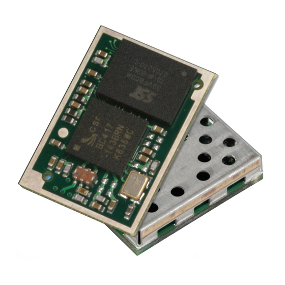
EATURES AND KEY FEATURES The BTM410 and BTM411 Bluetooth® modules from Laird Technologies have been designed to meet the needs of developers who wish to add robust, short range Bluetooth data connectivity to their products. They are based on the market leading Cambridge Silicon Radio BC04 chipset, providing exceptionally low power consumption with outstanding range. -
Page 5: Specifications
Channels 79 channels Frequency Hopping Adaptive Frequency Hopping Max Transmit Power +4 dBm at antenna pad – BTM410 +4 dBmi from integrated antenna – BTM411 Min Transmit Power -27 dBm at antenna pad – BTM410 -27 dBmi from integrated antenna – BTM411... -
Page 6: Pin Definitions
Connections Interface Surface Mount Pads External Antenna Pad for 50 Ohm antenna (BTM410) Physical Dimensions 12.5mm x 18.0 x 3.4mm BTM410 12.5mm x 22.0mm x 3.4mm BTM411 Weight 3 grams Environmental Operating Temperature -40°C to +85°C Storage Temperature -40°C to +85°C... - Page 7 2. Reset input is active low. Input is pulled up to VDD_IN via 22k. Minimum reset pulse width is 5ms. 3. Pins 8 – 11 (SPI related) are only for Laird internal production purposes. 4. Pins 25-37 should be left not connected on modules with integrated antenna.
-
Page 8: Operating Parameters
BTM410/411 ® Bluetooth AT Data Module OPERATING Operating Parameters PARAMETERS Table 2-3: Operating parameters Recommended Operating Conditions OPERATING CONDITION VDD_USB (USB compatibility not required) VDD_USB (USB compatibility required) VDD_IO VDD_IN Voltage Specifications Table 2-4: Voltage specifications (VUSB) Logic Levels (VUSB) INPUT VOLTAGE LEVELS 0.7VDD_USB... -
Page 9: At Command Set Reference
Just like telephony modems, Laird Technologies’ devices power up in an unconnected state and will only respond via the serial interface. In this state the device will not even respond to Bluetooth Inquiries. -
Page 10: Glossary Of Terms
BTM410/411 ® Bluetooth AT Data Module Glossary of Terms AT COMMAND SET REFERENCE Table 3-2: Glossary of Terms Description A2DP Advanced Audio Distribution Profile Asynchronous Connection-Oriented Link Analogue to Digital Converter AGHFP Audio Gateway Hands-Free Profile Command prefix, ‘Attention’ AVRCP... -
Page 11: Overview Of The Btm Product Family
® Bluetooth AT Data Module Overview of the BTM Product Family AT COMMAND SET REFERENCE Table 3-3: BTM 410 and 411 products BTM410 / BTM411 Chipset CSR BC4-Ext Bluetooth version Features SSP, EIR, SCO (1), eSCO (1) Profiles (1) external codec required... -
Page 12: Btm - At Command Set
BTM410/411 ® Bluetooth AT Data Module AT COMMAND SET BTM - AT Command Set REFERENCE This section describes the AT Command Set for a BTM module. This section is structured in functional groups of AT commands, related to module configuration, Bluetooth profiles, hardware units and miscellaneous purposes. -
Page 13: General At Commands
BTM410/411 ® Bluetooth AT Data Module General AT Commands AT COMMAND SET REFERENCE 1. AT This command is used to check whether or not the module is available. Response: <cr,lf>OK<cr,lf> 2. ATEn {Enable/Disable Echo} This command enables or disables the echo of characters to the screen. A valid parameter value will be written to S Register 506. - Page 14 AT Data Module AT COMMAND SET AT COMMAND SET Laird Technologies devices do not map to any predefined Major Service Class or Major Device Class REFERENCE REFERENCE and so the default devclass as shipped is 001F00, which means no Major Service Class and “Unclassified”...
- Page 15 BTM410/411 ® Bluetooth AT Data Module AT COMMAND SET 9. AT+BTN? {Read Friendly Name from Non-volatile Memory} REFERENCE Read the default friendly name from non-volatile memory. Response: <cr,lf>”My Friendly Name”<cr,lf> <cr,lf>OK<cr,lf> 10. AT+BTF<bd_addr> {Get Remote Friendly Name} This command gets the remote friendly name of the peer specified.
-
Page 16: At Commands For S Registers
AT+BTX may put the device into the correct idle mode. 15. ATIn {Information} This will return the information about the Laird Technologies device and its status. Please refer to Table 37 (Appendix Table 4-2) for a complete list of supported ATIn parameters. - Page 17 BTM410/411 ® Bluetooth AT Data Module AT COMMAND SET 3. ATSn=? {Read S Register – Valid Range} REFERENCE This will return the valid range of values for register n. For recognized values of n Response: <cr,lf>Sn:(nnnn..mmmm)<cr,lf>OK<cr,lf> For unrecognized values of n Response: <cr,lf>ERROR nn<cr,lf>...
-
Page 18: General S Registers
BTM410/411 ® Bluetooth AT Data Module AT COMMAND SET 7. AT&W {Write S Registers to Non-volatile Memory} REFERENCE Writes current S Register values to non-volatile memory so that they are retained over a power cycle. Response: <cr,lf>OK<cr,lf> Response: <cr,lf>ERROR nn<cr,lf>... - Page 19 BTM410/411 ® Bluetooth AT Data Module AT COMMAND SET The inquiry process can be speed up if the friendly name is not required (flag not set in S330) as REFERENCE part of the inquiry response or if a <dev_class> filter is used.
- Page 20 BTM410/411 ® Bluetooth AT Data Module AT COMMAND SET AT COMMAND SET 2. AT+BTIV<devclass> { Inquire } REFERENCE REFERENCE As per AT+BTI but the response comprises for all inquiry responses: 1. Bluetooth device address 2. Device class code S register 330 is not referenced.
-
Page 21: Secure Simple Pairing (Ssp)
BTM410/411 ® Bluetooth AT Data Module AT COMMAND SET AT COMMAND SET 7. AT+BTE? {Query outgoing EIR Data} REFERENCE REFERENCE This command prints the outgoing EIR data that is currently set up Response: <cr,lf> <EIR-Data> <cr,lf>OK<cr,lf> Secure Simple Pairing (SSP) Secure Simple Pairing (SSP) has been introduced since Bluetooth 2.1 + EDR. - Page 22 BTM410/411 ® Bluetooth AT Data Module AT COMMAND SET 2. IO-Capability (S321) REFERENCE S-Register 321 defines the IO-capability of the device. The setting is used for IO-capability negotiations prior to SSP in order to identify whether the IO-capabilities of both devices are sufficient for MITM protection (if required).
- Page 23 BTM410/411 ® Bluetooth AT Data Module AT COMMAND SET 6. SSP Input Commands REFERENCE Table 3-12 lists all AT commands related to SSP input operations. Table 3-12: SSP Input commands AT Command Operation Comment AT+BTBY Accept pairing request Representing ‘yes’ input...
- Page 24 <BdAddr>,”<friendlyname>”,<Passkey> Expecting the user to compare the passkey Example: displayed on both ends and to confirm a match by PAIR ? 0016A4000002,”Laird BTM “AT+BTBY” at both ends or reject by “AT+BTBN” 000002”,863611 if passkey does not match PASSKEY ? <BdAddr>,”<friendlyname>”...
-
Page 25: At Commands For Legacy Pairing
BTM410/411 ® Bluetooth AT Data Module AT COMMAND SET 10. Known SSP Issues REFERENCE General Bonding (automatic pairing on link setup if devices have not been paired previously) does not work with legacy devices (BT2.0 and earlier). If the remote device is BT2.0 or earlier, initiate dedicated bonding (AT+BTW<BdAddr>) prior to connection establishment. -
Page 26: At Commands Managing Trusted Devices
BTM410/411 ® Bluetooth AT Data Module AT COMMAND SET AT COMMAND SET 3. Legacy Pairing – Asynchronous Messages REFERENCE REFERENCE PIN? This response is sent to the host during a pairing negotiation. The fully qualified string is PIN? 012345678901 where 012345678901 is the Bluetooth address of the peer device. -
Page 27: At Commands For Serial Stream Oriented Profiles (Sso)
BTM410/411 ® Bluetooth AT Data Module AT COMMAND SET 4. AT+BTD* {Remove All Trusted Devices} REFERENCE This command is used to remove all devices from the trusted device list (TDL) in the non-volatile database. No confirmation will be asked for. So beware!!! WARNING: If you make a connection, the link key gets cached in the underlying stack. - Page 28 BTM410/411 ® Bluetooth AT Data Module AT COMMAND SET If the maximum string length is exceeded, ERROR 05 (syntax error) will occur. REFERENCE If a non-visual character is to be sent then insert the escape sequence \hh where hh are two hexadecimal digits.
- Page 29 ATH command. Laird Technologies BTM devices provide a variety of ways of dropping a connection. One method is similar to the above, but instead a ^^^ character sequence is used. This is to eliminate ambiguity when a data call is in progress via a mobile phone which was established using the mobile phone’s...
- Page 30 BTM410/411 ® Bluetooth AT Data Module AT COMMAND SET 8. SSO – S Registers REFERENCE The following table lists S registers for SSO profiles. Table 3-15: S Registers for SSO profiles Register Default Range Description 32..126 Escape sequence character. It is not ‘+’ by default as a...
-
Page 31: At Commands For A Selected Peer Device
BTM410/411 ® Bluetooth AT Data Module AT COMMAND SET AT Commands for a Selected Peer Device REFERENCE This section describes AT commands to make the BTM Bluetooth device connectable for one particular remote device only or to connect to a particular remote device on reset or on power cycle automatically. - Page 32 BTM410/411 ® Bluetooth AT Data Module AT COMMAND SET 5. AT+BTM? {Read Incoming Peer Address} REFERENCE This command is used to display the peer address stored in non-volatile memory, used to put the module in pure cable replacement mode. Response: <cr,lf>12346789012 <cr,lf>OK<cr,lf>...
-
Page 33: Bluetooth Profiles
S register accordingly and issue AT&W followed by ATZ. SPP example This section gives an example on how an SPP connection between two Laird BTM devices can be established. It is assumed that two devices A and B are connected to a terminal program e.g. Ezurio Terminal on a PC. - Page 34 BTM410/411 ® Bluetooth AT Data Module AT COMMAND SET Phase AT Command Comment REFERENCE Enter A or B Response “OK” : command Command mode confirmed, now AT commands are mode expected at the UART; UART data from host is not...
- Page 35 BTM410/411 ® Bluetooth AT Data Module AT COMMAND SET AT COMMAND SET REFERENCE REFERENCE Figure 3: SPP Example Device A - initiate connection, receiving data, command mode, disconnect Figure 4: SPP example Device B - incoming connection, receiving data, disconnection...
- Page 36 Response: <cr,lf>NO CARRIER<cr,lf> SPP – Incoming Connections The Laird Technologies BTM device can be configured using the AT+BTP or AT+BTG command so that it will scan for incoming connections from other Bluetooth devices. It can also be configured via S Register 512 to be in this mode by default on power up.
- Page 37 BTM410/411 ® Bluetooth AT Data Module AT COMMAND SET AT COMMAND SET 2.8 SPP – Asynchronous Messages REFERENCE REFERENCE RING This string is sent to the host when a remote device is initiating a serial port connection. The fully qualified string is in the form RING 012345678901 where 012345678901 is a 12 digit hexadecimal number which corresponds to the remote device’s Bluetooth address.
-
Page 38: Hardware Units (Btm410 / 411)
External codec output gain 3. GPIO On a BTM410/411 device a number of digital I/Os can be used for general purposes. Each GPIO will be assigned to an S-Register (S651 to S663) which will be capable of both GPIO configuration (config mode) as well as single pin read/write access (r/w mode). - Page 39 BTM410/411 ® Bluetooth AT Data Module AT COMMAND SET AT COMMAND SET Table 3-20: GPIO configuration register REFERENCE REFERENCE Reserved Default Table 3-21: GPIO Configuration Register Field Descriptions Field Description 0 – PS I/O Pin State – returns the current state of the I/O pin (0/1) when read A write affects the I/0 pin directly if DIR=1 and FME=0 1 –...
-
Page 40: Miscellaneous
BTM410/411 ® Bluetooth AT Data Module Miscellaneous AT COMMAND SET REFERENCE 1. SCO / eSCO Audio Link BTM modules provide an AT command to establish an SCO / eSCO audio connection between a pair of BTM modules (or BISM2). This enables the user to create bidirectional audio links independently from a particular Bluetooth profile. - Page 41 BTM410/411 ® Bluetooth AT Data Module AT COMMAND SET AT COMMAND SET SCO / eSCO Asynchronous Messages REFERENCE REFERENCE The following asynchronous messages apply to SCO/eSCO connections AUDIO ON (SCO) This response is sent to the host when a SCO channel has been established.
- Page 42 BTM410/411 ® Bluetooth AT Data Module AT COMMAND SET Automatic Storage of Link Keys REFERENCE Four S Registers define the automatic storage of link keys in the trusted device list, depending on incoming/outgoing and general/dedicated bonding. Please see Table 3-24.
- Page 43 BTM410/411 ® Bluetooth AT Data Module AT COMMAND SET 4. Disconnecting Profiles REFERENCE A connection to a profile can be released by “ATH<Profile-UUID>”. For A2DP and AVRCP this means a second way of disconnecting. The response on a disconnect command is usually “NO CARRIER <profileUUID>”...
- Page 44 BTM410/411 ® Bluetooth AT Data Module AT COMMAND SET AT COMMAND SET 5. Legacy Response Format (BISM2) REFERENCE REFERENCE Some BISM2 responses have been slightly changed on BTM modules in order to provide enhanced functionality. If required, a BISM2 compatible response format can be enabled by S Register 329.
- Page 45 BTM410/411 ® Bluetooth AT Data Module AT COMMAND SET 6. Page Scan / Inquiry Scan Interval and Window REFERENCE Page scanning means being connectable. Inquiry scanning means being discoverable. With the following S registers the power consumption of the BTM can be influenced. However, lower power consumption means longer connection establishment time and longer time until a BTM is discovered by other devices.
- Page 46 BTM410/411 ® Bluetooth AT Data Module AT COMMAND SET It is stated above that during sniff mode, a slave listens for N slots every M slots. The Bluetooth REFERENCE specification states that a master can have up to 7 slaves attached to it with all slaves having requested varying sniff parameters.
- Page 47 BTM410/411 ® Bluetooth AT Data Module AT COMMAND SET 11. Legacy Issues (BT2.0) REFERENCE There are some special cases if a legacy device (BT2.0 or earlier, e.g.BISM2) requests a connection to a BTM device (BT2.1). General bonding does not work if initiated by the legacy device. Instead, the legacy device must initiate dedicated bonding first (=pairing, BISM2: “AT+BTW<BdAddr>”).
- Page 48 BTM410/411 ® Bluetooth AT Data Module AT COMMAND SET 14. Reset via BREAK REFERENCE The module can be reset by sending a BREAK signal. A BREAK signal exists when the module’s UART_RX input is in a non-idle state (0v) for more than 125 milliseconds.
-
Page 49: Appendix
BTM410/411 ® Bluetooth AT Data Module 4. A APPENDIX PPENDIX General S Registers The following table lists all general S Registers. Please not that this is not a complete listing of S Registers. Additional S registers, associated with a certain profile or feature are described in the appropriate section above. - Page 50 BTM410/411 ® Bluetooth AT Data Module AT COMMAND SET APPENDIX Register Deflt. Range Description REFERENCE S330 1..31 Configure inquiry response of AT+BTI (Bitmask): 1 - show device address 2 - show class of device 4 - show friendly name 8 - show extended inquiry data...
- Page 51 BTM410/411 ® Bluetooth AT Data Module APPENDIX Register Deflt. Range Description S512 0..7 Specify power up state. When set to 0, AT+BTO is required to open the device for Bluetooth® activity. When set to 1, it proceeds to a state as if AT+BTO was entered.
- Page 52 BTM410/411 ® Bluetooth AT Data Module APPENDIX Register Deflt. Range Description S519 100.. When S507>0, and in a connection, DSR can be used to change 3000 from data to command state by de-asserting the DSR line for less than the time specified in this register. This value is...
- Page 53 BTM410/411 ® Bluetooth AT Data Module APPENDIX Register Deflt. Range Description S531 0..4 Specifies the mode on connection establishment. 0 = Normal, that data is exchanged between UART and RF 1 = LOCAL_COMMAND. UART input is parsed by the AT interpreter and RF data is discarded 2 = REMOTE_COMMAND.
- Page 54 BTM410/411 ® Bluetooth AT Data Module APPENDIX Register Deflt. Range Description S551 $3211 $0..$ffff This register specifies in each 4 bit nibble, how the outgoing modem status bits to the remote peer gets its value. Bluetooth® allows for RTR, RTC, DV and IC bits to be exchanged over an RFCOMM connection.
- Page 55 BTM410/411 ® Bluetooth AT Data Module APPENDIX Register Deflt. Range Description S554 0..900 Post Reset Window: If S Register 512>=2 and <=7 then this register specifies a time in seconds for which the device will stay in the S512 mode after power up or reset. On timeout, it will abort the discoverable and/or connectable and fall back into S512=1 mode, when it is deaf and dumb.
- Page 56 BTM410/411 ® Bluetooth AT Data Module APPENDIX Register Deflt. Range Description S566 1..7 If S565=1, and RI is asserted then this is the mode the device will start up in. S567 1..7 If S565=1, and RI is de-asserted then this is the mode the device will start up in.
-
Page 57: Ati Commands
BTM410/411 ® Bluetooth AT Data Module ATI Commands APPENDIX The following table lists all ATIn parameters supported by a BTM device. ATI commands provide general information about the BTM device and status information. Table 4-2: BTM ATI Commands Commands Information ATI0 The product name/variant. - Page 58 BTM410/411 ® Bluetooth AT Data Module APPENDIX Commands Information ATI13 The Sniff status is returned as follows:- Response: <cr,lf>a:b,c,d,e<cr,lf>OK<cr,lf> Where ‘a’ = 0 when not online and 1 when online and Sniff has been enabled, ‘b’ is the Sniff Attempt parameter, ‘c’ is the Sniff timeout parameter, ‘d’ is the minimum sniff interval and ‘e’...
-
Page 59: Error Responses
BTM410/411 ® Bluetooth AT Data Module APPENDIX APPENDIX Commands Information ATI111 Returns LinkQual which in the CSR chipset is defined as BER (bit error rate). This returns a value which is the number of bits in error out of 1 million. Hence a value of 0 is best, and larger values are worse. - Page 60 BTM410/411 ® Bluetooth AT Data Module APPENDIX Error Description Invalid Sniff parameter specified. (E.g. new Attempt value greater than MinInterval. Solution is to first increase MinInterval and re-enter the Attempt value.) Get Remote Friendly name Failed Failed to change mode to Multipoint...
-
Page 61: List Of Uuids
BTM410/411 ® Bluetooth AT Data Module APPENDIX List of UUIDs Table 4-4 gives a list of selected UUIDs. For a complete list refer to the “Assigned Numbers – Service Discovery (SDP)” document [3] by the Bluetooth SIG. Table 4-4: Selected UUIDs... -
Page 62: References
“Winbond 681360 Codec Board User Guide”, Ezurio Application Note “FW_ReleaseNote_Btm41x_v16.1.3.0”, Doc No: BTM41xv16.1.3.0 Information guide for Production and Engineering releases of firmware for part ~ BTM410 / BTM411. “BTM411 Development Kit Quick Start SPP-v2” – SPP Quick Start Guide for BTM410 / BTM411. www.lairdtech.com Laird Technologies... -
Page 63: Fcc Regulatory Statements
Mobile devices are defined as products that are not used closer than 20cm to the human body, whereas portable devices can be used closer that 20cm to the body. In the case where the BTM410 module is used in a portable device, additional SAR testing must be performed on the complete product. -
Page 64: Btm411 Fcc And Industry Canada Statements
BTM410/411 ® Bluetooth AT Data Module BTM411 FCC and Industry Canada Statements FCC REGULATORY STATEMENTS The user manual must show the following statements: This device complies with part 15 of the FCC Rules. Operation is subject to the following two conditions: (1) This device may not cause harmful interference, and (2) this device must accept any interference received, including interference that may cause undesired operation. -
Page 65: Declarations Of Compliance
BTM410/411 ® Bluetooth AT Data Module 6. D DECLARATIONS OF ECLARATIONS OF OMPLIANCE COMPLIANCE EU Declaration of Conformity – BTM410 Manufacturer: Ezurio Ltd Product: BTM410 EU Directive: RTTE 1995/5/EC Conformity Assessment: Annex IV Reference standards used for presumption of conformity:... -
Page 66: Eu Declaration Of Conformity - Btm411
Article 3 of the EU Directive 1995/5/EC, when used for its intended purpose. Place of Issue: Ezurio Ltd dba Laird Technologies Saturn House, Mercury Park Wooburn Green HP100HH,... -
Page 67: Bluetooth Sig Approvals
Additionally there is on EPL online training guide at the following link:- https://www.bluetooth.org/events/training/epltraining.htm In the case of Laird’s BTM410 or BTM411, please search for QDID B016071 in step 4 and then ‘Create New EPL’ as per step 5. Additional Assistance... -
Page 68: Mechanical Drawings
BTM410/411 ® Bluetooth AT Data Module 8. M MECHANICAL ECHANICAL RAWINGS DRAWINGS BTM410 Mechanical Details Module Keep-Out Area An area of 1.5mm around the module should be reserved as a keep-out area. No other components should be placed in this area. - Page 69 BTM410/411 ® Bluetooth AT Data Module MECHANICAL DRAWINGS BTM410 Mechanical Details Module Keep-Out Area An area of 1.5mm around the module should be reserved as a keep-out area. No other components should be placed in this area. www.lairdtech.com Laird Technologies...
- Page 70 BTM410/411 ® Bluetooth AT Data Module MECHANICAL DRAWINGS BTM411 Mechanical Details Module Keep-Out Area An area of 1.5mm around the module should be reserved as a keep-out area. No other components should be placed in this area. www.lairdtech.com Laird Technologies...
- Page 71 BTM410/411 ® Bluetooth AT Data Module MECHANICAL DRAWINGS BTM411 Mechanical Details Module Keep-Out Area An area of 1.5mm around the module should be reserved as a keep-out area. No other components should be placed in this area. www.lairdtech.com Laird Technologies...
- Page 72 BTM410/411 ® Bluetooth AT Data Module MECHANICAL DRAWINGS BTM411 Mechanical Details www.lairdtech.com Laird Technologies...
-
Page 73: Development Kit Schematic
BTM410/411 ® Bluetooth AT Data Module Development Kit Schematic MECHANICAL DRAWINGS www.lairdtech.com Laird Technologies... - Page 74 BTM410/411 ® Bluetooth AT Data Module Development Kit Schematic MECHANICAL ORDERING APPLICATION NOTE DRAWINGS INFORMATION SURFACE MOUNT MODULES www.lairdtech.com Laird Technologies...
-
Page 75: Application Note For Surface Mount Modules
Introduction MODULES Laird Technologies surface mount modules are designed to conform to all major manufacturing guidelines. This application note is intended to provide additional guidance beyond the information that is presented in the User Manual. This Application Note is considered a living document and will be updated as new information is presented. -
Page 76: Reflow Parameters
PCB. Ultimately it is the responsibility of the customer to choose the appropriate solder SURFACE MOUNT paste and to ensure oven temperatures during reflow meet the requirements of the solder paste. Laird MODULES Technologies’ surface mount modules conform to J-STD-020D1 standards for reflow temperatures. -
Page 77: Ordering Information
Development board with BTM411 module soldered in place General Comments This is a preliminary datasheet. Please check with Laird Technologies for the latest information before commencing a design. If in doubt, ask. Refer to the schematic BTDMD-R-001.pdf for the Development Kit on the following two pages for examples of typical pin connections. - Page 78 This material is preliminary Information furnished by Laird Technologies in this specification is believed to be accurate. Devices sold by Laird Technologies are covered by the warranty and patent indemnification provisions appearing in its Terms of Sale only. Laird Technologies makes no warranty, express, statutory, and implied or by description, regarding the information set forth herein.
Need help?
Do you have a question about the BTM410 and is the answer not in the manual?
Questions and answers