Table of Contents
Advertisement
Quick Links
.
D-ILA
PROJECTOR
DLA-VS4010
DLA-VS4810
.
Thank you for purchasing this JVC product.
Please study this instruction manual carefully before starting to
operate the unit, in order to use the unit correctly.
We take no responsibility for any problems resulting from misuse
of this unit by operating this equipment other than instructed in this
manual.
INSTRUCTIONS
For Customer use :
Enter below the serial No. which is
located on the side of the cabinet.
Retain this information for future
reference.
Model No.
DLA-VS4010 /
DLA-VS4810
Serial No.
B5A-2460-00
Advertisement
Table of Contents

Subscribe to Our Youtube Channel
Related Manuals for JVC DLA-VS4010


Summary of Contents for JVC DLA-VS4010
- Page 1 D-ILA PROJECTOR DLA-VS4010 DLA-VS4810 Thank you for purchasing this JVC product. For Customer use : Please study this instruction manual carefully before starting to Enter below the serial No. which is operate the unit, in order to use the unit correctly.
-
Page 2: Safety Precautions
CAUTION: Do not use liquid cleaners or aerosol cleaners. Use a damp cloth for cleaning. Changes or modification not approved by JVC could Do not use attachments not recommended by the void the user’s authority to operate the equipment. product manufacturer as they may be hazardous. - Page 3 This product should be operated only with the type When replacement parts are required, be sure the of power source indicated on the label. If you are not service technician has used replacement parts sure of the type of power supply to your home, specified by the manufacturer or with same consult your product dealer or local power company.
- Page 4 If a new main plug has to be fitted, then electromagnetic compatibility and electrical safety. follow the instruction given below. European representative of JVC KENWOOD Corporation is: WARNING: JVCKENWOOD Deutschland GmbH Konrad-Adenauer-Allee 1-11, THIS APPARATUS MUST BE EARTHED.
- Page 5 For the customers In the U.S.A. and Canada CAUTION Use of controls or adjustments or performance of procedures other than those specified herein may result in hazardous radiation exposure. This Projector is classified as a CLASS 2 LASER PRODUCT. This CLASS 2 LASER PRODUCT label and Caution label is located on the Rear Side surface of the projector.
- Page 6 For the customers In other countries CLASS 1 LASER PRODUCT LASER CAUTION LABEL WARNING Do not look into the lens while in use. CAUTION Use of controls or adjustments or performance of procedures other than those specified herein may result in hazardous radiation exposure.
- Page 7 ENGLISH Information for Users on Disposal of Old Equipment and Batteries [European Union only] These symbols indicate that equipment with these symbols should not be disposed of as general household waste. If you want to dispose of the product or battery, please consider the collection systems or facilities for appropriate recycling.
-
Page 8: Table Of Contents
Personal computers or computers are expressed as Used) ..............28 computers or PCs in this manual. Operation and Settings Contents of this manual are the copyright of JVC. All Projecting Image ........... 29 rights reserved.Unauthorized reproduction and Useful Features During Projection ..... 32 duplication of this manual, in whole or in part, without the permission of JVC is strictly prohibited. -
Page 9: Names And Functions Of Parts
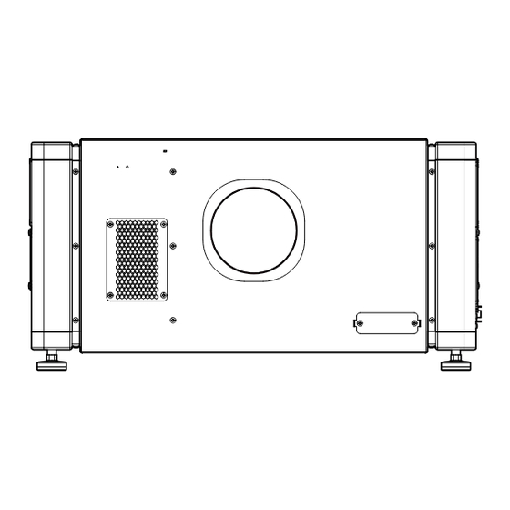
Names and Functions of Parts Front/Right, Left and Rear Side Intake air Intake air Intake air Intake air Intake air Exhaust air A Air Inlet/Filter D Lens Mounting Bracket The air inlets absorb air to cool the interior of the Mount the optional projection lens. -
Page 10: Right Side
Right Side DVI 1 e-shift Sync DVI 2 DVI 3 STANDBY/ON OPERATE I/B RS-232C LAMP DVI 4 WARNING RS-232C H [e-shift Sync] Terminal Q [LAMP] Indicator (DLA-VS4810 only) This indicator lights up in yellow when the lifetime of the LD block exceeds 19,000 hours. This is the input terminal for e-shift sync signals. -
Page 11: Installation
Installation Please read the following carefully when installing this unit. Optional Projection Lens Mount the optional projection lens (P. 60). For details on mounting the lens, please consult your authorized dealer. Minimum Space Required Do not use a cover that may enclose this unit or block the air inlets/vent holes. Allow sufficient space around this unit. When this unit is enclosed in a space with dimensions as indicated below, ventilate accordingly so that the internal and external temperatures are the same. -
Page 12: Projector Installation Angle
Projector Installation Angle You can install this projector between ±90° both vertically and horizontally. CAUTION Vertical Angle Special expertise and techniques are required for mounting this unit. Be sure to ask your dealer or a specialist to perform mounting. The projector cannot be installed upside down. Adjusting the Inclination Adjust the horizontal angle of the projector. -
Page 13: Installing The Projector And Screen
Installing the Projector and Screen It is recommended that this projector be installed at right When shift amount in the right direction is +25 % angle to the screen. Install the projector such that the center of the lens is When a zoom lens (optional) is in use, you can make use aligned with the 1/4 position from the left edge of the of the lens shift feature of this projector to shift the... - Page 14 Movable Range of Projected Image Overlaying projected images (when zoom lens is in use) GL-MS4015SZ Zoom lens GL-MS4016SZ Zoom lens Projecting images by stacking projectors GL-MS4021SZ Zoom lens The lens shift feature enables you to use up to three stacked projectors at the same time. Stacking the projectors enhances the brightness level, Projected Image and helps to project images that are sufficiently bright...
- Page 15 Projecting images by arranging projectors When light passes through the glass of side by side projection booth The lens shift feature enables you to use up to two projectors that are arranged side by side. Arranging two projectors side by side enhances the brightness level, and helps to project images that are sufficiently bright even when the venue is relatively big or bright.
-
Page 16: Screen Size And Projection Distance
Screen Size and Projection Distance Adjust the distance from the lens to the screen to achieve your desired screen size. GL-MS4015SZ / GL-MS4016SZ / GL-MS4021SZ Zoom lens Projection distance Projection Screen Size Image Width GL-MS4015SZ GL-MS4016SZ GL-MS4021SZ (Diagonal Length) Tele End Wide End Tele End Wide End Tele End Wide End 50"... - Page 17 GL-MS4011S Short focal length lens Projection Screen Size (Diagonal Length) Image Width Projection distance 50" (Approx. 1.27 m) 1.10 m 1.16 m 60" (Approx. 1.52 m) 1.31 m 1.41 m 70" (Approx. 1.78 m) 1.53 m 1.66 m 80" (Approx. 2.03 m) 1.75 m 1.91 m 90"...
-
Page 18: Connecting Video Signals Of The Computer
Connecting Video Signals of the Computer Connection During Single-Screen Mode Display The single-screen mode displays signals (up to four signals) from a computer as a single video image. To select to the single-screen mode, set “Display Mode” in the “Setting” menu to “Single”. (P. 38) Possible Input Signals and Projected Image Computer Projector... - Page 19 Normal 2 Stripes DVI 1 DVI 1 DVI 3 4 Stripes Cross DVI 1 DVI 2 DVI 3 DVI 4 DVI 1 DVI 2 DVI 3 DVI 4 Connection During Single-Screen Mode Display Below is the connection example for four-channel signals from the computer. For two-channel signals from the computer, connect to the [DVI 1] and [DVI 3] terminals of this projector.
-
Page 20: Connection During Two-Screen/Four-Screen Mode Display
Connection During Two-Screen/Four-Screen Mode Display The two-screen/four-screen mode enables simultaneous display of signals from two or four computers. To select the two-screen mode, set “Display Mode” in the “Setting” menu to “Double”. To select the four-screen mode, set “Display Mode” to “Cross”. (P. 38) Possible Input Signals and Projected Image Computer Output Status... - Page 21 Connection Example During Two-Screen Mode Desktop Computer To DVI Terminal DVI 1 e-shift Sync DVI-D Cable DVI 2 (Sold Separately) DVI 3 STANDBY/ON OPERATE I/B RS-232C LAMP To DVI DVI 4 WARNING RS-232C Terminal Laptop Computer Connection Example During Four-Screen Mode Desktop Computer To DVI Terminal...
-
Page 22: Connection Using A Lan Cable
Connection Using a LAN Cable Connect this projector, the computer for controlling this projector, and the switching hub using LAN cables, followed by configuring the network. Connection Example When assigning a static IP address You can acquire the IP address from the controlling computer simply by configuring a network that consists of this projector, the controlling computer, and switching hub. -
Page 23: Specifications Of Pc For Controlling This Projector
Specifications of PC for Controlling this Projector Windows 7 (32-bit, 64-bit), Windows 8 (32-bit, 64-bit), Windows 10 (32-bit, 64-bit) Browser Internet Explorer 10, Internet Explorer 11, Google Chrome, Firefox MEMO Windows is either registered trademark or trademark of Microsoft Corporation in the United States and/or other countries. -
Page 24: Turning On The Main Power
When duplication occurs in the IP address, make sure that only one unit of DLA-VS4010 / DLA-VS4810 is connected on the same network (turn off the main power of the other DLA-VS4010 / DLA-VS4810 units). Allow a time interval of at least 10 minutes before accessing. If access fails, turn off the power of all network equipments on the same... -
Page 25: Ip Address Settings
Select “Internet Protocol(TCP/IP)” and click “Properties” Set the IP address A Select “Use the following IP address” B Set “IP address” (For example, use 192.168.0.100 when DLA-VS4010 / DLA-VS4810 is in its default settings) MEMO Make sure that you take note of the original IP address before altering. - Page 26 Setting (Changing) the IP address of this projector When using Internet Explorer Launch the Internet Explorer on the Check if the “Active scripting” of the computer Internet Explorer is disabled A Click “Tools” and select “Internet Options” Check if the proxy has been set in the B Click in the order of “Security”...
- Page 27 Enter “http://192.168.0.2” in the Click “Admin.Network” in the “Main” address field of the Internet Explorer, menu and click “Go” host PJ-1 user: advanced A login screen for this projector appears. Logout Power Warning Status Main Image PROJECTION None Setting http://192.168.0.2 Light Source Time Hide Convergence...
-
Page 28: Assigning Ip Address From The Dhcp Server
Assigning IP Address from the DHCP Server The IP address is automatically assigned by the DHCP server. After connecting, turn on the main power Refer to P. 22 on the details of connection. Refer to P. 24 on procedures to turn on the main power. Set the “DHCP Client”... -
Page 29: Projecting Image
Projecting Image If setting for this projector is not completed, refer to “User Settings Menu”P. 34 upon turning on the power and configure the settings accordingly. Once the basic settings are configured, this projector can be used by simply performing the following operation procedures. - Page 30 Adjust the zoom ratio (screen size) (when zoom lens is in use) You can adjust the focus using the “Zoom” item of the “Lens” menu. host PJ-1 user: root Logout Zoom Focus Shift Main Image Setting Convergence Lens Option License Test Pattern To enlarge the screen size: Press the “W”...
- Page 31 Adjust the focus You can adjust the focus using the “Focus” item of the “Lens” menu. To move the focus point closer: Press the “+” (Near) end of “Focus” To move the focus point away: Press the “-” (Far) end of “Focus” MEMO The focus changes each time you click on the inner buttons (a / b).
-
Page 32: Useful Features During Projection
Turn the main power at the rear of the projector unit to off [X] The [STANDBY/ON] indicator on the projector unit goes off. CAUTION Do not turn off the main power supply switch when in the cool down mode. Doing so may shorten the lamp life and cause a malfunction. -
Page 33: Displaying The Menu
Displaying the Menu Enter the IP address assigned in the address field of the Internet Explorer, and click “Go” (P. 27) Example: When IP address assigned is “192.168.0.2”, enter “http://192.168.0.2”. http://192.168.0.2 MEMO When “LAN Setting” in Internet Explorer is set to “Use a proxy server for your LAN” it may not be possible to designate addresses directly. -
Page 34: User Settings Menu
User Settings Menu After installation and connection are complete, perform the necessary adjustment and setting. Operate the menus using the computer’s browser to make adjustments and configure settings. User Settings Menu Structure Page Menu Name Page Display Item Simplified Description of Item (1) Main Power Power ON/OFF operation... -
Page 35: Main Menu
(1) Main Menu This menu displays the ON/OFF status of the power supply and information on signals input to the projector. host PJ-1 user: root Logout Power Warning Status Main Image PROJECTION None Setting Light Source Time Hide Convergence 10h59m Lens Option License... - Page 36 R indicates the factory default. Item Setting Value Description Warning Status Displays the latest error number. MEMO For details on the error code and description, please refer to “Warning Status”P. 54. “None” is displayed when no error is detected. Light Source Time Displays the lifetime of the LD block.
-
Page 37: Image Menu
(2) Image Menu This menu is used for adjusting the image quality. host PJ-1 user: root Logout Brightness Main Image Setting Green Convergence Blue Lens Option Contrast License Green Blue Gamma Hide R indicates the factory default. Item Setting Value Description Brightness For adjusting the brightness of the red, green, and blue colors. -
Page 38: Setting Menu
(3) Setting Menu This menu is used for specifying the input level of the terminal and the display mode. host PJ-1 user: root Logout Input Level Main 0-255(PC) 16-235 Image Setting Display Mode Convergence Lens Option License Single Double Cross R indicates the factory default. -
Page 39: Convergence Menu
(4) Convergence Menu This menu is used for correcting color shifts in the optical system. host PJ-1 user: root Logout Blue Main Image Setting Convergence Lens Option License Test Pattern R indicates the factory default. Item Setting Value Description For adjusting the horizontal/vertical position of red and blue colors on the image. -
Page 40: Lens Menu
(5) Lens Menu This menu is used for adjusting the projection lens. host PJ-1 user: root Logout Zoom Focus Shift Main Image Setting Convergence Lens Option License Test Pattern Item Setting Value Description Zoom For adjusting the zoom ratio (screen size). MEMO The zoom position changes each time the inner button is clicked. -
Page 41: Option Menu
(6) Option Menu This menu is used for specifying the settings for screen display method, LD block brightness and others. host PJ-1 user: root Logout Flip Main Horz. Vert. Image Setting Light Source Power Back Color Convergence Mode1 Mode2 Blue Black Lens Option... -
Page 42: Administrator Settings Menu
Administrator Settings Menu After installation and connection are complete, perform the necessary adjustment and setting. Operate the menus using the computer’s browser to make adjustments and configure settings. Administrator Settings Menu Structure For details on page menu (1) to (6), refer to “User Settings Menu” (P. 34 to 41). Page Menu Name Page Display Item Simplified Description of Item... -
Page 43: Admin.network Menu
(7) Admin.Network Menu For configuring the network settings. host PJ-1 user: advanced Logout Host Name Setting Main Host Name Image Setting IP Address Setting Convergence DHCP Client DHCP STATIC IP Lens IP Address 192.168.1.100 Option Admin.Network Subnet Mask 255.255.255.0 Admin.Mail Default Gateway 192.168.1.1 Admin.Option... - Page 44 R indicates the factory default. Item Setting Value Description Host Name Setting For specifying the host name. Host Name (Default Value: PJ******) MEMO You can change it to a random name. You can input up to 8 characters using single-byte alphanumeric characters and “-”.
-
Page 45: Admin.e-Mail Menu
(8) Admin.E-mail Menu This menu is for configuring the mail settings, which sends out an error message to the computer of the preset address when an abnormality occurs within this projector. host PJ-1 user: advanced Logout E-Mail Setting Main E-Mail Image Setting user@localhost... - Page 46 R indicates the factory default. Item Setting Value Description E-Mail Setting For configuring the e-mail feature. : Use the mail feature. E-Mail : Do not use the mail feature. R OFF E-Mail Sender For specifying the destination e-mail address of this projector. (Default Value: lower 3 bytes of the MAC address)
-
Page 47: Admin.option Menu
(9) Admin.Option Menu This menu is used for specifying the image and option settings as well as resetting the lifetime of the LD block. host PJ-1 user: advanced Logout Color Depth Frame Lock Main 8bit 12bit Image Setting Mech. Shutter High Altitude Convergence Lens... -
Page 48: Admin.signal Menu
(10) Admin.Signal Menu This menu is for configuring settings such as display format, and for rewriting EDID. host PJ-1 user: advanced Logout Force Signal Main Image Setting Convergence Signal Status Lens Rate(Hz) Pixel H Pixel V Link Option 60.00 2048 2400 Dual Admin.Network... - Page 49 R indicates the factory default. Item Setting Value Description Signal Status Displays information on the input signals. Same as “Signal Status” in the User Menu. : Displays the DVI input terminal number. Rate(Hz) Rate(Hz) : Displays the vertical frequency. Pixel H Pixel H : Displays the horizontal resolution.
-
Page 50: Troubleshooting
Troubleshooting Check the following points before sending this product for repair. The following phenomena are not malfunctions. If there is no abnormality on the screen when the phenomena below appear, they are not malfunctions. The top or front part as well as the rear of the projector unit is hot A creaking sound is heard from the projector Device noise is heard from the interior of the projector There is color bleeding on the screen... - Page 51 Video image does not Is the lens cap removed? Remove the lens cap. P. 9 appear Are devices properly Connect the devices correctly. P. 19, 21 connected? Is the power of the connected Turn on the power of the connected devices turned on? devices.
-
Page 52: What To Do When These Messages Are Displayed
What to do when these messages are displayed Messages are displayed when the LD block is exhausted or when a signal that is not usable is input. Message Lamp Time Over Message Cause (Details) Displayed when the lifetime of the LD block has exceeded 20,000 hours. The message is displayed for 3 minutes during each projection. -
Page 53: Warnings Using Indicators
Warnings Using Indicators The lifetime of the LD block and warning mode are indicated by the indicators. For indicator displays during normal operation, refer to the note below. Indicator Description STANDBY/ON LAMP WARNING When the lifetime of the LD block has exceeded 19,000 hours Light On When the lifetime of the LD block has exceeded... -
Page 54: Warning Status
MEMO Indicator display during normal condition. Indicator Description STANDBY/ON LAMP WARNING Light On (Red) When in the standby mode. Light On (Green) When power is supplied (operating mode). Blinking (Red) When cooling down (cool down mode). (P. 31) Blinking (Green) When the projected image is temporarily hidden. -
Page 55: Rs-232C Interface
RS-232C Interface You can control this projector via a computer by connecting the computer to this unit using a RS-232C cross cable (D- sub 9 pins). The commands to control this unit and the response data format against the received commands are explained here. For details, please consult your authorized dealer. - Page 56 Parameters used for the data format The following 2 types of parameters are used for command and response data: (1) ON/OFF (2) Special Parameter Each parameter is as follows: (1) ON/OFF Shows the status (ON or OFF) of the unit, such as POWER and HIDE. Character Meaning (2) Special parameters...
-
Page 57: Maintenance
If dirt has entered this product or if you need to purchase the filter, please consult the authorized dealer from which this product is purchased or any nearby JVC servicing center. CAUTION... - Page 58 CAUTION Remove the four screws on the inner side (for fastening the filter cover). Filter Cover Filter Filter Cover Sponge Remove the filter cover The filter is located at the front side of the projector unit. Remove the sponge and filter Hold the center of the filter using your fingers, and pull the filter toward you to remove it.
-
Page 59: Routine Servicing
Routine Servicing Clean dirt on the cabinet Do this with a soft cloth. In case of heavy soiling, soak a cloth in neutral detergent diluted with water, wring dry and wipe, followed by wiping again using a dry cloth. Pay attention to the following to prevent the cabinet from deteriorating in condition, getting damaged, or the paint from coming off. -
Page 60: Specifications
Performance guarantee: 1500 m and below 660 mm x 342 mm x 934 mm (Width x Height x Depth) Dimensions (Excluding lens and small protrusions) DLA-VS4010: 73.5 kg (Excluding lens) Mass DLA-VS4810: 74.5 kg (Excluding lens) Optical System Projection method D-ILA analog drive system ×... - Page 61 Optional Items Projection lens GL-MS4015SZ 1.50:1 to 1.84:1 1.22x zoom lens (80" to 300") GL-MS4016SZ 1.50:1 to 1.84:1 1.22x zoom lens (50" to 210") GL-MS4021SZ 2.15:1 to 3.65:1 1.69x zoom lens (80" to 300") GL-MS4011S 1:1.1 short focal length lens (50" to 250") Replacement filter/sponge (front) LC43010-003A (Filter) LC43030-003A (Sponge)
- Page 62 Pin Arrangement RS-232C Terminal Pin No. Signal Action Signal Direction PC " This Projector Incoming Data Outgoing Data This Projector " PC Signal Ground 1, 4, 6-9 DVI-D Terminal Pin No. Signal Pin No. Signal TMDS Data 2- TMDS Data 3+ TMDS Data 2+ TMDS +5 V Power Supply TMDS Data 2/4 Shield...
-
Page 63: Dimensional Outline Drawing
Dimensional Outline Drawing (Unit: mm) Top Surface Side Intake air Intake air DVI 1 e-shift Sync DVI 2 DVI 3 STANDBY/ON OPERATE I/B RS-232C LAMP DVI 4 WARNING RS-232C M10 hole (x 12) Tightening depth: 10 to 20 Front Rear Surface Exhaust air 676.5 Intake air... - Page 64 Importer (EU only) 12 Priestley Way, London NW2 7BA, UNITED KINGDOM Importeur (Nur EU) Konrad-Adenauer-Allee 1-11, 61118 Bad Vilbel, DEUTSCHLAND Importatore (Solo EU) Via G. Sirtori 7/9, 20129 Milano, ITALIA Importador (Solamente EU) Ctra. Rubi, 88 Edifi cio Can Castanyer, 08174 Sant Cugat del Valles, Barcelona, ESPAÑA Importeur (Alleen EU) Leuvensesteenweg 248J, 1800 Vilvoorde, BELGIQUE...
Need help?
Do you have a question about the DLA-VS4010 and is the answer not in the manual?
Questions and answers