
Subscribe to Our Youtube Channel
Related Manuals for CleaverBrooks CBEX Elite


Summary of Contents for CleaverBrooks CBEX Elite
- Page 1 CBEX Elite Packaged Boiler 100-1200 HP Operation and Maintenance Manual Part No. 750-368 11/2013...
- Page 2 WARNING ! DANGER DO NOT OPERATE, SERVICE, OR REPAIR THIS EQUIPMENT UNLESS YOU FULLY UNDERSTAND ALL APPLICABLE SECTIONS OF THIS MANUAL. DO NOT ALLOW OTHERS TO OPERATE, SERVICE, OR REPAIR THIS EQUIPMENT UNLESS THEY FULLY UNDERSTAND ALL APPLICABLE SECTIONS OF THIS MANUAL. FAILURE TO FOLLOW ALL APPLICABLE WARNINGS AND INSTRUCTIONS MAY RESULT IN SEVERE PERSONAL INJURY OR DEATH.
-
Page 3: Table Of Contents
CONTENTS Basics 1-1 CHAPTER 1 1.1 — Overview 1-1 1.2 — The Boiler 1-2 1.3 — Construction 1-3 1.4 — Steam Controls (all fuels) 1-3 1.5 — Hot Water Controls (all fuels) 1-6 1.6 — IFGR Components 1-7 1.7 — Fan/Motor Cassette 1-7 Burner and Fuel System 2-1 CHAPTER 2 2.1 —... - Page 4 Sequence of Operation 4-1 CHAPTER 4 4.1 — Overview 4-1 4.2 — Circuits and Interlocks 4-2 4.3 — Firing Rate Controls 4-3 4.4 — Sequence of Operation: Gas or Oil 4-3 4.5 — Flame Loss Sequence 4-5 Starting and Operating Instructions 5-1 CHAPTER 5 5.1 —...
- Page 5 Inspection and Maintenance 8-1 CHAPTER 8 8.1 — Overview 8-1 8.2 — Fireside Cleaning 8-3 8.3 — Water Level Controls 8-3 8.4 — Water Gauge Glass 8-5 8.5 — Electrical Controls 8-5 8.6 — Flame Safety Control 8-7 8.7 — Oil Burner Maintenance 8-9 8.8 —...
-
Page 7: Basics
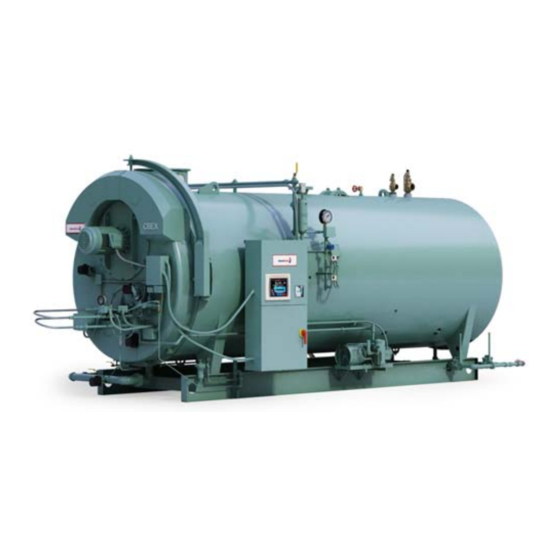
CHAPTER 1 1.1 — Overview CBEX Elite boilers are available for steam or hot water (100-800 HP only) applications. Basic construction con- sists of a cylindrical vessel with horizontal tubes passing through and connected to the front and rear tube sheets. -
Page 8: The Boiler
(IRI), Factory Mutual (FM), or other insuring underwriters requirements. 1.2 — The Boiler The CBEX Elite boiler is a packaged firetube boiler of welded steel construction and consists of a pressure vessel, burner, burner controls, forced draft fan, damper, air pump, refractory, and appropriate boiler trim. -
Page 9: Construction
Power Boilers, of the ASME Code. Hot water boilers designed for operating temperatures above 250º F or 125 psi are likewise built to Section I of the ASME Code. *CBEX Elite steam boilers are high pressure steam only. 1.4 — Steam Controls (all fuels) 1.4.1 —... - Page 10 The CB Level Master (for opera- tion and maintenance information, consult the Level Master manual that accompanied the boiler) is used on all steam boilers 150 psig to 250 psig. Low Water Cutoff FIGURE 1-3. 750-368 CBEX Elite 100-1200 HP...
- Page 11 Use only flat-jawed wrenches on the flats provided. When installing a flange connected valve, use a new gasket and draw the mounting bolts down evenly. Do not install or remove side outlet valves by using a pipe or wrench in the outlet. Safety Valve Piping and Safety Valves FIGURE 1-4. 750-368 CBEX Elite 100-1200 HP...
-
Page 12: Hot Water Controls (All Fuels)
Auxiliary Low Water Cutoff (optional): Breaks the circuit to stop burner operation if the water level in the boiler drops below the master low-water cutoff point. 750-368 CBEX Elite 100-1200 HP... -
Page 13: Ifgr Components
The front door davit arm can be used to remove the assembly (100-200 HP have a hinged front door and a davit specifically for blower use). When removing the cassette use the lifting lugs pro- vided (3-point rigging recommended for 350-1200 HP). Fan/Motor Cassette FIGURE 1-6. 750-368 CBEX Elite 100-1200 HP... - Page 14 Basics 750-368 CBEX Elite 100-1200 HP...
-
Page 15: Burner And Fuel System
The devices are wired into the circuitry to provide safe oper- ation and protect against incorrect operating techniques. All CBEX Elite boilers have the burner assembly integral with the front head. The entire head may be swung open for inspection and maintenance. -
Page 16: Front Head And Panel
It continues to monitor main flame (oil or gas) after expiration of pilot providing period. A standard equipped boiler has a lead sulfide (infrared sen- sitive) detector. 6. Stack Thermometer Indicates temperature of vented flue gases. 750-368 CBEX Elite 100-1200 HP... -
Page 17: Gas System
Refer to the Dimension Diagram (DD) pre- pared by Cleaver-Brooks for the installation. Item numbers refer to the table following the illustrations. Pilot Gas Train FIGURE 2-2. 750-368 CBEX Elite 100-1200 HP... - Page 18 The body of the gas valve has a plugged opening that is used whenever it is nec- essary to conduct a test for possible leakage across the closed valve. 10. Gas Regulating Actuator w/ Regulates gas pressure to the pressure range required by the burner. Includes proof-of-closure switch. 750-368 CBEX Elite 100-1200 HP...
-
Page 19: Oil System
(100 and 200 series only). Low Oil Pressure Switch Switch contacts open when the fuel oil pressure drops below selected pressure. (optional) Switch will interrupt the limit circuit upon loss of sufficient fuel oil pressure for correct combustion. 750-368 CBEX Elite 100-1200 HP... -
Page 20: Controls For Combination Burners
The use of a Variable Speed Drive (VSD), optional, works in conjunction with the air damper actuator. When high fire is not required the VSD reduces amperage to the fan motor, reducing energy consumption and the corre- sponding air flow simultaneously. Secondary Air Flow Diagram FIGURE 2-4. 750-368 CBEX Elite 100-1200 HP... -
Page 21: Automatic Ignition
Some of the primary air is also used to assist the oil pressure regulators of the fuel oil controller. Further explana- tion is given in Chapter 5. 750-368 CBEX Elite 100-1200 HP... -
Page 22: Oil Fuel Flow
Burner and Fuel System 2.9 — Oil Fuel Flow In Figure 2-9 the oil flow is indicated by arrows and the pertinent controls are identified. Diagram for Light Oil Flow FIGURE 2-5. 750-368 CBEX Elite 100-1200 HP... -
Page 23: Gas Fuel Flow
A combustion curve for each fuel is programmed into the Hawk controls during boiler commissioning. The com- bustion curve settings will determine how the butterfly gas valve (or the oil metering valve), air damper, and FGR 750-368 CBEX Elite 100-1200 HP... -
Page 24: Ultra Low Nox Systems
A feature designed into the control program maintains the boiler in the low-fire position during ignition and keeps it there until the main flame is established. 2.12 — Ultra Low NOx Systems For Ultra low NOx (<15 PPM) operation refer to the NTI burner manual 750-220. 750-368 2-10 CBEX Elite 100-1200 HP... -
Page 25: Waterside Care
The dip tube reduces the possibility of air, which may be trapped at the top of the shell, from entering into the system. 750-368 CBEX Elite 100-1200 HP... - Page 26 NOTE: If the operating water temperature going to the system must be lower than 170º F, the operating boiler water temperature should be a minimum of 170º F and mixing valves should be used to avoid damage to the equipment. 750-368 CBEX Elite 100-1200 HP...
- Page 27 It is recommended that the system circulating pumps take suction from the outlet connection on the boiler, and that they discharge to the system load. The suction side is preferred because it decreases air entry into the sys- tem and does not impose the system head on the boiler. 750-368 CBEX Elite 100-1200 HP...
- Page 28 It cannot be over-emphasized that rapid changes in temperature within the boiler can, and sometimes do, cause damage. 3.2.2 — Steam Boilers Feed Pump Operation 750-368 CBEX Elite 100-1200 HP...
-
Page 29: Water Treatment
Prevent hard scale deposits or soft sludge deposits, which reduce heat transfer and can lead to overheated metal and costly downtime and repairs. Eliminate corrosive gases in the supply or boiler water. Prevent inter-crystalline cracking or caustic embrittlement of boiler metal. 750-368 CBEX Elite 100-1200 HP... -
Page 30: Cleaning
The pressure vessel and the steam and return lines or hot water piping represent, in effect, a closed system. Although the steam and return (condensate) lines or the hot water piping system may have been previously cleaned, it is possible that: Cleaning has been inadequate. 750-368 CBEX Elite 100-1200 HP... -
Page 31: Boil-Out Of A New Unit
Failure to follow these instructions could result in serious injury or death. The suggested general procedure for cleaning a boiler is: Refer to the table below to determine water capacity. Have sufficient cleaning material on hand to complete the job. 750-368 CBEX Elite 100-1200 HP... - Page 32 Allow a small amount of fresh water to enter the boiler to create a slight overflow that will carry off surface impurities. Continue the boil and overflow process until the water clears. Shut the burner down. Let the boiler cool to 120º F or less. 750-368 CBEX Elite 100-1200 HP...
-
Page 33: Washing Out
The inspections will indicate the effectiveness of the feedwater treatment. The effectiveness of treatment, the water conditions, and the amount of fresh water make-up required are all factors to be considered in establishing frequency of future pressure vessel washouts. Contact your local Cleaver-Brooks authorized representative for more information. 750-368 CBEX Elite 100-1200 HP... -
Page 34: Blowdown: Steam Boiler
The surface blowoff opening, when furnished, is on the top center line of the pressure vessel. It is provided with an internal collecting pipe terminating slightly below the working water level for the purpose of skimming TDS, oil, or other impurities from the surface of the pressure vessel water. 750-368 3-10 CBEX Elite 100-1200 HP... - Page 35 Larger vessels may have two or three bottom blowdown lines, each with a quick opening valve. Lines may be blown down simultaneously by opening all quick opening valves before opening the downstream valve. When opening the slow opening valve, crack it slightly to allow the lines to warm, then continue opening slowly. 750-368 3-11 CBEX Elite 100-1200 HP...
-
Page 36: Periodic Inspection
When shutting down the boiler, the load should be reduced gradually and the pressure vessel cooled at a rate that avoids damaging temperature differential that can cause harmful stresses. Vessels should not normally be drained until all pressure is relieved, to prevent uneven contraction and temperature differentials that can cause 750-368 3-12 CBEX Elite 100-1200 HP... -
Page 37: Preparation For Extended Layup
Although pollution control regulations may continue to limit the permissible sulphur content of fuel oils, care must be taken to avoid corrosion problems that sulphur can cause, especially in a boiler that is seasonally shut 750-368 3-13 CBEX Elite 100-1200 HP... - Page 38 Additional chemicals may be suggested by your local Cleaver-Brooks authorized representative to minimize corrosion. Internal water pressure should be maintained at greater than atmospheric pressure. Nitrogen is often used to pressurize the vessel. 750-368 3-14 CBEX Elite 100-1200 HP...
-
Page 39: Sequence Of Operation
Air compressor motor starter (if provided). c. Oil pump motor starter (if provided). • The load demand light is on. Chapters 5 and 6 contain operating instructions and specific information on setting and adjusting the controls. 750-368 CBEX Elite 100-1200 HP... -
Page 40: Circuits And Interlocks
Flame Detector Circuit Flame detector (FD) • Main fuel valve circuit • • Man gas valve (MGV) • Man gas vent valve (MGVV) - if provided Oil valve (OV) • Main fuel valve light FVL) • 750-368 CBEX Elite 100-1200 HP... -
Page 41: Firing Rate Controls
The controls wired into the Running Interlock circuit must be closed within 10 seconds after the start sequence. In the event any of the controls are not closed at this time, or if they subsequently open, the boiler will go into a safety shutdown. 750-368 CBEX Elite 100-1200 HP... - Page 42 The actuators for fuel, air, and FGR are positioned independently via Modbus signal. The burner starting cycle is now complete. the LDL and FVL lights on the panel remain lit. Demand firing contin- ues as required by load conditions. 750-368 CBEX Elite 100-1200 HP...
-
Page 43: Flame Loss Sequence
Pilot but no main flame: When the pilot flame is proven, the main fuel valve circuit is energized. Depending upon the length of the trial-for-ignition period, the pilot flame will be extinguished 10 or 15 seconds later. The 750-368 CBEX Elite 100-1200 HP... - Page 44 Preventive maintenance and scheduled inspection of all components should be followed. Periodic checking of the relay is recommended to see that a safety lockout will occur under conditions of failure to ignite either pilot or main flame, or from loss of flame. 750-368 CBEX Elite 100-1200 HP...
-
Page 45: Starting And Operating Instructions
Refer to Chapter 3 for water requirements. On a steam boiler, open the test valve to vent air displaced during filling. Leave the test valve open until steam is noted after the burner is operating. 750-368 CBEX Elite 100-1200 HP... -
Page 46: Control Settings: Steam And Hot Water
In the event the boiler is equipped with optional control devices not listed here, be certain to ascertain that their settings are correct. If additional information is required, see your local Cleaver-Brooks authorized representative or contact Cleaver-Brooks. 750-368 CBEX Elite 100-1200 HP... -
Page 47: Gas Pilot
The burner will cycle to the low-fire pre-purge position and stop there. Observe the reading on the air pressure gauge. With no oil flow, the pressure should be a minimum of 7 psi. 750-368 CBEX Elite 100-1200 HP... -
Page 48: Firing Preparations For No. 2 Oil (Series 100-200)
If the fuel oil supply originates from a pressurized loop, it is assumed that the pressure of the loop will be at a minimum of 75 psi. Under these conditions, the relief valve at the terminal block should be adjusted to the point 750-368 CBEX Elite 100-1200 HP... - Page 49 The pressure gauge will indicate a higher reading when air is present and the flame exists and will increase as the firing rate increases. After the burner is firing and when the air pump is running, final adjustment can be made at the fuel oil controller. 750-368 CBEX Elite 100-1200 HP...
-
Page 50: Firing Preparations For Gas (Series 200-700)
Should the information not be readily available, consult the Cleaver-Brooks Service Department and be ready to provide the boiler serial number. Chapter 6 contains additional information along with standard gas flow and pressure requirements. 750-368 CBEX Elite 100-1200 HP... - Page 51 When the conditions covered above in Section 5.1 - 5.6 are assured, the burner is ready for firing. 750-368 CBEX Elite 100-1200 HP...
-
Page 52: Startup, Operating, And Shutdown: All Fuels
Operate at the increased fuel input rate for a period of time until an increase is noted in pressure or temperature. 750-368 CBEX Elite 100-1200 HP... - Page 53 At the end of the programmed post-purge period, the blower motor is turned off. The air pump motor of an oil fired burner is also turned off. The timer has returned to its original starting position and stops. The unit is ready to restart. 750-368 CBEX Elite 100-1200 HP...
-
Page 54: Control Operational Checks
The situation is especially true in new installations. Promptly correct any conditions causing leakage. Failure to follow these instruc- tions could result in serious injury or death. 750-368 5-10 CBEX Elite 100-1200 HP... -
Page 55: Adjustment Procedures
• The Modulating and Flame Safeguard controls, which provide for modulated firing and burner sequencing/ flame supervision. On a standard CBEX Elite these functions are managed by the Hawk integrated control sys- tem, comprising both hardware (PLC, Input/Output devices, and touchscreen HMI) and software (program- ming for the PLC and HMI). - Page 56 The burner will be “on” whenever the pressure or temperature is less than point B and “off” whenever pressure or temperature is greater than point A. The distance between points A and B represents the “on-off” differential of the operating limit control. 750-368 CBEX Elite 100-1200 HP...
- Page 57 It is therefore prudent to set the modulating control a few pounds or degrees below the operating control allowing the Low Fire to “catch the load” before releasing to modulation. 750-368 CBEX Elite 100-1200 HP...
-
Page 58: Operating Limit Pressure Control
In addition, approximately one-half minute is required for the damper actuator to travel from low- to high-fire. The time lag may allow pressure or temperature to drop below desirable limits. 750-368 CBEX Elite 100-1200 HP... -
Page 59: Operating Limit Temperature Control: Hot Water
The run/test switch on the program relay should be set to “Test.” Turn the burner switch on. The blower will start (provided that all limit circuits are completed) and the programmer will remain in the low-fire (damper closed) portion of the pre-purge. Combustion Air Proving Switch FIGURE 6-3. 750-368 CBEX Elite 100-1200 HP... -
Page 60: Atomizing Air Proving Switch
The flame must be sufficient to ignite the main flame and to be seen by the flame detector. But an extremely large flame is not required. An overly rich flame can cause sooting or carbon buildup on the flame detector. Too small a flame can cause ignition problems. 750-368 CBEX Elite 100-1200 HP... - Page 61 To make the final adjustment, slowly close the gas pilot adjusting cock until the flame can no longer be seen through the sight tube. Then slowly open the cock until a flame providing full sight tube coverage is observed. 750-368 CBEX Elite 100-1200 HP...
-
Page 62: Gas Pressure And Flow Information
The gas pressure regulator must be adjusted to achieve the pressure to assure full input. The pressure requirement varies with boiler size, altitude, and type of gas train. Refer to Table 6.1 for pressure requirements. 750-368 CBEX Elite 100-1200 HP... - Page 63 1.07 2500 1.09 3000 1.11 4000 1.16 5000 1.21 6000 1.25 7000 1.30 8000 1.35 9000 1.40 NOTE: For undersized or oversized gas trains or altitudes above 9000 feet, contact your local Cleaver-Brooks repre- sentative. 750-368 CBEX Elite 100-1200 HP...
- Page 64 This answer indicates the number of cubic feet at line pressure which must pass through the meter to deliver the equivalent number of cubic feet at base pressure. 750-368 6-10 CBEX Elite 100-1200 HP...
-
Page 65: Adjusting Combustion
Your gas supplier can, if necessary, furnish exact correction factors that take into consideration Btu content, exact base pressure, specific gravity, temperature, etc., of the gas used. 6.12 — Adjusting Combustion Combustion settings are made using the Hawk control system. Refer to manual included with the boiler con- trols. 750-368 6-11 CBEX Elite 100-1200 HP... -
Page 66: Low Gas Pressure Switch
Unnecessary shutdowns may result if the setting is too close to normal, however, regulations require that the setting may not be greater than 150% of rated pressure. Manual resetting is necessary after a pressure rise. Press the reset lever after pressure falls. 750-368 6-12 CBEX Elite 100-1200 HP... -
Page 67: Burner Drawer Adjustment
Adjustment of the switch must be such that its contacts open if the oil nozzle lance is not properly positioned for oil firing. The switch is electrically removed from the circuit when a combination fuel burner is fired on gas (fuel selector switch is in GAS position). 750-368 6-13 CBEX Elite 100-1200 HP... - Page 68 Adjustment Procedures 750-368 6-14 CBEX Elite 100-1200 HP...
-
Page 69: Troubleshooting
Warning Disconnect and lock out the main power supply in order to avoid the hazard of electrical shock. Failure to follow these instructions could result in serious injury or death. 750-368 CBEX Elite 100-1200 HP... -
Page 70: Problem-Cause Suggestions
B. Damper jammed. Running interlock circuit not completed. A. Combustion or atomizing air proving switches defective or not properly set. B. Motor starter interlock contact not closed. Flame detector defective, sight tube obstructed, or lens dirty. 750-368 CBEX Elite 100-1200 HP... - Page 71 Improper air/fuel ratio (lean fire): A. Slipping linkage. B. Damper stuck open. C. Fluctuating fuel supply: 1) Temporary obstruction in fuel line. 2) Temporary drop in gas pressure. Interlock device inoperative or defective. 750-368 CBEX Elite 100-1200 HP...
- Page 72 Troubleshooting 750-368 CBEX Elite 100-1200 HP...
-
Page 73: Inspection And Maintenance
Any leaks — fuel, water, steam, exhaust gas — should be repaired promptly and under conditions that observe necessary safety precautions. Preventive maintenance measures, such as regularly checking the tightness of connections, locknuts, setscrews, packing glands, etc., should be included in regular maintenance activities. 750-368 CBEX Elite 100-1200 HP... - Page 74 NOTE: To ensure proper operation, use only Cleaver-Brooks genuine parts. Contact your local Cleaver-Brooks repre- sentative for parts information and ordering. 750-368 CBEX Elite 100-1200 HP...
-
Page 75: Fireside Cleaning
The need to periodically check water level controls and the waterside of the pressure vessel cannot be overem- phasized. Most instances of major boiler damage are the result of operating with low water, or the use of untreated or incorrectly treated water. 750-368 CBEX Elite 100-1200 HP... - Page 76 Controls must be mounted in a plumb position for proper performance. Determine that piping is vertically aligned after shipment and installation and throughout life of equipment. A blowdown of the water controls on a steam boiler should be performed daily. Open the drain valve slowly to prevent float damage. 750-368 CBEX Elite 100-1200 HP...
-
Page 77: Water Gauge Glass
Be certain that controls are correctly leveled. The internal piping leading to the pressure control actuators should be cleaned, if necessary. Covers should be left on controls at all times. 750-368 CBEX Elite 100-1200 HP... - Page 78 Power supply to the boiler must be protected with dual element fuses (Fusetrons®) or circuit breakers. Similar fuses should be used in branch circuits. Standard one-shot fuses are not recommended. Information given below is included for guidance to fuse requirements. 750-368 CBEX Elite 100-1200 HP...
-
Page 79: Flame Safety Control
Also check to see that the amplifier and the program module are tightly inserted. The relay's self-diagnostic ability includes advising when it or its plug-in modules are at fault and require replace- ment. 750-368 CBEX Elite 100-1200 HP... - Page 80 The flame failure light (and optional alarm) will be activated. The blower motor will run through the post-purge and stop. Turn the burner switch off. Reset the safety switch. Re-establish main fuel supply. 750-368 CBEX Elite 100-1200 HP...
-
Page 81: Oil Burner Maintenance
The design of the burner should be kept operationally clean when firing on oil. A routine check and any necessary cleaning should be made during off periods or when the burner is firing on gas. 750-368 CBEX Elite 100-1200 HP... - Page 82 Replace strainer by screwing it into the nozzle body only finger tight. Do not use an orifice of a size other than originally installed. Back Pressure Orifice FIGURE 8-8. 750-368 8-10 CBEX Elite 100-1200 HP...
-
Page 83: Gas Burner Maintenance
There should be 1/4” between the edge of the diffuser fins and the gas spuds when the burner is installed. Check to see that the diffuser fins do not interfere with the gas ports or gas spuds in the burner hous- ing. 750-368 8-11 CBEX Elite 100-1200 HP... -
Page 84: Motorized Gas Valve
Check the ignition cables for cracks in the insulation. Verify that all connections between the transformer and the electrode are tight. 8.8.1 — Burner Removal, Sizes 900-1200 Removal of the burner assembly on the CBEX Elite 900-1200 (see Figure 8-10) requires the burner removal kit 880-03675. -
Page 85: Air Control Damper
Combustion should be checked and readjusted as required whenever the burner is removed or any control linkage is disturbed. Failure to follow these instructions could result in equipment damage. Inspection of the air damper should be performed on a more frequent basis if the boiler is operating in a dirty environment. 750-368 8-13 CBEX Elite 100-1200 HP... -
Page 86: Fan/Motor Cassette Removal
3 inches for 250-500 units. Remove the fan/motor cassette fastening nuts. Swing the fan/motor cassette to the side and secure it to the boiler using high strength cord. Do not over- extend the motor wires. 750-368 8-14 CBEX Elite 100-1200 HP... -
Page 87: Ifgr Inspection And Adjustment
B. Adjust the retainers for the correct impeller clearance at two housing attachment points 180º apart. C. Adjust the retainers for correct clearance at the housing attachment points 90º from those initially adjusted. D. Adjust for correct impeller clearance at the remaining attachment points. 750-368 8-15 CBEX Elite 100-1200 HP... -
Page 88: Fan/Motor Cassette Installation
Sections VI and VII of the ASME Boiler and Pressure Vessel Code. Safety Valves FIGURE 8-13. 750-368 8-16 CBEX Elite 100-1200 HP... -
Page 89: Fuel Oil Metering Valve
Withdraw the metering vale stem and spring. Do not drop or mishandle. Check for nicks or scratches. Check that the pin holding the metering portion is not protruding. Back off the packing gland. 750-368 8-17 CBEX Elite 100-1200 HP... - Page 90 Snug the packing gland, but only sufficiently to place slight tension on the packing. The stem must move freely from the force of the spring. Work the stem up and down several times to ensure that it moves freely. 750-368 8-18 CBEX Elite 100-1200 HP...
-
Page 91: Air Pump And Lubricating System
LUBE OIL AIR / OIL TANK LUBE OIL COOLING COIL COOLER AIR PUMP MOTOR MOTOR AIR FILTER SIGHT GLASS AIR PUMP (LUBE OIL LEVEL) CHECK VALVE 900-1200 HP 100-800 HP Air Pump FIGURE 8-17. 750-368 8-19 CBEX Elite 100-1200 HP... - Page 92 After the last pad is in place, slip the retainer screen onto the cylinder. Be sure to fit an o-ring gasket under the cover so that a tight seal is obtained. Follow previous instructions for oil replacement. 750-368 8-20 CBEX Elite 100-1200 HP...
- Page 93 (gap) alignment. Parallel misalignment exists when shaft axes are parallel but not concentric. Angular mis- alignment is the reverse situation, with shaft axes concentric but not parallel. Flexible Coupling Alignment FIGURE 8-19. 750-368 8-21 CBEX Elite 100-1200 HP...
- Page 94 Leave the rear pump bracket (coupling end) in place to aid in realignment of the replacement pump. Do this by removing the two capscrews that extend through the bracket into the pump housing. Temporarily leave the front bracket attached to the pump. 750-368 8-22 CBEX Elite 100-1200 HP...
- Page 95 The air pump should rotate in a clockwise direction, as viewed from the drive shaft end. Keep the motor and other components free from dust and dirt to prevent overheating and damage. Motor lubrica- tion should follow manufacturer’s recommendations. 750-368 8-23 CBEX Elite 100-1200 HP...
-
Page 96: Refractory
Should segments of the liner burn away or fall out, replace the entire refractory piece. Any refractory that may break out should be removed as soon as detected so that it will not fuse to the bottom of the furnace and obstruct the flame. 750-368 8-24 CBEX Elite 100-1200 HP... - Page 97 Allow refractory to air dry as long as possible. If immediate use is required, fire intermittently at a low rate for several hours to thoroughly dry the refractory. For detailed information, request Bulletin C10-5921 from your local Cleaver-Brooks representative. 750-368 8-25 CBEX Elite 100-1200 HP...
- Page 98 Install both pieces of cerafelt and continue laying furnace tiles to complete the last two rows. After joint cement hardens (approximately 2 hours), remove bricking tool, wooden tile supports, and discard cerafelt shims. Liner tile installation FIGURE 8-23. 750-368 8-26 CBEX Elite 100-1200 HP...
-
Page 99: Front Door And Rear Access Plug
After the boiler is back in operation, re-tighten the door bolts to com- pensate for compression of the gasket or movement of the door. Tighten the Davit Nut FIGURE 8-25. 750-368 8-27 CBEX Elite 100-1200 HP... -
Page 100: Lubrication
The filler and drain plugs should be thoroughly cleaned before they are replaced. The lubricant used should be clean and equal to one of the good commercial grades of grease locally available. Some commercially available lubricants are: • Gulf Oil - Precision Grease No. 2 750-368 8-28 CBEX Elite 100-1200 HP... -
Page 101: Combustion Adjustments
Area Source boilers and Major Source boilers.* Instructions for determining your facility’s Source category, as well as your boiler’s subcategory (based on boiler size, age, and fuel type) can be found on the Cleaver-Brooks web site at http://www.cleaverbrooks.com/Reference-Center/EPA-Compliance/Index.aspx. 750-368 8-29 CBEX Elite 100-1200 HP... - Page 102 *A Major Source facility emits 10 or more tons per year of any single air toxic or 25 tons or more per year of any combination of air toxics. If your facility does not meet the criteria for a Major Source, it is considered an Area Source. 750-368 8-30 CBEX Elite 100-1200 HP...
-
Page 103: Parts
Repair and replacement parts should be ordered from your local Cleaver-Brooks authorized representative. VESSEL SIZE BOILER HP 55” 100-125 60” 150-200 67” 250-300 78” 350-400 85” 500-600 92” 700-800 106” 900-1200 750-368 CBEX Elite 100-1200 HP... -
Page 104: Arch Brick & Liner Tiles
094-01037 ARCH BRICK see table 10 lbs 872-00390 CEMENT, JOINT MORTAR 872-00518 BULK INSULATION 972 IN^2 ITEM #3 ITEM #4 BOILER HP 094-01010 094-00205 500-600 094-01036 094-00747 700-800 900-1000 094-01062 094-01064 1100-1200 094-00938 094-00939 750-368 CBEX Elite 100-1200 HP... -
Page 105: Blower Cassette
40-C-618 40-C-502 40-C-502 NOTE: Impeller size is based on boiler hp, ppm emission level, boiler operating pressure and altitude. To ensure proper sizing, contact Cleaver-Brooks Aftermarket. For blower gasket components see 9.19 — Fireside Gaskets 750-368 CBEX Elite 100-1200 HP... - Page 106 2 Pole w/ 1.15 SF Motor HP 3 PH 60 HZ 3 PH 60 HZ 3 PH 60 HZ 3 PH 50 HZ 894-4036 894-4045 894-4054 894-4063 894-4037 894-4046 894-4055 894-4064 894-4038 894-4047 894-4056 894-4065 750-368 CBEX Elite 100-1200 HP...
- Page 107 894-04722 894-04066 894-05014 894-04040 894-05002 894-04049 894-04716 894-04058 894-04723 894-04067 894-05015 894-04041 894-05003 894-04050 894-04717 894-04059 894-05008 894-04068 894-05016 894-04042 894-05004 894-04051 894-04718 894-04060 894-05009 894-04069 894-05017 894-04043 894-05005 894-04052 894-04719 894-04061 894-05010 894-04070 894-05018 750-368 CBEX Elite 100-1200 HP...
- Page 108 BASE, MOTOR MOUNTING 003-02266-000 003-02266-000 003-02266-000 003-02266-000 MOTOR 894-04118-000 085-03432-000 SUPPORT, MOTOR 085-03432-000 085-03432-000 085-03432-000 059-08479-000 GUSSET, MOTOR SUPPORT 059-08479-000 059-08479-000 059-08479-000 077-00480-000 SPACER, IMPELLER 841-00334-000 FAN WHEEL 813-00387-000 SPACER, IMPELLER 077-00446-000 NUT, SELF LOCKING JAM 869-00445-000 750-368 CBEX Elite 100-1200 HP...
-
Page 109: Main Gas Train
945-00238 945-00238 945-00238 Gas Valve Body 949-00461 949-00447 949-00448 949-00448 949-00445 949-00446 Item Description 100-125 350-400 500HP 600HP 700-800 LGPS 817-02418 817-03591 LUB Plug Valve 941-00129 941-00130 941-00130 Ball Valve 941-02640 941-02640 941-02640 941-02640 941-02640 750-368 CBEX Elite 100-1200 HP... -
Page 110: Starter Gas Train
Parts 9.4 — Starter Gas Train Item Description 100-125 150-200 250-300 350-400 500-600 700-800 Butterfly Valve 940-00133 940-00133 940-00134 940-00134 940-00134 940-00134 750-368 CBEX Elite 100-1200 HP... -
Page 111: Pilot Gas Train
250-300 350-400 500-600 700-800 Gas Cock 825-00030 825-00030 825-00030 825-00030 825-00030 825-00030 Solenoid Valve 948-00197 948-00197 948-00197 948-00197 948-00197 948-00197 Regulator 918-00356 918-00356 918-00356 918-00356 918-00356 918-00356 Pressure Gauge 850-00109 850-00109 850-00109 850-00109 850-00109 850-00109 750-368 CBEX Elite 100-1200 HP... -
Page 112: Actuator Assembly, Fuel Oil
Oil Valve Stem SEE CHART Oil Stem Chart Boiler Size Stem Number 100 HP 024-00095 125, 150 HP 024-00096 200 HP 024-00097 250-350 HP 024-00098 400 HP 024-00099 500-700 HP 024-00100 800 HP 024-00101 9-10 750-368 CBEX Elite 100-1200 HP... -
Page 113: Actuator Assembly, Air Damper
— Actuator Assembly, Air Damper 9.7 — Actuator Assembly, Air Damper Item Description Part # Actuator, Servo 945-00260 Motor 9.8 — Actuator Assembly, IFGR Valve Item Description Part # Actuator, 945-00259 Servo Motor 750-368 9-11 CBEX Elite 100-1200 HP... -
Page 114: Actuator Assembly, Gas Butterfly Valve
Parts 9.9 — Actuator Assembly, Gas Butterfly Valve Item Description Part # Actuator, Universal Parallel Positioning 945-229 9-12 750-368 CBEX Elite 100-1200 HP... -
Page 115: Pressure Controls
Part # Part # Part # Part # Pressure Gauge 850-00222 850-00222 850-00320 850-00400 Transmitter 817-04867 817-04868 817-04868 817-04868 Op. Limit Pressure Control 817-04093 817-04883 817-04147 817-04091 High Limit Pressure Control 817-04092 817-04148 817-04149 817-04073 750-368 9-13 CBEX Elite 100-1200 HP... -
Page 116: Water Column, Lwco
Gate Valve 100-200 941-00170 Water Column, Level Master 250-800 289-00831 289-00831 289-00831 Sensor Assembly, Level Master 250-800 623-00230 623-00230 623-00230 Ball Valve 250-800 941-00055 941-02656 941-02656 Ball Valve 250-800 941-01790 Gate Valve 250-800 941-00170 941-00170 9-14 750-368 CBEX Elite 100-1200 HP... -
Page 117: Auxiliary Low Water Cutoff
Gate Valve 100-800 941-00170 McD-M ALWCO Control 100-800 817-2407 150S-B-M Gate Valve 100-800 941-00170 McD-M 93-M ALWCO Control 100-800 817-00435 Gate Valve 100-800 941-00170 McD-M 94-M ALWCO 100-800 817-00306 817-00306 Gate Valve 100-800 941-00170 941-00170 750-368 9-15 CBEX Elite 100-1200 HP... -
Page 118: Blower Davit: 55" & 60
Parts 9.13 — Blower Davit: 55” & 60” 55” 60” Item Description Part # Part # Davit Arm Assembly 287-00052 287-00052 Threaded Rod 841-01047 841-01047 Davit Pin 056-00043 056-00043 9-16 750-368 CBEX Elite 100-1200 HP... -
Page 119: Front Head Hinge: 55" & 60
9.14 — Front Head Hinge: 55” & 60” 55” 60” Item Description Part # Part # Eyebolt, Door Hinge (Lower) 007-00061 007-00061 Eyebolt, Door Hinge (Upper) 007-00058 007-00058 Retaining Ring 914-00147 914-00147 Hinge Pin 056-00002 056-00002 Oil Gun Bracket 008-03328 008-03328 750-368 9-17 CBEX Elite 100-1200 HP... -
Page 120: Front Davit Assembly
Oil Gun Mounting Bracket 008-03326 008-03328 008-03328 008-03328 Double Row Ball Bearing 807-00031 807-00031 807-00324 807-00324 807-00324 Front Hinge Pin 056-00026 056-00026 056-00027 056-00027 056-00027 Spacer 077-00386 077-00386 077-00386 077-00386 952-00250 Washer 952-00250 952-00250 952-00250 952-00250 952-00250 9-18 750-368 CBEX Elite 100-1200 HP... -
Page 121: Front Head Assembly
Housing to Head Gasket 032-03175 032-03171 Blanket Insulation 872-01084 872-01084 Screen 930-00135 930-00135 150oz Coating Cement Rigidizer 872-00443 872-00443 Plate 077-02126 077-02126 Front Door Hinge 462-00183 462-00183 Gusset 059-09727 059-00805 Front Head Interior Insulation 465-02731 465-01675 750-368 9-19 CBEX Elite 100-1200 HP... - Page 122 Front Head Ring 080-00951 Air Duct Assembly 039-01733 Front Head 132-02700 103-00097 Davit Support 085-03301 Front Head Support 085-01542 Head Plate Gasket 032-02619 Blanket Insulation 872-01084 Screen 930-00135 Interior Insulation 465-02484 180oz Coating Cement Rigidizer 872-00443 9-20 750-368 CBEX Elite 100-1200 HP...
- Page 123 032-00898 Blanket Insulation 872-01084 Screen 930-00135 Interior Insulation See Table 180oz Coating Cement Rigidizer 872-00443 Assembly No. IFGR Plate Item #1 Item #11 132-02683 (RH) 30 ppm 132-02682 465-01680 132-02740 (RH) 60 ppm 132-02682 750-368 9-21 CBEX Elite 100-1200 HP...
- Page 124 Assembly No. IFGR Plate Item #1 Item #11 85” 132-02675 (RH) 30 ppm 132-02674 465-02366 85” 132-02736 (RH) 60 ppm 132-02674 92” 132-02694 (RH) 30 ppm 132-02695 465-02655 92” 132-02744 (RH) 60 ppm 132-02695 9-22 750-368 CBEX Elite 100-1200 HP...
- Page 125 — Front Head Assembly 9.16.5 — 106” 10 29 6 14 15 750-368 9-23 CBEX Elite 100-1200 HP...
-
Page 126: Burner Installation
057-05027 Front Head Gasket 032-03173 032-03173 Support to Housing Gasket 032-03174 032-03174 Burner Support Housing 040-00879 040-00879 Housing to Front Head Gasket 032-00603 032-00603 Burner to Housing Gasket 032-00605 032-00605 Burner Drawer 429-01702 429-01703 9-24 750-368 CBEX Elite 100-1200 HP... - Page 127 032-00105 032-02602 032-00899 Burner Support to Housing Gasket 032-03170 032-00928 032-00928 Housing to Front Head Gasket 032-00603 032-02625 032-02625 Burner Support 085-03463 085-00444 085-00444 Burner Drawer 429-01668 429-01537 429-01477 Burner to Housing Gasket 032-00605 750-368 9-25 CBEX Elite 100-1200 HP...
- Page 128 Parts 9.17.3 — 85”, 92” 21 15 9-26 750-368 CBEX Elite 100-1200 HP...
- Page 129 700 HP 30-60 PPM 700 FUEL 040-00836-000 800 HP 30-60 PPM 100 FUEL 800 HP 30-60 PPM 101 FUEL 800 HP 30-60 PPM 200 FUEL 429-01724-000 040-00836-000 800 HP 30-60 PPM 700 FUEL 040-00836-000 750-368 9-27 CBEX Elite 100-1200 HP...
- Page 130 853-09296-000 TAPE, SILICONE, 3/8" X 1-1/2" X 8.3 FT. LG. 032-02680-000 GASKET, BURNER SUPPORT, BURNER DRAWER, & FRONT HEAD 040-00746-000 HOUSING, BURNER SUPPORT, 106" DIA. CBEX-ELITE BOILERS 006-00459-000 GLIDE BAR, 900-1200 HP BURNER SUPPORT 9-28 750-368 CBEX Elite 100-1200 HP...
-
Page 131: Fireside Gaskets
— Fireside Gaskets 9.18 — Fireside Gaskets 750-368 9-29 CBEX Elite 100-1200 HP... - Page 132 Parts Fireside Gaskets (cont’d) 9-30 750-368 CBEX Elite 100-1200 HP...
- Page 134 Web Address: http://www.cleaverbrooks.com...
Need help?
Do you have a question about the CBEX Elite and is the answer not in the manual?
Questions and answers