
Subscribe to Our Youtube Channel
Related Manuals for CleaverBrooks CBLE


Summary of Contents for CleaverBrooks CBLE
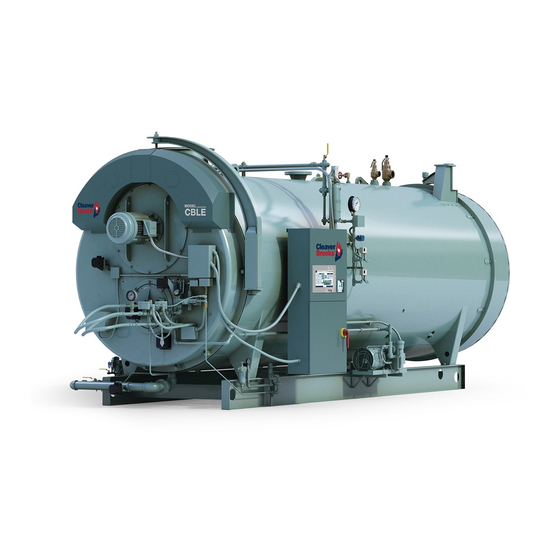
- Page 1 Table Of Contents Compliments of Power Mechanical, Inc. Used Boilers Rental Boilers Model CBLE Packaged Boiler 250 - 350 HP Light OIl, Heavy Oil, Gas, or Combination Operation and Maintenance Manual 750-91 12/09...
- Page 2 WARNING ! DANGER WARNING ! DANGER If the information in this manual is not fol- Improper installation, adjustment, service, or maintenance can cause equipment damage, per- lowed exactly, a fire or explosion may re- sonal injury, or death. Refer to the Operation and sult causing property damage, personal Maintenance manual provided with the boiler.
- Page 3 CLEAVER-BROOKS Model CBLE 250-350 HP Light Oil, Heavy Oil, Gas, or Combination Operation and Maintenance Manual Cleaver-Brooks 2009 Please direct purchase orders for replacement manuals to your local Cleaver-Brooks authorized representative Manual Part No. 750-91 Printed in U.S.A. 12/09...
- Page 4 WARNING ! DANGER DO NOT OPERATE, SERVICE, OR REPAIR THIS EQUIPMENT UNLESS YOU FULLY UNDERSTAND ALL APPLICABLE SECTIONS OF THIS MANUAL. DO NOT ALLOW OTHERS TO OPERATE, SERVICE, OR REPAIR THIS EQUIPMENT UNLESS THEY FULLY UNDERSTAND ALL APPLICABLE SECTIONS OF THIS MANUAL. FAILURE TO FOLLOW ALL APPLICABLE WARNINGS AND INSTRUCTIONS MAY RESULT IN SEVERE PERSONAL INJURY OR DEATH.
-
Page 5: Table Of Contents
Model CB-LE Packaged Boiler 250-350 HP 750-91 Table of Contents Basics of Firetube Operation 1-1 CHAPTER 1 1.1 — Introduction 1-1 1.2 — The Boiler 1-3 1.3 — Construction 1-4 1.4 — Steam Controls (All Fuels) 1-5 1.4.1 — Operating Limit Pressure Control 1-5 1.4.2 —... - Page 6 Burner Operation and Control 2-1 CHAPTER 2 2.1 — The Burner 2-1 2.2 — Control and Component Function 2-3 2.3 — Components Common to All Boilers 2-3 2.4 — Controls for Gas Firing 2-5 2.5 — Controls Common to Oil-Fired Boilers 2-9 2.6 —...
- Page 7 3.2.2 — Water Circulation 3-2 3.2.2.1 — Multiple Boiler Installations 3-3 3.2.2.2 — Pump Location 3-4 3.2.2.3 — Pump Operation 3-4 3.2.3 — Pressure 3-4 3.3 — Water Requirements: Steam Boiler 3-5 3.3.1 — Feed Pump Operation 3-5 3.3.2 — Water Feeder (optional) Operation 3-6 3.4 —...
- Page 8 4.4 — Flame Loss Sequence 4-5 4.4.1 — No Pilot Flame 4-6 4.4.2 — Pilot But No Main Flame 4-6 4.4.3 — Loss of Flame 4-6 Starting and Operating Instructions 5-1 CHAPTER 5 5.1 — Preparation for Startup: All Fuels 5-1 5.2 —...
- Page 9 Adjustment Procedures 6-1 CHAPTER 6 6.1 — Overview 6-1 6.1.1 — High Turndown Burner 6-1 6.2 — Linkage: Modulating Motor and Air Damper 6-2 6.3 — Modulating Motor 6-4 6.4 — Modulating Motor Switches: Low-Fire and High-Fire 6-4 6.5 — Burner Operating Controls: General 6-5 6.6 —...
- Page 10 6.18 — Low-Gas Pressure Switch 6-21 6.19 — High-Gas Pressure Switch 6-21 6.20 — Fuel Oil Pressure and Temperature: General 6-22 6.21 — Fuel Oil Combustion Adjustment 6-23 6.21.1 — Standard Burner Low-Fire Adjustment: Heavy Oil 6-25 6.21.2 — High Turndown Burner Low-Fire Adjustment: Light Oil 6-25 6.22 —...
- Page 11 8.3 — Water Level Controls 8-3 8.3.1 — Steam Boiler 8-3 8.3.2 — Hot Water Boiler 8-4 8.4 — Water Gauge Glass 8-4 8.5 — Electrical Controls 8-4 8.6 — Flame Safety Control 8-6 8.6.1 — Checking Pilot Flame Failure 8-6 8.6.2 —...
- Page 12 8.19.1 — Air Compressor 8-20 8.19.2 — Lubricating Oil 8-20 8.19.3 — Lubricating Oil Strainer and Cooling Coil 8-21 8.19.4 — Air Cleaner 8-21 8.19.5 — Air-Oil Tank 8-21 8.19.6 — Lube Oil Cooling Coil 8-22 8.19.7 — Flexible Coupling Alignment 8-22 8.19.8 —...
- Page 13 9.2.9 — Front Head Insulation 9-12 9.2.10 — Front Head Linkage 9-13 9.2.11 — Gas Train 9-14 9.2.12 — Light Oil/Air Piping 9-16 9.2.13 — Heavy Oil/Air Piping 9-18 9.2.14 — Heavy OIl Alstrom Heater 9-20 9.2.15 — CB-LE IFGR 9-22 9.2.16 —...
- Page 14 750-91 (revised 2009) Model CB-LE Packaged Boiler Manual...
-
Page 15: Basics Of Firetube Operation
The general information in this manual applies directly to Cleaver-Brooks Model CBLE Boilers in sizes ranging from 250 through 350 boiler horsepower for the following fuels: •... - Page 16 Basics of Firetube Operation Firetube Boiler (cutaway view) FIGURE 1-1. Rated Capacity 250 through 350 hp Operating Pressure Steam: 15 - 250 psig, or higher if specified Hot Water: 30 - 250 psig, or higher if specified Fuel Oil or Gas or Combination Ignition Automatic Firing...
-
Page 17: The Boiler
IFGR damper, fan, and motor sizes. When firing heavy oil in a gas/oil CBLE boiler, the heavy oil isolation valve is required in order to protect the IFGR system from soot buildup and corrosion. See CB manual 750-171 for operating details on the Heavy Oil Iso- lation system. -
Page 18: Construction
Basics of Firetube Operation ness or physical characteristics of the pressure vessel parts of the boiler. Typically, the safety valves are set at or below design pressure. Operating pressure is the pressure of the boiler at which it normally operates. The operating pressure usually is maintained at a suitable level below the setting of the pressure relieving valve(s) to prevent their frequent opening during normal operation. -
Page 19: Steam Controls (All Fuels)
1.4 — Steam Controls (All Fuels) Steam Boiler: Light Oil or Gas Fired FIGURE 1-2. 1.4 — Steam Controls (All Fuels) 1.4.1 — Operating Limit Pressure Control Breaks a circuit to stop burner operation on a rise of boiler pressure at a selected setting. It is adjusted to stop or start the burner at a preselected pressure setting. -
Page 20: Modulating Pressure Control
Basics of Firetube Operation 1.4.3 — Modulating Pressure Control Senses changing boiler pressures and transmits the information to the modulating motor to change the burner fir- ing rate when the manual-automatic switch is set on “automatic.” Boiler Controls FIGURE 1-3. 1.4.4 —... -
Page 21: Water Column Drain Valve
1.4 — Steam Controls (All Fuels) 1.4.6 — Water Column Drain Valve Provided so that the water column and its piping can be flushed regularly to assist in maintaining cross-connecting piping and in keeping the float bowl clean and free of sediment. A similar drain valve is furnished with auxiliary low-water cutoff for the same purpose. - Page 22 Basics of Firetube Operation prevent buildup of back pressure and accumulation of foreign material around the valve seat area. Apply only a moderate amount of pipe compound to male threads and avoid overtightening, which can distort the seats. Use only flat-jawed wrenches on the flats provided. When installing a flange-connected valve, use a new gasket and draw the mounting bolts down evenly.
-
Page 23: Hot Water Controls (All Fuels)
1.5 — Hot Water Controls (All Fuels) 1.5 — Hot Water Controls (All Fuels) 1.5.1 — Water Pressure and Temperature Gauge Indicates the internal water pressure and the boiler water temperature. Water Pressure and Temperature Gauge & Limit Controls (configurations will vary) FIGURE 1-6. -
Page 24: Auxiliary Low-Water Cutoff (Optional)
Basics of Firetube Operation 1.5.6 — Auxiliary Low-Water Cutoff (optional) Breaks the circuit to stop burner operation if the water level in the boiler drops below the master low-water cutoff point. 1.5.7 — Safety Valve(s) Relieves the boiler of pressure higher than the design pressure or a lower pressure, if designated. Relief valves and their discharge piping are to be installed to conform to ASME Code requirements. -
Page 25: Over-Travel Mechanism
1.6 — IFGR Components 1.6.3 — Over-Travel Mechanism The over-travel mechanism has two functions. It allows the linkage to pass through the front door, and it allows jackshaft rotation to exceed (over-travel) IFGR linkage movement. A set of springs allows the linkage to stay in a fixed position while the jackshaft rotates. -
Page 26: Fan/Motor Cassette
Basics of Firetube Operation 1.6.5 — Fan/Motor Cassette The fan and motor assemblies are designed as a cassette so that they can be removed from the front of the boiler without opening the front door. The front door davit arm can be used to remove the assembly. Fan/Motor Cassette FIGURE 1-9. -
Page 27: Revised 2009)
The devices are wired into the circuitry to provide safe operation and protect against incorrect operating techniques. All CBLE boilers have the burner assembly attached to the front head. The entire head may be swung open for inspection and maintenance. -
Page 28: Control And Component Function
Burner Operation and Control Combustion air is provided by a centrifugal blower located in the front head. Combustion air delivery to the burner is under the control of the modulating motor. The motor also regulates the flow of fuel through a linkage system connected to the gas butterfly valve and/or oil through a cam operated metering valve. - Page 29 2.3 — Components Common to All Boilers Component Description Forced Draft Fan Motor Starter Energizes forced draft fan (blower) motor. Ignition Transformer Provides high voltage spark for ignition of gas pilot or light oil pilot. Low Fire Switch An internal auxiliary switch, cam actuated by the motor shaft, which must be closed to indicate that the air damper and fuel metering valve are in the low fire position before an ignition cycle can occur.
-
Page 30: Controls For Gas Firing
Burner Operation and Control Component Description Indicator Lights Provide visual information of boiler operation as follows: Flame Failure • Load Demand • Fuel Valve (valve open) • Low Water • Program Relay and Flame Safeguard Control Automatically programs each starting, operating, and shutdown period in conjunction with operating limit and interlock devices. - Page 31 2.4 — Controls for Gas Firing Component Description Gas Modulating Cam An assembly, consisting of a quadrant, a series of adjustable allen- head screws, and a contour spring, provided for adjustment of gas input at any point in the modulating range. Main Gas Cock For manually opening and closing the main fuel gas supply down- stream of the main gas line pressure regulator.
- Page 32 Burner Operation and Control Gas Train (configurations may vary) FIGURE 2-1. Gas Modulating Cam FIGURE 2-2. 750-91 (revised 2009) Model CB-LE Packaged Boiler Manual...
- Page 33 2.4 — Controls for Gas Firing Secondary Air Flow with Gas Train FIGURE 2-3. 750-91 (revised 2009) Model CB-LE Packaged Boiler Manual...
-
Page 34: Controls Common To Oil-Fired Boilers
Burner Operation and Control 2.5 — Controls Common to Oil-Fired Boilers The following items are applicable to all oil-fired or gas and oil-fired boilers. Additional controls for No. 6 oil are listed in section 2.6. Front of Burner Drawer. FIGURE 2-4. Component Description Oil Drawer Switch... - Page 35 2.5 — Controls Common to Oil-Fired Boilers Component Description Fuel Oil Controller An assembly combining into a single unit the gauges, regulators, and valves required for regulating the flow of fuel oil. All controllers have the following integral parts. In addition to these, the controller used on a No.
- Page 36 Burner Operation and Control Component Description Air Pump Module Assembly Provides the compressed air required to atomize the fuel oil for proper combustion. It is started automatically by the programmer’s sequence. Components include: Air Pump Motor: Drives the air pump and an air cooling fan. •...
- Page 37 2.5 — Controls Common to Oil-Fired Boilers Oil Control Valve Assembly - Heavy Oil FIGURE 2-6. Air Pump Components FIGURE 2-7. 750-91 (revised 2009) 2-11 Model CB-LE Packaged Boiler Manual...
-
Page 38: Additional Controls For Heavy Oil
Burner Operation and Control 2.6 — Additional Controls for Heavy Oil The oil heater is provided to heat heavy oil to the point where it can be effectively atomized and burned. Most heavy oil heaters utilize an electric heater to reduce the viscosity of the heavy oil until steam or hot water is available to the oil heater shell. - Page 39 2.6 — Additional Controls for Heavy Oil Component Description Low Oil Temperature Switch Thermostatic switch that prevents burner from starting, or stops burner firing if fuel oil temperature is lower than required for oil burner operation. Oil Supply Pressure Gauge Indicates fuel oil pressure in the oil heater and supply pressure to the fuel oil controller’s pressure regulator.
-
Page 40: Controls For Combination Burners Only
Burner Operation and Control Component Description Manual Bypass Valve Provided as a timer saver in establishing oil flow. When open, it per- mits circulation of oil through the supply and return lines. The valve MUST be closed prior to initial light off. Orifice Oil Control Valve Valve may be opened prior to startup to aid in establishing fuel oil flow through the controller. -
Page 41: Combustion Air
2.8 — Combustion Air 2.8 — Combustion Air Air for combustion of fuel (referred to as “secondary” air) is furnished by the forced draft fan mounted in the boiler head. In operation, air pressure is built up in the entire head and is forced through a diffuser plate for a thorough mixture with the fuel for proper combustion. -
Page 42: Atomizing Air
Burner Operation and Control 2.10 — Atomizing Air Air for atomizing the fuel oil (referred to as “primary” air) is pumped by the air pump into the air-oil receiver tank and delivered under pressure through a manifold block to the oil burner nozzle. The atomizing air mixes with the fuel oil just prior to the oil leaving the nozzle. - Page 43 2.11 — Oil Fuel Flow: Light Oil Light Oil Flow Diagram FIGURE 2-10. 750-91 (revised 2009) 2-17 Model CB-LE Packaged Boiler Manual...
-
Page 44: Oil Fuel Flow: Heavy Oil
Burner Operation and Control 2.12 — Oil Fuel Flow: Heavy Oil Fuel oil is delivered into the system by the fuel oil supply pump which delivers part of its discharge to the oil heater. The remainder of the fuel oil returns to the oil storage tank through a fuel oil relief valve and oil return line (see Figure 2-11). - Page 45 2.12 — Oil Fuel Flow: Heavy Oil No. 6 Heavy Oil Flow Diagram (Steam-Electric Heater) FIGURE 2-11. 750-91 (revised 2009) 2-19 Model CB-LE Packaged Boiler Manual...
-
Page 46: Gas Fuel Flow
Burner Operation and Control 2.13 — Gas Fuel Flow Metered gas from the utility flows through the pressure regulator at a reduced pressure suitable to burner require- ments, through the main gas shutoff cock, main gas valve(s), and modulating butterfly gas valve to the non-premix orifice-type burner. - Page 47 2.14 — Modulating Firing of the motor. The switch must be closed to establish that the damper and fuel metering valves are in the low-fire position before the programmer commences into the ignition period. During this time, neither the manual flame control nor the modulating control have any control over the damper motor, regardless of their setting.
- Page 48 Burner Operation and Control 2-22 750-91 (revised 2009) Model CB-LE Packaged Boiler Manual...
-
Page 49: Waterside Care And Requirements
Waterside Care and CHAPTER 3 Requirements 3.1 — Overview The operator should be familiar with this chapter before attempting to place the unit into operation. Although it is of prime importance, the subject of water supply and treatment cannot adequately be covered in this manual. -
Page 50: Minimum Water Temperature
Waterside Care and Requirements The air vent tapping on the top center line of the boiler should be piped into the expansion or compression tank. Air trapped at the top of the boiler will find its way out of the boiler through the tapping. 3.2.1.1 —... -
Page 51: Multiple Boiler Installations
3.2 — Water Requirements: Hot Water Boiler SYSTEM TEMPERATURE DROP - DEGREES °F BOILER BOILER OUT- SIZE PUT (1000) (BHP) BTU/HR MAXIMUM CIRCULATING RATE - GPM 1,005 1,340 1,675 2,010 2,345 2,680 3,350 4,185 5,025 1,005 6,695 1,340 8,370 1,675 10,045 2,010 1,005... -
Page 52: Pump Location
Waterside Care and Requirements 3.2.2.2 — Pump Location It is recommended that the system circulating pumps take suction from the outlet connection on the boiler, and that they discharge to the system load in order to put the boiler and the expansion tank on the suction side of the pump. -
Page 53: Water Requirements: Steam Boiler
3.3 — Water Requirements: Steam Boiler When initially firing a newly installed boiler, or when cutting an existing boiler into an operating system, the boiler or boilers to be cut into operation MUST be pressurized equal to the system and/or other boilers prior to opening the header valves. -
Page 54: Water Feeder (Optional) Operation
Waterside Care and Requirements 3.3.2 — Water Feeder (optional) Operation Water feeder operation is usually applicable to boilers operating at 15 psi steam or less. It is only necessary to open the water supply line valve and the water feeder discharge valve. NOTE: In the event that water column isolation valves are provided or installed, it must be established that the valves are open and seated or locked in the open position. -
Page 55: Cleaning
3.5 — Cleaning A properly sized water meter should be installed in the raw water make-up line in order to accurately determine the amount of raw water admitted to the boiler (steam or hot water) and to aid in maintaining proper waterside condi- tions. -
Page 56: Boil-Out Of A New Unit
Waterside Care and Requirements Any sludge, mud, or sediment found will need to be flushed out. If excessive mud or sludge is noticed during the blowdown, the scheduling or frequency of blowdown may need to be revised. The need for periodic draining or washout will also be indicated. - Page 57 3.6 — Boil-Out of a New Unit Fill the pressure vessel with clean water until the top of the tubes is covered. Add the cleaning solution and then fill to the top. The temperature of the water used in the initial fill should be at ambient temperature. The boiler should then be fired intermittently at a low rate sufficient to hold solution just at the boiling point.
-
Page 58: Washing Out
Waterside Care and Requirements 3.7 — Washing Out 3.7.1 — Hot Water Boiler In theory, a hot water system and boiler that has been initially cleaned, filled with raw water (and water treated), and with no make-up water added, will require no further cleaning or treatment. However, since the system (new or old) can allow entrance of air and unnoticed or undetected leakage of water, introductions of raw water make-up or air may lead to pitting, corrosion, and formation of sludge, sediment, scale, etc. -
Page 59: Intermittent Manual Blowdown
3.8 — Blowdown: Steam Boiler Scale has a low heat transfer value and acts as an insulation barrier. Scale retards heat transfer, which not only results in lower operating efficiency, and consequently higher fuel consumption, but more importantly, can cause overheating of boiler metal. -
Page 60: Manual Blowdown Procedure
Waterside Care and Requirements When surface or continuous blowdown is not utilized, manual blowdown is used to control the dissolved or sus- pended solids in addition to the sludge. In practice, the valve(s) of the bottom blowdown are opened periodically in accordance with an operating schedule and/or chemical control tests. -
Page 61: Periodic Inspection
3.9 — Periodic Inspection Slightly crack the downstream valve and then close it tightly. Under not circumstances should a blow-off valve be left open and the operator should never leave until the blow- down operation is completed and the valves are closed. 3.9 —... -
Page 62: Preparation For Extended Lay-Up
Waterside Care and Requirements Check all water and steam piping and valves for leaks, wear, corrosion, and other damage. Replace or repair as required. 3.10 — Preparation for Extended Lay-Up Many boilers used for heating or seasonal loads or for standby service may have extended periods of non-use. Spe- cial attention must be given to idle boilers so that neither waterside nor fireside surfaces are allowed to deteriorate from corrosion. - Page 63 3.10 — Preparation for Extended Lay-Up water and steam valves should be closed. Damper and vents should be closed to prevent air from reaching fireside surfaces. Periodic inspection should be made and absorption materials renewed. Wet storage is generally used for a boiler held in stand-by condition or in cases where dry storage is not practical. The possibility of freezing temperatures must be considered.
- Page 64 Waterside Care and Requirements 3-16 750-91 (revised 2009) Model CB-LE Packaged Boiler Manual...
-
Page 65: Sequence Of Operation
Sequence of Operation CHAPTER 4 4.1 — Overview Chapter 4 outlines the electrical sequencing of various controls through the pre-purge, ignition, run, and shutdown cycles of the burner. The program relay establishes the sequence of operation and directs the operation of all other controls and compo- nents to provide an overall operating sequence. -
Page 66: Circuit And Interlock Controls
Sequence of Operation 4.2 — Circuit and Interlock Controls The burner control circuit is a two-wire system designed for 115 Vac, 60 Hz, single-phase power. The electrical portion of the boiler is made up of individual circuits with controls that are wired in a manner designed to provide a safe workable system. -
Page 67: Sequence Of Operation: Oil Or Gas
4.3 — Sequence of Operation: Oil or Gas Circuit Components Firing Rate Circuit Damper motor transformer (DMT) • Modulating damper motor (MDM) • Manual-automatic switch (MAS) • Manual flame control (MFC) • Modulating control (MC) • High Fire Proving Circuit High fire switch (HFS) •... -
Page 68: Ignition Cycle
Sequence of Operation To assure that the system is in low fire position prior to ignition, the low fire switch (LFS) must be closed to com- plete the “low fire proving circuit.” The sequence will stop and hold until the modulating damper motor (MDM) has returned to the low fire position and the contacts of the low fire switch (LFS) are closed. -
Page 69: Flame Loss Sequence
4.4 — Flame Loss Sequence damper and fuel valves are actuated by the motor through a linkage and cam assembly to provide modulated firing rates. NOTE: Normal operation of the burner should be with the switch in the manual-automatic position and under the direction of the modulating control. -
Page 70: No Pilot Flame
Sequence of Operation Caution The lockout switch must be manually reset following a safety shutdown. The cause for loss of flame or any unusual condition should be investigated and corrected before attempting to restart. Failure to follow these instructions could cause damage to the equipment. - Page 71 4.4 — Flame Loss Sequence Knowledge of the system and its controls will make troubleshooting much easier. Costly down time or delays can be prevented by systematic checks of the actual operation against the normal sequence to determine the stage at which performance deviates from normal.
- Page 72 Sequence of Operation 750-91 (revised 2009) Model CB-LE Packaged Boiler Manual...
-
Page 73: Starting And Operating Instructions
Starting and Operating CHAPTER 5 Instructions 5.1 — Preparation for Startup: All Fuels The instructions in Chapter 5 are all based upon installation being complete and all electrical, fuel, water, and vent stack connections are made. The operator should be familiar with the burner, boiler, and all controls and components. To quickly locate and identify the various controls and components mentioned the following paragraphs, refer to the illustrations and the contents of Chapters 1, 2, and 3. -
Page 74: Control Settings: Steam And Hot Water
Starting and Operating Instructions Warning Prior to firing a boiler, be sure that discharge piping from safety valves or relief valves, and discharge piping from all blowdown and drain valves, is piped to a SAFE point of discharge, so that emission of hot water or steam cannot pos- sibly cause injury. -
Page 75: Modulating Control
5.3 — Gas Pilot • On a hot water boiler, the high limit temperature control should be 5º to 10º F above the operating limit tem- perature control setting but within the limits of the design pressure of the pressure vessel. 5.2.3 —... -
Page 76: Atomizing Air
Starting and Operating Instructions On initial starting attempts, several efforts might be required to fully bleed the pilot line. While checking pilot adjustment, observe whether the pilot flame is extinguished promptly when the burner switch is opened. A linger- ing flame indicates a leaking gas pilot valve, which is a condition requiring correction before proceeding. 5.4 —... -
Page 77: Firing Preparations For No. 2 Oil (Series 100 - 200)
5.5 — Firing Preparations for No. 2 Oil (Series 100 - 200) Observe the reading on the air pressure gauge. With no oil flow, the pressure should be a minimum of 7 psi. If there is no pressure, determine the cause and correct it before proceeding. Check for obstructions in the air inlet line, incorrect rotation (air pump rotation is clockwise), or a loose oil nozzle or other leaks. -
Page 78: Oil Pressure
Starting and Operating Instructions Observe the regulated oil pressure gauge for indication that flow is established. If no pressure shows on the gauge after a few moments, stop the oil pump and re-prime. If the supply tank is lower than the pump, it is possible that the initial priming of the suction line, followed by operation of the pump, will not establish oil flow. -
Page 79: Starting
5.6 — Firing Preparation for No. 6 Oil (Series 400 - 600) The pressure gauge will indicate a higher reading when the flame is present and will increase as the firing rate increases. After the burner is firing and when the air pump is running, final adjustment can be made at the fuel oil controller. -
Page 80: Oil Pressure
Starting and Operating Instructions Momentarily energize the fuel oil pump starter to check for proper pump rotation. With the rotation verified, prime the suction line strainer with oil and turn the fuel oil pump switch to the “ON” position. Check the oil supply pressure gauge for indication that oil flow is established. If no pressure shows on the gauge after a few moments, stop the oil pump and re-prime. -
Page 81: Starting
5.7 — Firing Preparations for Gas (Series 200-400-700) The electric heater on burners equipped for No. 6 fuel oil is sized so that it is capable of supplying heated oil at a rate no greater than that required for low fire operation and is primarily supplied for convenience on cold starts. - Page 82 Starting and Operating Instructions prepared to provide the correct boiler serial number. Chapter 6 contains additional information along with stan- dard gas flow and pressure requirements. If the burner is a combination fuel model, set the gas/oil switch to “gas.” Withdraw the oil burner gun and latch it in its rearward (OUT) position.
-
Page 83: Ifgr Setup
5.8 — IFGR Setup Investigate and correct the cause of the valve leakage before relighting the burner. NOTE: The main gas valve should provide a tight seal, provided nothing prevents tight closure. Foreign material may be present in either the new or renovated gas lines unless adequate care is taken in cleaning and purging. When the conditions covered in Section 5.7 and in Sections 5.1, 5.2, and 5.3 are assured, the burner is ready for fir- ing. - Page 84 Starting and Operating Instructions Jackshaft Linkage Settings FIGURE 5-6. Overtravel Linkage Settings FIGURE 5-7. 5-12 750-91 (revised 2009) Model CB-LE Packaged Boiler Manual...
-
Page 85: Startup, Operating And Shutdown: All Fuels
5.9 — Startup, Operating and Shutdown: All Fuels Flange Collar and Damper Settings (Top View) FIGURE 5-8. 5.9 — Startup, Operating and Shutdown: All Fuels Depending upon the fuel being burned, the applicable previous sections in this chapter should be reviewed for pre- liminary instructions. -
Page 86: Operating
Starting and Operating Instructions On ignition failure, the flame failure light will glow and the blower will purge the boiler of unburned fuel vapors before stopping. After ignition failure, wait a few moments before resetting the lockout switch. Warning Do not re-light the pilot or attempt to start the main burner, either oil or gas, if the combustion chamber is hot and/or if gas or oil vapor combustion gasses are present in the furnace or flue passages. -
Page 87: Shutdown
5.10 — Control Operational Test and Checks • The burner is manually turned “off.” • The low-water condition is detected by low-water level control. • The electrical or fuel supply is interrupted. • The combustion air pressure or atomizing air pressure drops below minimum level. NOTE: There can be other reasons for shutdown, such as motor overload, flame outages, tripped circuit breakers, blown fuses, or through other interlock devices in the circuitry. - Page 88 Starting and Operating Instructions sure increases. Observe the steam gauge to check the cutoff pressure as the operating limit control shuts the burner down. Slowly open the header valve to release steam pressure and check the cut-in setting as the burner restarts. Check the modulating control for the desired operating pressure range.
-
Page 89: Adjustment Procedures
Adjustment Procedures CHAPTER 6 6.1 — Overview Each Cleaver-Brooks boiler is tested for correct operation before shipment from the factory. However, variable conditions such as burning characteristics of the fuel and operating load conditions may require further adjustment after installation to assure maximum operating efficiency and economy. A combustion efficiency analysis made during the initial startup will help to determine what additional adjustments are required in a particular installation. -
Page 90: Linkage: Modulating Motor And Air Damper
Adjustment Procedures 6.2 — Linkage: Modulating Motor and Air Damper The linkage consists of various arms, connecting rods, and swivel ball joints that transmit motion form the modu- lating motor to the metering cam(s), rotary air damper, and gas butterfly valve. NOTE: On combination gas and oil boilers, the gas butterfly valve might not be used. - Page 91 6.2 — Linkage: Modulating Motor and Air Damper Complete Linkage Assembly: Combination Gas and Oil FIGURE 6-2. The stop screw in the rotary air damper limits damper travel at both closed (low-fire) and fully opened (high-fire) positions. The screw is provided so that it is possible to tell, even with the burner in place, whether the damper rotor is in fully opened or closed position.
-
Page 92: Modulating Motor
Adjustment Procedures 6.3 — Modulating Motor The modulating motor has a 90º shaft rotation. The motor manufacturer also provides a 160º stroke model for other applications. If a replacement is obtained from someone other than a Cleaver-Brooks Service or Parts repre- sentative, it may have an incorrect stroke. -
Page 93: Burner Operating Controls: General
6.5 — Burner Operating Controls: General 6.5 — Burner Operating Controls: General NOTE: Adjustments to the boiler operating controls should be made by an authorized Cleaver-Brooks Service Tech- nician. Refer to the appropriate boiler operation and maintenance manual for specific information on boiler startup and operation. - Page 94 Adjustment Procedures Separate and independent controls affect modulated firing and burner on-off cycling. Firing Graph FIGURE 6-4. The burner will be “on” whenever the pressure or temperature is less than point B (see Figure 6-4) and “off ” whenever pressure or temperature is greater than point A. The distance between points A and B represents the “on-off ”...
- Page 95 6.5 — Burner Operating Controls: General When set as shown, with a time lag between B and C, the burner will be in a low-fire position upon a restart and will fire at that rate for a short period of time before falling pressure or temperature requires an increase in the fir- ing rate.
-
Page 96: Modulating Pressure Control: Steam
Adjustment Procedures In the setting of the controls, consideration must be given to the time required for a burner restart. Each start, requires a pre-purge period, plus the fixed time required for proving the pilot and main flame. In addition, approx- imately one-half minute is required for the damper motor to travel from low to high-fire. -
Page 97: Operating Limit Temperature Control: Hot Water
6.10 — Operating Limit Temperature Control: Hot Water Hot Water Controls FIGURE 6-5. With the cover off, turn the adjustment wheel until the pointer indicates the desired range. Caution To prevent burner shutdown at other than low-fire setting, adjust the modulating pressure control to modulate to low- fire BEFORE the operating limit pressure control shuts off the burner. -
Page 98: Low Water Cutoff Devices: Steam & Hot Water
Adjustment Procedures 6.12 — Low Water Cutoff Devices: Steam & Hot Water No adjustment is required since LWCO controls are preset by the original manufacturer. However, if the water level is not properly maintained, inspect the devices immediately and replace as required. 6.13 —... -
Page 99: Gas Pilot Flame Adjustment
6.15 — Gas Pilot Flame Adjustment Since the adjustment of the air switch may be made either during the damper closed or damper open position of pre-purge, it is also possible to make the adjustment with the relay stopped in the damper open position in a similar manner to the adjustment of the combustion air proving switch described in Section 6.13. -
Page 100: Gas Pressure And Flow Information
Adjustment Procedures Warning Wear a protective shield or suitable glasses and keep eyes sufficiently away from the sight tube opening to avoid serious personal injury. Never remove the flame detector while the main burner is firing. When checking the pilot flame, be aware the electrode is energized. Failure to follow these instructions could result in serious injury or death. - Page 101 6.16 — Gas Pressure and Flow Information The pressure required at the entrance to the burner gas train for rated boiler output is termed “net regulated pres- sure.” The gas pressure regulator must be adjusted to achieve the pressure to assure full input. Pressure Required at Gas Train Entrance with Two Valves and 3”...
- Page 102 Adjustment Procedures High Fire Input Low Fire Input Boiler HP Btu/hr (GAS) Btu/hr (GAS) 10,461,000 1,461,000 12,553,000 1,255,300 14,645,000 1,464,500 High Fire Input Low Fire Input Boiler HP Btu/hr (OIL) Btu/hr (OIL) 10,461,000 1,307,625 12,553,000 1,569,125 14,645,000 1,830,625 Standard Burner Required Input FIGURE 6-8.
-
Page 103: Gas Flow
6.16 — Gas Pressure and Flow Information 6.16.2 — Gas Flow The volume of gas flow is measured in terms of cubic feet and is determined by a meter reading. The gas flow rate required for maximum boiler output depends on the heating value (Btu/cu. ft.) of the gas supplied and boiler effi- ciency. -
Page 104: Checking Gas Flow
Adjustment Procedures Since the gas flow rate is based on standard conditions of flow, correction must be made for the supply pressure through the meter of 3 psig. Determine the flow rate by dividing the Btu content of the gas into the burner input (Figure 6-8) and “correct”... - Page 105 6.17 — Gas Fuel Combustion Adjustment it’s not practical to attempt to meet this condition in a boiler. Stoichiometric combustion, however, is the reference point used when setting air/fuel ratios in a boiler. There must always be excess air in the combustion process to account for changes in boiler room temperature and atmospheric conditions, and to ensure the combustion is on the proper side of the combustion curve (see Figure 6- 11).
- Page 106 Adjustment Procedures Another product of combustion is CO (carbon monoxide) and is shown in both percentage and parts per million (ppm). The maximum CO level standardly allowed is less than 400 ppm. However, this may change subject to local regulations. The percent O recorded on an instrument equates to percent excess air, i.e., 3% O is approximately 15% excess...
- Page 107 6.17 — Gas Fuel Combustion Adjustment The low fire setting should be regarded as tentative until the proper gas pressure for high-fire operation is estab- lished. To reach high-fire rate: Turn the manual flame control switch toward “OPEN” in minor increments while monitoring combustion for overly rich or lean conditions.
-
Page 108: Standard Burner Low-Fire Adjustment
Adjustment Procedures Fuel Modulating Cam FIGURE 6-13. Through the manual flame control switch, position the cam so that the adjusting screw adjacent to the end or high- fire screw contacts the cam follower. Perform a combustion analysis at this point. If an adjustment is necessary, turn the adjustment screw accordingly to increase or decrease fuel flow. -
Page 109: High Turndown Burner Low-Fire Adjustment
6.18 — Low-Gas Pressure Switch 6.17.2 — High Turndown Burner Low-Fire Adjustment The fuel input should be adjusted using the low-fire cam screw, to approximately 10% of that at high-fire (see Fig- ure 6-9). At low-fire the O flue gas reading should be between 9.5% and 11%. When adjusting a high turndown burner equipped with IFGR, the O readings should be 6% to 7%. -
Page 110: Fuel Oil Pressure And Temperature: General
Adjustment Procedures Manual resetting is necessary after a pressure rise. Press the reset lever after pressure falls. Be sure that the mercury switch equipped control is level. Gas Train Pressure Switches FIGURE 6-14. 6.20 — Fuel Oil Pressure and Temperature: General Variations in burning characteristics of the fuel oil may occasionally require adjustments to assure highest combus- tion efficiency. -
Page 111: Fuel Oil Combustion Adjustment
6.21 — Fuel Oil Combustion Adjustment Oil Viscosity Chart FIGURE 6-15. 6.21 — Fuel Oil Combustion Adjustment After operating for a sufficient period of time to assure a warm boiler, adjustments should be made to obtain effi- cient combustion. NOTE: All adjustment should be done by a qualified boiler operator or your local Cleaver-Brooks representative. Burner efficiency is measured by the amount or percentage of O present in the flue gas. - Page 112 Adjustment Procedures The O levels through the entire firing range of the burner, low-fire to high-fire should be tested. The burner man- ufacturer’s recommendations on turndown should also be followed and the turndown range of the burner should not be exceeded. It is required to set the burner to operate with a reasonable amount of excess air to compensate for minor varia- tions in the pressure, temperature, or burning properties of oil.
-
Page 113: Standard Burner Low-Fire Adjustment: Heavy Oil
6.22 — Burner Drawer Adjustment 6.21.1 — Standard Burner Low-Fire Adjustment: Heavy Oil The fuel input should be adjusted with the low-fire cam screw, to approximately 25% of that at high-fire. At low fire the O flue gas reading should be between 7% and 8%. 6.21.2 —... -
Page 114: Oil Drawer Switch
Adjustment Procedures Check the setting of the ignition electrode(s) for proper gap and position. Be sure that the porcelain insulator is not cracked and that ignition cable connections are tight. Burner Drawer With Gas Pilot FIGURE 6-17. The oil nozzle tip should be seated tightly in the body with the swirler and the seating spring in place. See Section 8.7 for additional nozzle tip information. -
Page 115: Low Oil Temperature Switch
6.24 — Low Oil Temperature Switch 6.24 — Low Oil Temperature Switch The LOTS prevents the burner from starting, or stops its operation, if the temperature of the oil is below normal operating temperature. To adjust the control: Insert a screwdriver into the center slot in the control cover and turn the dial until the fixed (center) pointer is approximately 30º... -
Page 116: Steam Oil Heater Thermostat: No. 6 Oil (400 And 600 Series: Steam)
Adjustment Procedures 6.28 — Steam Oil Heater Thermostat: No. 6 Oil (400 and 600 Series: Steam) The maximum temperature setting of the control is stamped on the dial. The maximum temperature setting is attained with the adjusting knob turned to the “high” end of the scale. Lower settings are obtained by turning the adjusting knob clockwise using the thermometer in the fuel oil controller as a guide. -
Page 117: Troubleshooting
Troubleshooting CHAPTER 7 7.1 — Overview Warning Troubleshooting should be performed only by personnel who are familiar with the equipment and who have read and understand the contents of this manual. Failure to follow these instructions could result in serious injury or death. Warning Disconnect and lock out the main power supply in order to avoid the hazard of electrical shock. - Page 118 Troubleshooting The program relay has the capability to self-diagnose and to display a code or message that indicates the failure condition. Refer to the control bulletin for specifics and suggested remedies. Familiarity with the programmer and other controls in the system may be obtained by studying the contents of this manual.
- Page 119 7.1 — Overview Problem Possible Cause(s) NO IGNITION Lack of spark. A. Electrode grounded or porcelain cracked. B. Improper electrode setting. C. Loose terminal on ignition cable - or cable shorted. D. Inoperative ignition transformer. E. Insufficient or no voltage at pilot ignition circuit terminal. Spark but no flame.
- Page 120 Troubleshooting Problem Possible Cause(s) SHUTDOWN OCCURS Loss or stoppage of fuel supply. DURING FIRING Defective fuel valve, loose electrical connection. Flame detector weak or defective. Lens dirty or sight tube obstructed. If the programmer lockout switch has not tripped, check the limit circuit for an opened safety control.
-
Page 121: Inspection And Maintenance
Inspection and Maintenance CHAPTER 8 8.1 — Overview NOTE: For more information on your flame safeguard system, refer to the appropriate manual that was provided with your boiler. Caution Inspection and maintenance should be performed only by trained personnel who are familiar with this equipment. Fail- ure to follow these instructions could result in equipment damage. -
Page 122: Periodic Inspection
Inspection and Maintenance observe necessary safety precautions. Preventive maintenance measures, such as regularly checking the tightness of connections, locknuts, setscrews, packing glands, etc., should be included in regular maintenance activities. 8.1.1 — Periodic Inspection Insurance regulations and local laws require periodic inspection of the pressure vessel by an authorized inspector. Section 3.9 in Chapter 3 contains information relevant to the inspection. -
Page 123: Water Level Controls
8.3 — Water Level Controls Refer to Section 8.17 for instructions on properly closing rear heads. The flue gas outlet and stack should be inspected annually and cleaned as necessary. Commercial firms are available to perform the work. The stack should be inspected for damage and repaired as required. The fireside should be thoroughly cleaned prior to any extended lay-up of the boiler. -
Page 124: Water Gauge Glass
Inspection and Maintenance 8.4 — Water Gauge Glass A broken or discolored glass should be replaced at once. Periodic replacement should be a part of the maintenance program. Always use new gaskets when replacing a glass. Use a Proper size rubber packing. Do not use loose pack- ing, which could be forced below the glass and possibly plug the valve opening. - Page 125 8.5 — Electrical Controls Recommended Maximum “Fusetron” Fuse Sizes FIGURE 8-1. Thermal relay units (overloads) are of the melting-alloy type and, when tripped, the alloy must be given time to re- solidify before relay can be reset. IF the overloads trip out repeatedly when the motor current is normal, replace them with new overloads.
-
Page 126: Flame Safety Control
Inspection and Maintenance 8.6 — Flame Safety Control The microprocessor based control requires minimal maintenance because the safety and logic timings are inaccessi- ble. There also are not any accessible contacts. Check to see that the retaining screw is securely holding the chassis to the mounting base. -
Page 127: Checking Failure To Light Main Flame
8.7 — Oil Burner Maintenance 8.6.2 — Checking Failure to Light Main Flame Leave the gas pilot shutoff cock open. Shut off the main burner fuel supply. Turn the burner switch “on.” The pilot will light upon completion of the pre-purge period. The main fuel valve(s) will be energized, but there should be no main flame. -
Page 128: Heavy Oil Strainers
Inspection and Maintenance Reassemble in reverse order. 8.7.3 — Heavy Oil Strainers Keep the cartridge of the oil strainer clear by regularly giving the exterior handle one complete turn in either direc- tion. Do this often until experience indicates the frequency of cleaning necessary to maintain optimum condition of flow. -
Page 129: Cleaning Air Purge Nozzle (No. 6 Oil) And Back Pressure Orifice Nozzle (No. 2 Oil)
8.8 — Gas Burner Maintenance Perform any necessary cleaning with a suitable solvent. Take the necessary precautions when working with sol- vents. Use a soft fiber brush or pointed piece of soft wood for cleaning. Do not use wire or a sharp metallic object, which could scratch or deform the orifices as well as the precision ground surfaces of the swirler and tip. -
Page 130: Motorized Gas Valve
Inspection and Maintenance Check periodically for a proper seal between the end of the burner housing and boiler refractory. Any deterioration of the seal should be corrected, as an improper or poor seal allows air leaks, which can cause overheating or burn- ing of the burner housing. -
Page 131: Air Control Damper, Linkage, And Cam Spring
8.11 — Air Control Damper, Linkage, and Cam Spring Coils may be replaced without removing the valve from the line. Warning Be sure to turn off power to the valve in order to avoid electrical shock. Failure to follow these instructions could result in serious injury or death. -
Page 132: Forced Draft Fan
Inspection and Maintenance 8.12 — Forced Draft Fan The position of the fan housing and the clearance between it and the fan (impeller) is extremely important to the output capacity of the fan. To install and adjust: Bolt the motor securely to the head. Slide the fan onto the shaft, but do not tighten the setscrews. - Page 133 8.12 — Forced Draft Fan Forced Draft Fan Mounting FIGURE 8-3. 750-91 (revised 2009) 8-13 Model CB-LE Packaged Boiler Manual...
-
Page 134: Fan/Motor Cassette Removal
Inspection and Maintenance 8.13 — Fan/Motor Cassette Removal Before the boiler is commissioned at the job site, the IFGR system should be visually inspected. The fan/motor cassette should be removed to expose the internal IFGR linkage and damper. To remove the fan/motor: Warning Disconnect and lock out electrical power to the boiler before removing the fan/motor cassette. -
Page 135: Inspection And Adjustment
8.14 — Inspection and Adjustment Fan/Motor Cassette Removal FIGURE 8-4. 8.14 — Inspection and Adjustment NOx levels should be checked periodically to ensure compliance with all local and federal regulations, as well as to ensure that the boiler is operating at maximum efficiency. Linkages should be inspected and free movement (no binding) of the IFGR damper confirmed. -
Page 136: Airbox Gasket Installation
Inspection and Maintenance Check the clearance between the impeller and backplate (see Figure 8-6). Adjust, if necessary. 30 PPM Standard 60 PPM 25 PPM 20 PPM .040 + .010 .050 + .010/-.005 .060 + .005/-.000 Impeller Clearances FIGURE 8-5. The impeller clearance is checked by inserting a long feeler gauge of the proper thickness between the impeller and the impeller housing. -
Page 137: Fan/Motor Cassette Installation
8.16 — Fan/Motor Cassette Installation Induced Flue Gas Recirculation System (IFGR) FIGURE 8-6. 8.16 — Fan/Motor Cassette Installation To close the fan/motor cassette: Check that all adjustment screws are tight, and check the linkage and IFGR damper for free movement before closing the unit. -
Page 138: Safety Valves
Inspection and Maintenance Check occasionally that the fan is securely tightened to the motor shaft. Check the clearance between the fan vanes and housing. 8.17 — Safety Valves The safety valve is a very important safety device and deserves attention accordingly. Follow the recommendations of your boiler inspector regarding valve inspection and testing. - Page 139 8.18 — Fuel Oil Metering Valve, Adjusting, and Relief Valves If replacement of the metering valve packing is necessary, procure kit P/N 880-370 and install: Metering Valve Packing Sequence FIGURE 8-7. Shut off the oil flow. Be sure no pressure shows on the gauge. Match-mark the cam hub and drive shaft.
-
Page 140: Air Pump And Lubricating System
Inspection and Maintenance Replace the gasket, put the support in place, and secure all fastenings. Replace the metering stem and spring. Lightly lubricate the stem to facilitate insertion and easy movement. Use care when inserting so that the orifice and the stem are not damaged. Snug the packing gland, but only sufficiently to place slight tension on the packing. -
Page 141: Lubricating Oil Strainer And Cooling Coil
8.19 — Air Pump and Lubricating System Caution Oil must NEVER be added unless the pump is in operation and the strainer screen is in place. Failure to follow these instructions could result in equipment damage. The oil and its container should be clean. Although there is a strainer in the lube oil line, its purpose is to remove any unwanted materials rather than to act as a filter for unclean oil. -
Page 142: Lube Oil Cooling Coil
Inspection and Maintenance Be sure to fit an O-ring gasket under the cover so that a tight seal is obtained. Air Oil Receiver Tank FIGURE 8-8. 8.19.6 — Lube Oil Cooling Coil The fins on the tubing must be kept clean and free of any dust or dirt that would resist air flow and cause overheat- ing. - Page 143 8.19 — Air Pump and Lubricating System Shim stock of appropriate thickness and area is then used under either the feet of the pump or the motor to estab- lish parallel alignment. A tolerance of .008” is a permissible limit. Coupling Alignment FIGURE 8-9.
-
Page 144: Air Compressor Replacement
Inspection and Maintenance 8.19.8 — Air Compressor Replacement Use the following procedures when replacing the pump. Be sure to tag the motor leads if disconnected to simplify reconnection. Air Compressor FIGURE 8-10. 8.19.8.1 — Dismantling Lift out the two front cylinder pins that hold the screen and remove the screen. Disconnect the flared nut on tubing (behind screen) and lift tubing high enough to prevent drainage of lubricat- ing oil from the tank. -
Page 145: Refractory
8.20 — Refractory There should be approximately 7/8” space between the two shafts. Place the coupling insert between the coupling halves prior to reassembly. Check that both shafts rotate freely. Refer to the previous section on coupling alignment instructions. If shims were used originally under either pump brackets or motor feet, be sure that they are correctly reinstalled. When reinstalling the fan, slide the hub on the pump shaft so that it is bottomed. -
Page 146: Furnace Liner
Inspection and Maintenance Refractory Liner Tile FIGURE 8-11. 8.20.1 — Furnace Liner Maintenance consists of occasional wash coating of the entire liner. Face all joints or cracks by applying high tem- perature bonding mortar with a trowel or fingertips. Wash coating should be done as soon as cracks are detected. Should segments of the liner burn away or fall out, replace the entire refractory. -
Page 147: Throat Tile And Liner Installation
8.20 — Refractory Refractory Throat Tile FIGURE 8-12. 8.20.2 — Throat Tile and Liner Installation The throat tile must be installed to maintain an approximately 12” inside diameter, and be centered in the furnace. Since the thickness of the furnace metal varies with the boiler design pressure, a shim of appropriate thickness must be used to compensate for the variance. -
Page 148: Installation
Inspection and Maintenance It is recommended that the tile be dry-fitted, match-marked, removed, and then reinstalled with the proper amount of refractory cement. Thin joints (less than 1/16”) are desirable. Generally, it will be necessary to shave a portion from one or more tiles to obtain a fit. If a fill piece is required, cut it to fit and install the piece at the bottom of the furnace. -
Page 149: Head Inspection And Maintenance
8.21 — Head Inspection and Maintenance Mix the vee block to a mortar-like consistency (per manufacturer’s instructions) and pack the front valleys of the furnace corrugations with the mixture, flush with the furnace I.D. up to 3 o’clock and 9 o’clock from the center- line of the furnace. -
Page 150: Front Head
Inspection and Maintenance When opening the heads, either for routine maintenance or for an annual inspection, do not do so when the boiler or the door is hot. The refractory will hold its temperature for some time and exposure to ambient temperature or rapid cooling may cause refractory cracking and/or harm to the boiler and head metal. -
Page 151: Rear Door
8.21 — Head Inspection and Maintenance Gasket - dry oven to front head Gasket - front head to tube sheet Baffle, 2nd-3rd pass Front head Figure 8-15 Front Head, CB-LE Examine the condition of the burner housing and ensure that all necessary burner setup is correct. Be sure the oil piping and atomizing air piping are in good condition and not leaking, replace if necessary. - Page 152 Inspection and Maintenance Therefore, before assuming that the refractory requires reworking: 1. Check the condition of the tadpole gasket. 2. Check for cracks in the castable refractory. 3. Check the tightness of the door bolts. 4. See that the air line to the sight tube is clear, and that the connections are tight. If necessary, blow the line clear with an air hose.
-
Page 153: Closing And Sealing
8.22 — Lubrication When opening the door, either for routine maintenance or for an annual inspection, do not do so when the boiler or the door is hot. The refractory will hold its temperature for some time and exposure to ambient temperature or rapid cooling may cause refractory cracking and/or harm to the boiler and door metal. -
Page 154: Control Linkage
Inspection and Maintenance Complete renewal of grease, when necessary, can be accomplished by forcing out the old grease with the new grease: Thoroughly wipe those portions of the housing around the filler and drain plugs (above and below bearings). Remove the drain plug (bottom) and free the drain hole of any hardened grease which may have accumulated. With the motor not running, add new grease through the filler hole until clear grease starts to come out of the drain hole. -
Page 155: Ifgr Lubrication
8.23 — Oil Heater: Electric, Steam, Hot Water 8.22.4 — IFGR Lubrication Motors should be lightly lubricated at startup. Warning Disconnect and lock out electrical power to the boiler before lubricating the fan motor. Failure to follow these instruc- tions could result in serious injury or death. Disconnect and lock out electrical power to the boiler. -
Page 156: Combustion
Inspection and Maintenance The condensate from steam oil heaters must be safely discharged to waste. The waste should be checked periodi- cally for any traces of oil that would indicate leaking tubes within the heater. The hot water oil heater contains a heat transfer solution. Oil flows through an inner tube while boiler water sur- rounds the outer tube. -
Page 157: Recommended Boiler Inspection Schedule
8.25 — Recommended Boiler Inspection Schedule 8.25 — Recommended Boiler Inspection Schedule Daily Monthly Semi-Annually Annually Check water level Inspect burner Clean low water cutoff Clean fireside surfaces • • • • Check combustion Inspect for flue gas leak Clean oil pump Clean breeching •... - Page 158 Inspection and Maintenance 8-38 750-91 (revised 2009) Model CB-LE Packaged Boiler Manual...
-
Page 159: Parts
Parts CHAPTER 9 9.1 — Ordering Parts Furnish complete information when ordering parts by giving the item number, description, and the quantity of parts desired, together with the complete nameplate data, including all electrical requirements. Repair and replacement parts should be ordered from your local Cleaver-Brooks authorized representative. CB Boiler Horsepower Shell Diameter 400 - 800... -
Page 160: Parts Lists And Drawings
Parts 9.2 — Parts Lists and Drawings 9.2.1 — Air Compressor and Piping FOR BLOWER MOTOR 23 24 25 ITEM PART NO. DESCRIPTION USED ON FUELS 100, 101, 530-B-97 AIR INLET ASSEMBLY 200, 400, & 600 530-B-96 AIR INLET ASSEMBLY FUEL 700 ONLY 333-A-20 STRAINER ASSEMBLY... -
Page 161: Side Mounted Air Compressor Piping
9.2 — Parts Lists and Drawings 9.2.2 — Side Mounted Air Compressor Piping BOLT HEAD ON TOP " SIDE ELEVATION 78 BILL OF MATERIAL FOR 60" & 78" DIA. ITEM PART NO. DESCRIPTION USED ON 505-113 COMPRESSOR ASSEMBLY 008-01159 BRACKET 868-00431 CAPSCREW, HEX. -
Page 162: Air Line Piping
Parts 9.2.3 — Air Line Piping ITEM PART NO. DESCRIPTION 827-8 BULK CONDUIT, 1/2" THINWALL EMT. X "B" LG. APPROX. 827-8 BULK CONDUIT, 1/2" THINWALL EMT. X "A" LG. APPROX. 8-A-2833 BRACKET 928-33 PIPE STRAP, 1/2" CONDUIT 868-136 CAPSREW, HEX HD. 1/4"-20 X 3/4" LG. 859-118 ELBOW, STREET, 1/2"... -
Page 163: Burner Housing Support & Front Head Plt
9.2 — Parts Lists and Drawings 9.2.4 — Burner Housing Support & Front Head Plt FURNACE FURNACE 16 14 11,12 FRONT HEAD 5" DIA. HOLE FRONT HEAD 5" OIL ONLY GAS AND COMBINATION TUBE SHEET BAFFLE SEAL BAFFLE STUD INNER DOOR BAFFLE ATTACHMENT 78"... -
Page 164: Burner Housing Support & Front Head Plt
Parts Burner Housing Support & Front Head Plt BILL OF MATERIAL FOR 78" CB, CBW, & "LE" BOILERS OPTION DESCRIPTION FUEL USED ON ITEM PART No. CODE BULK PIPE - 4" x 19-1/4" T.B.E. GAS/COMB 57-1125 BULK PACKING - 1/4" DIA. x 12" GAS/COMB 853-348 RETAINER - GASKET... - Page 165 9.2 — Parts Lists and Drawings 9.2.5 — Control Panel 750-91 (revised 2009) Model CB-LE Packaged Boiler Manual...
-
Page 166: Control Panel
Parts Control Panel 750-91 (revised 2009) Model CB-LE Packaged Boiler Manual... -
Page 167: Entrance Box
9.2 — Parts Lists and Drawings 9.2.6 — Entrance Box 750-91 (revised 2009) Model CB-LE Packaged Boiler Manual... -
Page 168: Front Head (Electrical)
Parts 9.2.7 — Front Head (Electrical) 9-10 750-91 (revised 2009) Model CB-LE Packaged Boiler Manual... -
Page 169: Front Davit
9.2 — Parts Lists and Drawings 9.2.8 — Front Davit 750-91 (revised 2009) 9-11 Model CB-LE Packaged Boiler Manual... -
Page 170: Front Head Insulation
Parts 9.2.9 — Front Head Insulation 9-12 750-91 (revised 2009) Model CB-LE Packaged Boiler Manual... -
Page 171: Front Head Linkage
9.2 — Parts Lists and Drawings 9.2.10 — Front Head Linkage 750-91 (revised 2009) 9-13 Model CB-LE Packaged Boiler Manual... - Page 172 Parts 9.2.11 — Gas Train MAIN GAS TRAIN ITEM DESCRIPTION USED ON TABLE 1 940-4541 VALVE (STD) 3" GTS 250-350 HP 10" 10" 3" 945-139 ACTUATOR (STD) 2",2-1/2",3" GTS 50-350 HP 940-4546 VALVE (POC) 3" GTS 250-800 HP 945-143 ACTUATOR (POC) 2",2-1/2",3"...
-
Page 173: Gas Train
9.2 — Parts Lists and Drawings Gas Train ITEM QTY DESCRIPTION USED ON OPTION 157-81 ELBOW 3" W/ TEST CONN. 150-350 HP 859-87 ELBOW 3" 250-350 HP 858-336 FLANGED UNION 3" 250-350 HP 847-562 ELBOW 4" X 3" 250-350 HP 7-77 U-BOLT 3"... - Page 174 Parts 9.2.12 — Light Oil/Air Piping 9-16 750-91 (revised 2009) Model CB-LE Packaged Boiler Manual...
-
Page 175: Light Oil/Air Piping
9.2 — Parts Lists and Drawings Light Oil/Air Piping 750-91 (revised 2009) 9-17 Model CB-LE Packaged Boiler Manual... - Page 176 Parts 9.2.13 — Heavy Oil/Air Piping 9-18 750-91 (revised 2009) Model CB-LE Packaged Boiler Manual...
-
Page 177: Heavy Oil/Air Piping
9.2 — Parts Lists and Drawings Heavy Oil/Air Piping 750-91 (revised 2009) 9-19 Model CB-LE Packaged Boiler Manual... -
Page 178: Heavy Oil Alstrom Heater
Parts 9.2.14 — Heavy OIl Alstrom Heater 9-20 750-91 (revised 2009) Model CB-LE Packaged Boiler Manual... - Page 179 9.2 — Parts Lists and Drawings Heavy OIl Alstrom Heater 750-91 (revised 2009) 9-21 Model CB-LE Packaged Boiler Manual...
-
Page 180: Cb-Le Ifgr
Parts 9.2.15 — CB-LE IFGR ITEM #4 P/N BOILER BOILER SHELL AND BASEFRAME PRESS. H.P. WELDMENT & ASSEMBLY PRESS. ASSY SKID DETAIL 270 02244 (270D02241) ITEM #1 P/N 270 02245 H.W. 270 02246 STD. 270 02250 (270D02247) 125# 270 02251 132D1688(RH) 132D2093(RH) H.W. - Page 181 9.2 — Parts Lists and Drawings OPTION ITEM PART NO. DESCRIPTION CODE SEE TABLE FRONT HEAD ASSEMBLY (STD.132-D-1688) (HOI.132-D-2093) 146-D-13 BLOWER ASSEMBLY 146-D-120 BURNER HSG SUPP., FRT HD PLATE, & BURNER DRAWER SEE TABLE PRESSURE VESSEL ASSEMBLY (SEE NOTE #1) 465-D-625 REAR HEAD ASSEMBLY (NOT SHOWN) 146-D-102...
-
Page 182: Ifgr Impeller
Parts 9.2.16 — IFGR Impeller 9-24 750-91 (revised 2009) Model CB-LE Packaged Boiler Manual... -
Page 183: Pressure Controls
9.2 — Parts Lists and Drawings 9.2.17 — Pressure Controls 750-91 (revised 2009) 9-25 Model CB-LE Packaged Boiler Manual... -
Page 184: Temperature Controls
Parts 9.2.18 — Temperature Controls 9-26 750-91 (revised 2009) Model CB-LE Packaged Boiler Manual... -
Page 185: W.c. - Main & Aux
9.2 — Parts Lists and Drawings 9.2.19 — W.C. - Main & Aux. 750-91 (revised 2009) 9-27 Model CB-LE Packaged Boiler Manual... - Page 186 Parts W.C. - Main & Aux. 9-28 750-91 (revised 2009) Model CB-LE Packaged Boiler Manual...
-
Page 187: Vessel Handholes & Manways
9.2 — Parts Lists and Drawings 9.2.20 — Vessel Handholes & Manways PRESSURE VESSEL, 78" DIA. 15# ST, HW,30# ,125# HW. Std. & LE PART-NO. DESCRIPTION 953-00050 YOKE, MANHOLE, PRESSED STEEL NUT, HEX,HEAVY 3/4-10 UNC-2B ASTM-A3 869-00065 WASHER, FLAT, PLAIN, #10GA, SAE TYPE 952-00124 853-00939 GASKET, MANHOLE, 12"... -
Page 188: Rear Head Sealing - Davit
Parts 9.2.21 — Rear Head Sealing - Davit 9-30 750-91 (revised 2009) Model CB-LE Packaged Boiler Manual... - Page 189 9.2 — Parts Lists and Drawings 9.2.22 — Throat Tile and Furnace Liner Plain furnace Standard corrugated furnace 750-91 (revised 2009) 9-31 Model CB-LE Packaged Boiler Manual...
-
Page 190: Throat Tile And Furnace Liner
Parts Throat Tile and Furnace Liner Plain furnace Standard corrugated furnace 9-32 750-91 (revised 2009) Model CB-LE Packaged Boiler Manual... - Page 191 9.2 — Parts Lists and Drawings Throat Tile and Furnace Liner cont’d Optional corrugated furnace 750-91 (revised 2009) 9-33 Model CB-LE Packaged Boiler Manual...
- Page 192 Parts Throat Tile and Furnace Liner cont’d Optional corrugated furnace 9-34 750-91 (revised 2009) Model CB-LE Packaged Boiler Manual...
- Page 194 Web Address: http://www.cleaverbrooks.com...
Need help?
Do you have a question about the CBLE and is the answer not in the manual?
Questions and answers