Table of Contents

Related Manuals for CleaverBrooks CB


Summary of Contents for CleaverBrooks CB
- Page 1 Courtesy of: C3 Surplus LLC Surplus Industrial Superstore 305-428-2777 Table Of Contents https://www.c3surplus.com Model CB Packaged Boiler 50 - 100 HP Light OIl, Heavy Oil, Gas, or Combination Operation and Maintenance Manual 750-96 06/2010...
- Page 2 Courtesy of: C3 Surplus LLC Surplus Industrial Superstore 305-428-2777 https://www.c3surplus.com WARNING ! DANGER WARNING ! DANGER If the information in this manual is not fol- Improper installation, adjustment, service, or maintenance can cause equipment damage, per- lowed exactly, a fire or explosion may re- sonal injury, or death.
- Page 3 Courtesy of: C3 Surplus LLC Surplus Industrial Superstore 305-428-2777 https://www.c3surplus.com CLEAVER-BROOKS Model CB 50-100 HP Light Oil, Heavy Oil, Gas, or Combination Operation, Service, and Parts Manual Cleaver-Brooks 2010 Please direct purchase orders for replacement manuals to your local Cleaver-Brooks authorized representative Manual Part No.
- Page 4 WARNING ! DANGER DO NOT OPERATE, SERVICE, OR REPAIR THIS EQUIPMENT UNLESS YOU FULLY UNDERSTAND ALL APPLICABLE SECTIONS OF THIS MANUAL. DO NOT ALLOW OTHERS TO OPERATE, SERVICE, OR REPAIR THIS EQUIPMENT UNLESS THEY FULLY UNDERSTAND ALL APPLICABLE SECTIONS OF THIS MANUAL. FAILURE TO FOLLOW ALL APPLICABLE WARNINGS AND INSTRUCTIONS MAY RESULT IN SEVERE PERSONAL INJURY OR DEATH.
-
Page 5: Table Of Contents
Courtesy of: C3 Surplus LLC Surplus Industrial Superstore 305-428-2777 https://www.c3surplus.com 750-96 CB Packaged Boilers Table of Contents General Description 1-1 CHAPTER 1 1.1 — Overview 1-1 1.2 — The Boiler 1-1 1.3 — Burner and Control System 1-2 1.4 — Control and Component Function 1-3 1.5 —... - Page 6 2.8.3 — Frequency of Manual Blowdown 2-11 2.8.4 — Manual Blowdown Procedure 2-12 2.9 — Periodic Inspection 2-13 2.10 — Preparation for Extended Layup 2-14 Sequence of Operation 3-1 CHAPTER 3 3.1 — Overview 3-1 750-96 (revised 2010) CB Packaged Boiler Manual...
- Page 7 4.8 — Firing Preparation for No. 6 Oil: Series 400-600 4-8 4.8.1 — Oil Flow 4-8 4.8.2 — Oil Pressure 4-9 4.8.3 — Oil Temperature 4-9 4.8.4 — Starting 4-10 4.9 — Firing Preparations for Gas: Series 200-300-400-700-900 4-10 750-96 (revised 2010) CB Packaged Boiler Manual...
- Page 8 5.13 — Burner Drawer Adjustment 5-20 5.14 — Oil Drawer Switch 5-21 5.15 — Low Oil Temperature Switch 5-22 5.16 — High Oil Temperature Switch (Optional) 5-22 5.17 — Low Oil Pressure Switch (Optional) 5-22 750-96 (revised 2010) CB Packaged Boiler Manual...
- Page 9 7.7.4 — Air Purge Nozzle (No. 6 Oil), Back Pressure Orifice Nozzle (No. 2 Oil) 7-8 7.7.5 — Ignition System 7-8 7.8 — Gas Burner Maintenance 7-9 7.9 — Motorized Gas Valve 7-9 750-96 (revised 2010) CB Packaged Boiler Manual...
- Page 10 8.1.2 — Returning Parts for Repair 8-2 8.1.3 — Factory Rebuilt Parts 8-2 8.2 — Parts Lists 8-3 8.2.1 — Rear Head Sealing 8-3 8.2.2 — Rear Head Sealing - Davit 8-4 8.2.3 — Fireside Gasket 8-5 750-96 (revised 2010) CB Packaged Boiler Manual...
- Page 11 8.2.13 — Front Head Linkage 8-16 8.2.14 — Temperature Controls 8-17 8.2.15 — Gas Piping 8-18 8.2.16 — L.O. Front Head Oil/Air Piping 8-19 8.2.17 — H.O. Front Head Oil/Air Piping 8-20 8.2.18 — Steam Electric Heater 8-21 750-96 (revised 2010) CB Packaged Boiler Manual...
- Page 12 750-96 (revised 2010) CB Packaged Boiler Manual...
-
Page 13: General Description
General Description CHAPTER 1 1.1 — Overview The information in this manual applies to Cleaver-Brooks “CB” boiler models ranging from 50 to 100 HP (125 HP for hot water) using the following fuels: Series 100 Light Oil (No. 2) Series 200 Light Oil (No. 2) or Gas Series 300 Heavy Oil (No. -
Page 14: Burner And Control System
Safety interlock controls include combustion and atomizing air proving switches and, depending upon the fuel and insurance carrier requirements, controls that prove the presence of adequate fuel pressure plus temperature proving controls when heated fuel oil is used. 750-96 (revised 2010) Model CB Packaged Boiler Manual... -
Page 15: Control And Component Function
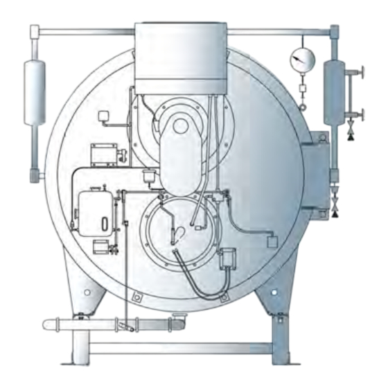
All “CB” boilers have the burner assembly attached to the front head. The entire head may be swung open for inspection and maintenance. - Page 16 General Description FIGURE 1-1. Typical Steam Boiler - Light Oil Fired FIGURE 1-2. Typical Hot Water Boiler 750-96 (revised 2010) Model CB Packaged Boiler Manual...
- Page 17 It must be manually reset following a safety shutdown caused by a loss of flame. Incorporated is an internal checking circuit, effective on every start, that will prevent burner operation in the event anything causes the flame relay to hold in during this period. 750-96 (revised 2010) Model CB Packaged Boiler Manual...
- Page 18 The inner is rotated, under control of the modulating motor, to vary the effec- tive size of the openings where they overlap. Courtesy of: C3 Surplus LLC Surplus Industrial Superstore 305-428-2777 https://www.c3surplus.com 750-96 (revised 2010) Model CB Packaged Boiler Manual...
-
Page 19: Steam Controls: All Fuels
Safety valves and their escape piping are to be installed to conform to the ASME Code requirements. NOTE: Only the safety valves manufacturer’s representative should adjust or repair the boiler safety valves. 750-96 (revised 2010) Model CB Packaged Boiler Manual... -
Page 20: Hot Water Controls: All Fuels
3. Gas Pilot Shutoff For manually opening or closing the gas supply to the gas pilot valve. Cock 4. Gas Pilot Adjusting Provided to regulate the size of the gas pilot flame. Cock 750-96 (revised 2010) Model CB Packaged Boiler Manual... - Page 21 The body of the gas valve has a plugged opening that is used whenever it is necessary or desirous to conduct a test for possible leakage across the closed valve. Courtesy of: C3 Surplus LLC Surplus Industrial Superstore 305-428-2777 https://www.c3surplus.com 750-96 (revised 2010) Model CB Packaged Boiler Manual...
- Page 22 General Description FIGURE 1-3. Gas Train (configurations may vary) FIGURE 1-4. Oil Control Valve Assembly: For Light Oil 1-10 750-96 (revised 2010) Model CB Packaged Boiler Manual...
-
Page 23: Controls Common To Oil Fired Boilers (Including Combination)
Prevents lubricating oil and compressed air from surging back through the pump and air filter when the pump stops. 8. Air-Oil Receiver Tank Holds supply of oil for lubricating the air pump. Separates lube oil from atomizing air before delivery to the nozzle. 1-11 750-96 (revised 2010) Model CB Packaged Boiler Manual... - Page 24 A restriction located in the oil return line immediately downstream of the fuel oil control- fice ler to create back pressure (100 and 200 series only). Courtesy of: C3 Surplus LLC Surplus Industrial Superstore 305-428-2777 https://www.c3surplus.com 1-12 750-96 (revised 2010) Model CB Packaged Boiler Manual...
-
Page 25: Additional Controls For Heavy Oil (No. 4, 5, And 6)
Switch contacts open when fuel oil temperature raises above a selected temperature. ture Switch (optional) Switch will interrupt the limit circuit in the event fuel oil temperature rises above the selected point. 1-13 750-96 (revised 2010) Model CB Packaged Boiler Manual... -
Page 26: Controls For Combination Burners Only
Chapter 4 details the required mechanical functions of each fuel system. Courtesy of: C3 Surplus LLC Surplus Industrial Superstore 305-428-2777 https://www.c3surplus.com 1-14 750-96 (revised 2010) Model CB Packaged Boiler Manual... -
Page 27: Combustion Air
A series 100 burner usually is equipped with a pilot fired with light oil fuel. All other burners, as well as a series 100 burner complying with insurance underwriters requirements, are equipped with a gas burning pilot. In the 1-15 750-96 (revised 2010) Model CB Packaged Boiler Manual... -
Page 28: Atomizing Air
The fuel oil controller contains in a single unit, a metering valve, a regulator, and a gauge required to regulate the pressure and flow of oil to the burner. The adjustable regulator controls the pressure. To 1-16 750-96 (revised 2010) Model CB Packaged Boiler Manual... - Page 29 FIGURE 1-7. Light Oil Flow Diagram 1-17 750-96 (revised 2010) Model CB Packaged Boiler Manual...
-
Page 30: Oil Fuel Flow: Heavy Oil
This assures a clean nozzle and line for the subsequent restart. (Purging is not provided on No. 4 oil.) Courtesy of: C3 Surplus LLC Surplus Industrial Superstore 305-428-2777 https://www.c3surplus.com 1-18 750-96 (revised 2010) Model CB Packaged Boiler Manual... - Page 31 1.16 — Oil Fuel Flow: Heavy Oil FIGURE 1-8. Heavy Oil Flow Diagram (Steam-Electric Heater 1-19 750-96 (revised 2010) Model CB Packaged Boiler Manual...
- Page 32 General Description FIGURE 1-9. No. 4 Heavy Oil Flow Diagram Courtesy of: C3 Surplus LLC Surplus Industrial Superstore 305-428-2777 https://www.c3surplus.com 1-20 750-96 (revised 2010) Model CB Packaged Boiler Manual...
- Page 33 1.16 — Oil Fuel Flow: Heavy Oil FIGURE 1-10. No. 5 Heavy Oil Flow Diagram 1-21 750-96 (revised 2010) Model CB Packaged Boiler Manual...
-
Page 34: Gas Fuel Flow
Rotation in either direction continues until the resistance ratio of the two potentiometers is equal. When this occurs, the motor stops in a position that allows the proper fuel and combustion air flow to meet oper- ating demands. 1-22 750-96 (revised 2010) Model CB Packaged Boiler Manual... - Page 35 This switch closes, as high fire position is approached, to complete an internal circuit in the programmer and allow continuation of the programming cycle. Courtesy of: C3 Surplus LLC Surplus Industrial Superstore 305-428-2777 https://www.c3surplus.com 1-23 750-96 (revised 2010) Model CB Packaged Boiler Manual...
- Page 36 General Description Courtesy of: C3 Surplus LLC Surplus Industrial Superstore 305-428-2777 https://www.c3surplus.com 1-24 750-96 (revised 2010) Model CB Packaged Boiler Manual...
-
Page 37: The Pressure Vessel
Heating Boiler Code. For water temperatures between 240º - 250º F, minimum design pressure is 60 psig, but because of static the head may be as high as 160 psig and constructed to Section IV of Low Pressure Heating Boiler Code. 750-96 (revised 2010) Model CB Packaged Boiler Manual... -
Page 38: Water Requirements
The relief device or bypass valve will thus allow continuous circulation through the boiler and can help prevent rapid replacement of boiler water with “cold” zone water. 750-96 (revised 2010) Model CB Packaged Boiler Manual... -
Page 39: Continuous Flow Through The Boiler
This can best be accomplished by use of balancing cocks and gauges in the supply line from each boiler. If balancing cocks or orifice plates are used, a significant pressure drop (e.g., 3-5 psi) must be taken across the balancing device to accomplish this purpose. 750-96 (revised 2010) Model CB Packaged Boiler Manual... -
Page 40: Pressure Drop Through Boiler
It cannot be over-emphasized that rapid changes in temperature within the boiler can, and sometimes do, cause damage. Courtesy of: C3 Surplus LLC Surplus Industrial Superstore 305-428-2777 https://www.c3surplus.com 750-96 (revised 2010) Model CB Packaged Boiler Manual... -
Page 41: Steam Boiler
The water feeder should close when water reaches the proper level as shown in Figure 2-3. Courtesy of: C3 Surplus LLC Surplus Industrial Superstore 305-428-2777 https://www.c3surplus.com 750-96 (revised 2010) Model CB Packaged Boiler Manual... -
Page 42: Water Treatment
The internal or waterside surfaces of the pressure vessel should be inspected with sufficient frequency to deter- mine the presence of any contamination, accumulations of foreign matter, of corrosion and/or pitting. If these con- 750-96 (revised 2010) Model CB Packaged Boiler Manual... -
Page 43: Cleaning
Inspection should be made three months after initial starting and at regular 6-, 9-, or 12-month intervals thereafter. The frequency of further periodic inspections will depend upon the internal conditions found. 750-96 (revised 2010) Model CB Packaged Boiler Manual... -
Page 44: Boil-Out Of A New Unit
Boiler Model and Water - Gallons Water - Weight Size Normal Flooded Normal Flooded CB50 3125 3665 2920 3500 CB60 CB70 4625 5420 CB80 4460 5250 5085 5960 CB100 CB100A 4960 CB1025A 5585 750-96 (revised 2010) Model CB Packaged Boiler Manual... - Page 45 On a hot water system, chemical cleaning is generally necessary and the entire system should be drained after treatment. Consult water treatment companies for recommendations, cleaning, compounds, and application pro- cedures. Courtesy of: C3 Surplus LLC Surplus Industrial Superstore 305-428-2777 https://www.c3surplus.com 750-96 (revised 2010) Model CB Packaged Boiler Manual...
-
Page 46: Washing Out
Scale has a low heat transfer value and acts as an insulation barrier. This retards heat transfer, which not only results in lower operating efficiency and consequently higher fuel consumption, but more importantly, can cause 2-10 750-96 (revised 2010) Model CB Packaged Boiler Manual... -
Page 47: Manual Blowdown
The continuous blowdown removes sediment and oil from the surface of the water along with a prescribed amount of dissolved solids. When surface or continuous blowdown is not utilized, manual blowdown is used to control the dissolved or sus- pended solids in addition to the sludge. 2-11 750-96 (revised 2010) Model CB Packaged Boiler Manual... -
Page 48: Manual Blowdown Procedure
Close the downstream (slow opening) valve first and as fast as possible. Then close the valve next to the boiler. Slightly crack the downstream valve and then close it tightly. 2-12 750-96 (revised 2010) Model CB Packaged Boiler Manual... -
Page 49: Periodic Inspection
Also check and clean drain and blowdown valves and piping. Check all water and steam piping and valves for leaks, wear, corrosion, and other damage. Replace or repair as required. Courtesy of: C3 Surplus LLC Surplus Industrial Superstore 305-428-2777 https://www.c3surplus.com 2-13 750-96 (revised 2010) Model CB Packaged Boiler Manual... -
Page 50: Preparation For Extended Layup
Internal water pressure should be maintained at greater than atmospheric pres- sure. Nitrogen is often used to pressurize the vessel. Fireside surfaces must be thoroughly cleaned and the refrac- tory should be wash coated. 2-14 750-96 (revised 2010) Model CB Packaged Boiler Manual... -
Page 51: Sequence Of Operation
• The load demand light glows. All entrance switches are closed and power is present at the line terminals of: • Blower motor starter • Air compressor motor starter (if provided) • Oil heater relay (if provided) 750-96 (revised 2010) Model CB Packaged Boiler Manual... -
Page 52: Circuit And Interlock Controls
Atomizing air proving switch (AAPS) • Low Fire Proving Circuit Low fire switch (LFS) • Pilot Ignition Circuit Gas pilot valve (GPV) • Ignition transformer (IT) • Gas pilot vent valve (GPVV), if provided • 750-96 (revised 2010) Model CB Packaged Boiler Manual... -
Page 53: Sequence Of Operation: Oil Or Gas
On certain boilers the circuitry will include a high fire switch (HFS). The purpose of this switch is to prove that the modulating damper motor (MDM) has driven the damper to the open position during the pre-purge cycle. In this instance, the “high fire proving circuit” is utilized. 750-96 (revised 2010) Model CB Packaged Boiler Manual... -
Page 54: Ignition Cycle
(MFC) or the modulating control (MC) depending upon the position of the manual-automatic switch (MAS). This allows operation in ranges above low fire. 750-96 (revised 2010) Model CB Packaged Boiler Manual... -
Page 55: Burner Shutdown Post Purge
Lockout will also occur if flame or flame simulating condition occurs during the pre-purge period. Courtesy of: C3 Surplus LLC Surplus Industrial Superstore 305-428-2777 https://www.c3surplus.com 750-96 (revised 2010) Model CB Packaged Boiler Manual... -
Page 56: No Pilot Flame
Knowledge of the system and its controls will make troubleshooting much easier in the event it is necessary. Costly downtime 750-96 (revised 2010) Model CB Packaged Boiler Manual... - Page 57 Courtesy of: C3 Surplus LLC Surplus Industrial Superstore 305-428-2777 https://www.c3surplus.com 750-96 (revised 2010) Model CB Packaged Boiler Manual...
- Page 58 Sequence of Operation Courtesy of: C3 Surplus LLC Surplus Industrial Superstore 305-428-2777 https://www.c3surplus.com 750-96 (revised 2010) Model CB Packaged Boiler Manual...
-
Page 59: Starting And Operating Instructions
Check for rotation of all motors by momentarily closing the motor starter or relay. Blower impeller rotation is coun- terclockwise when viewed from front of boiler. Air pump rotation is clockwise when viewed from its drive end. 750-96 (revised 2010) Model CB Packaged Boiler Manual... -
Page 60: Control Settings: Steam And Hot Water
In the event the boiler is equipped with optional control devices not listed here, be certain to ascertain that their settings are correct. If additional information is required, see your Cleaver-Brooks representative. 750-96 (revised 2010) Model CB Packaged Boiler Manual... -
Page 61: Gas Pilot
In this event, check the nozzle and clean as necessary. After air flow has been verified, turn the burner switch off and return the run/test switch to the “run” position. 750-96 (revised 2010) Model CB Packaged Boiler Manual... -
Page 62: Firing Preparations For No. 2 Oil: Series 100-200
Non-lubricating fluids such as kerosene should not be used for priming. Prior to priming the suction line and the initial start, check to make certain that all plugs, connections, etc., have been securely tightened to prevent leaks. 750-96 (revised 2010) Model CB Packaged Boiler Manual... -
Page 63: Oil Pressure
When all the conditions covered above and in Sections 4.1, 4.2, 4.3, and 4.4 are assured, the burner is ready for firing. Refer to Section 4.8 of this chapter for further starting and operating information. 750-96 (revised 2010) Model CB Packaged Boiler Manual... -
Page 64: Firing Preparations For No. 4 Oil: Series 800-900
The electric oil heater has a built in adjustable thermostat. The normal temperature requirement is 100º F. Should adjustment be necessary, turn the adjusting screw and use the thermometer in the fuel oil controller as a guide to the proper temperature. 750-96 (revised 2010) Model CB Packaged Boiler Manual... -
Page 65: Oil Flow
The pressure reducing valve on the fuel oil controller should be adjusted if necessary to obtain a pressure reading on the controller oil gauge of approximately 40-50 psi. After the burner is firing and with properly heated oil, further adjustments can be made, if necessary, to these valves. 750-96 (revised 2010) Model CB Packaged Boiler Manual... -
Page 66: Oil Flow
Open all valves in the oil suction and oil return lines. Open the bypass valve on the fuel oil controller until oil flow is established. Normally, the orifice valve is left in a closed position. However, on cold starts, it may be opened for 750-96 (revised 2010) Model CB Packaged Boiler Manual... -
Page 67: Oil Pressure
After determining that the heater shell is filled and that fuel oil circulation exists, turn the oil heater switch to “on.” Adjust the electric oil heater thermostat to maintain oil temperature at approximately 200º F. Courtesy of: C3 Surplus LLC Surplus Industrial Superstore 305-428-2777 https://www.c3surplus.com 750-96 (revised 2010) Model CB Packaged Boiler Manual... -
Page 68: Starting
Determine that the pilot is operating properly as outlined in Section 4.3 4-10 750-96 (revised 2010) Model CB Packaged Boiler Manual... - Page 69 When the conditions covered above and in Sections 4.1, 4.2, and 4.3 are assured, the burner is ready for firing. Refer to Section 4.10 for further starting and operating information. Courtesy of: C3 Surplus LLC Surplus Industrial Superstore 305-428-2777 https://www.c3surplus.com 4-11 750-96 (revised 2010) Model CB Packaged Boiler Manual...
- Page 70 5. After making the high fire adjustment manually, position the burner over the range from high to low fire, stop- ping at intermediate points, analyzing combustion gases, and adjusting as required. 4-12 750-96 (revised 2010) Model CB Packaged Boiler Manual...
- Page 71 It is advisable to check for tight shutoff of fuel valves. Despite precautions and strainers, foreign material in either new or renovated fuel lines may lodge under a valve seat preventing tight closure. This is especially true in new installa- tions. Promptly correct any conditions causing leakage. 4-13 750-96 (revised 2010) Model CB Packaged Boiler Manual...
-
Page 72: Control Operational Test And Checks
Promptly correct any conditions causing leakage. Refer to adjustment procedures and maintenance instructions give in Chapters 5 and 7. Courtesy of: C3 Surplus LLC Surplus Industrial Superstore 305-428-2777 https://www.c3surplus.com 4-14 750-96 (revised 2010) Model CB Packaged Boiler Manual... -
Page 73: Adjustment Procedures
• Initial adjustment should be made with the motor in full closed position, that is with the shaft on the power end of the motor in its most counterclockwise position. 750-96 (revised 2010) Model CB Packaged Boiler Manual... - Page 74 With the modulating motor in the low fire position, the arm on its shaft should be at an angle of 45º below the hor- izontal. The driven arm on the jackshaft should be parallel to this. Secure both arms and fit the connecting linkage rod in place between them. 750-96 (revised 2010) Model CB Packaged Boiler Manual...
- Page 75 Normally, the rate of flow of air through the damper with the rotor in low fire posi- tion is about one-third of maximum. Rotary Air Damper FIGURE 5-3. 750-96 (revised 2010) Model CB Packaged Boiler Manual...
-
Page 76: Modulating Motor: Honeywell M954B Or M954C
60º on motor opening. Normally, these settings are left as is but job conditions may require readjustment. If the cams require adjustment or resetting, follow the instructions in the manufacturer’s Technical Bulletin. Courtesy of: C3 Surplus LLC Surplus Industrial Superstore 305-428-2777 https://www.c3surplus.com 750-96 (revised 2010) Model CB Packaged Boiler Manual... -
Page 77: Burner Operating Controls: General
Please note that this is not drawn to any scale. The burner will be “on” whenever the pressure or temperature is below point B and “off” whenever pressure or temperature is above point A. The distance between points A and B represents the “on-off” differential of the operating limit control. 750-96 (revised 2010) Model CB Packaged Boiler Manual... - Page 78 This fixed differential range is described later in this section. The scale setting of the modulating temperature con- 750-96 (revised 2010) Model CB Packaged Boiler Manual...
- Page 79 NOTE: To prevent burner shutdown at other than low fire setting, adjust the modulat- ing temperature control to modulate to low fire BEFORE the operating limit tempera- ture control shuts off the burner. 750-96 (revised 2010) Model CB Packaged Boiler Manual...
- Page 80 No adjustment is required since these controls are preset by the original manufac- Devices: Steam and Hot turer. However, if water level is not maintained, inspect devices immediately and Water replace as required. Courtesy of: C3 Surplus LLC Surplus Industrial Superstore 305-428-2777 https://www.c3surplus.com 750-96 (revised 2010) Model CB Packaged Boiler Manual...
-
Page 81: Gas Pilot Flame Adjustment
The flame must be sufficient to ignite the main flame and to be seen by the flame detector but an extremely large flame is not required. An overly rich flame can cause sooting of the flame detector. Too small a flame can cause ignition problems. 750-96 (revised 2010) Model CB Packaged Boiler Manual... - Page 82 See the flame signal table in the manufacturer’s bulletin for values of other combina- tions. The flame signal indicated on the annunciator type relay should not be less than 10 volts D.C. and may be as high as 20 or greater. 5-10 750-96 (revised 2010) Model CB Packaged Boiler Manual...
-
Page 83: Gas Pressure And Flow Information
Minimum Net Regulated Gas Pressure for Rated Boiler Output (Required at Gas Train Entrance) TABLE 1. Standard and FM Approved Boiler Size (H.P.) Train IRI Approved Train 11.0 10.5 100A 10.5 100S 11.5 125A 12.0 12.0 5-11 750-96 (revised 2010) Model CB Packaged Boiler Manual... -
Page 84: Gas Flow
“base” pressure. 5-12 750-96 (revised 2010) Model CB Packaged Boiler Manual... - Page 85 (Table 3) and “correct this answer by applying the correction factor for 3 psig (Table 4). BTU/hr Input = CFH (Cubic Feet/Hour) BTU/cu. ft. 4,184,000 = 4,184 CFH 1,000 (at 14.7 lb. atmospheric “base” pressure) 5-13 750-96 (revised 2010) Model CB Packaged Boiler Manual...
-
Page 86: Gas Fuel Combustion Adjustment
Calculate the actual pressure and flow through the use of correction factors that compensate for incoming gas pressure and altitude. Courtesy of: C3 Surplus LLC Surplus Industrial Superstore 305-428-2777 https://www.c3surplus.com 5-14 750-96 (revised 2010) Model CB Packaged Boiler Manual... - Page 87 If corrections are necessary, increase or decrease the gas pressure by adjusting the gas pressure regulator, fol- lowing manufacturer’s directions for regulator adjustment. 5-15 750-96 (revised 2010) Model CB Packaged Boiler Manual...
- Page 88 (counterclockwise from the hex-socket end) to increase the flow of fuel, and in (clockwise from the hex-socket end) to decrease it. Flow rate is highest when the cam follower assembly is closest to the jackshaft. 5-16 750-96 (revised 2010) Model CB Packaged Boiler Manual...
-
Page 89: Low Gas Pressure Switch
The Oil Viscos- ity Chart (Figure 5-7) may be used as a guide, although your oil supplier will be able to give you more exacting information based on an analysis of the oil. 5-17 750-96 (revised 2010) Model CB Packaged Boiler Manual... -
Page 90: Fuel Oil Combustion Adjustment
5.12 — Fuel Oil Combustion Adjustment After operating for a sufficient period of time to assure a warm boiler, adjustments should be made to obtain effi- cient combustion. 5-18 750-96 (revised 2010) Model CB Packaged Boiler Manual... - Page 91 Repeat as necessary until the desired flow is obtained. NOTE: Do not use any lubricant on the adjusting setscrews. These have a nylon locking insert intended to provide lock- ing torque and resistance to loosening. 5-19 750-96 (revised 2010) Model CB Packaged Boiler Manual...
-
Page 92: Burner Drawer Adjustment
1/8” beyond this plate. Locate the nozzle approxi- mately 3/8” behind the diffuser on CB100, CB100A, and CB125A boilers. Courtesy of: C3 Surplus LLC Surplus Industrial Superstore 305-428-2777 https://www.c3surplus.com 5-20 750-96 (revised 2010) Model CB Packaged Boiler Manual... -
Page 93: Oil Drawer Switch
Adjustment of the switch must be such that its contacts open if the oil drawer is not properly positioned for oil firing. The switch is electrically removed from the circuit when a combination fuel burner is fired on gas. Courtesy of: C3 Surplus LLC Surplus Industrial Superstore 305-428-2777 https://www.c3surplus.com 5-21 750-96 (revised 2010) Model CB Packaged Boiler Manual... -
Page 94: Low Oil Temperature Switch
The electric heater is sized to provide sufficient heated oil for low fire operation on cold starts before steam is available. A 0.005 MFD capacitor is wired in parallel with the thermostat lead connections to prevent contact bounce and arcing. The control differential is non-adjustable. 5-22 750-96 (revised 2010) Model CB Packaged Boiler Manual... - Page 95 This regulator is provided on a boiler designed to operate at pressures above 15 psi for the purpose of reducing boiler steam pressure to the level necessary for proper operation of the steam oil heater. This pressure should be 5-23 750-96 (revised 2010) Model CB Packaged Boiler Manual...
- Page 96 Courtesy of: C3 Surplus LLC Surplus Industrial Superstore 305-428-2777 https://www.c3surplus.com 5-24 750-96 (revised 2010) Model CB Packaged Boiler Manual...
-
Page 97: Troubleshooting
Familiarity with the programmer and other controls in the system may be obtained by studying the contents of this manual and the bulletin. Knowledge of the system and its controls will make troubleshooting much easier. 750-96 (revised 2010) Model CB Packaged Boiler Manual... - Page 98 E. Heavy oil fired unit - oil temperature below minimum settings. Fuel valve interlock circuit not completed. A. Fuel valve auxiliary switch not enclosed. Courtesy of: C3 Surplus LLC Surplus Industrial Superstore 305-428-2777 https://www.c3surplus.com 750-96 (revised 2010) Model CB Packaged Boiler Manual...
- Page 99 Insufficient or no voltage at main fuel valve circuit terminal. BURNER STAYS IN LOW- Pressure or temperature above modulating control setting. FIRE Manual-automatic switch in wrong position. Inoperative modulating motor. Defective modulating control. Binding or loose linkage, cams, setscrews, etc. 750-96 (revised 2010) Model CB Packaged Boiler Manual...
- Page 100 A. Manual-automatic switch in wrong position. B. Modulating control improperly set or inoperative. C. Motor defective. D. Loose electrical connection. E.Damper motor transformer defective. Courtesy of: C3 Surplus LLC Surplus Industrial Superstore 305-428-2777 https://www.c3surplus.com 750-96 (revised 2010) Model CB Packaged Boiler Manual...
-
Page 101: Inspection And Maintenance
7.1.1 — Periodic Inspection Insurance regulations or local laws require a periodic inspection of the pressure vessel by an authorized inspector. Section 2.1 in Chapter 2 contains information relative to this inspection. 750-96 (revised 2010) Model CB Packaged Boiler Manual... -
Page 102: Fireside Cleaning
The need to periodically check water level controls and the waterside of the pressure vessel cannot be over- emphasized. Most instances of major boiler damage are the result of operating with low water or the use of untreated or incorrectly teated water. 750-96 (revised 2010) Model CB Packaged Boiler Manual... - Page 103 750-96 (revised 2010) Model CB Packaged Boiler Manual...
-
Page 104: Water Gauge Glass
The power supply to the boiler must be protected with dual element fuses (fusetrons) or circuit breakers. Similar fuses should be used in branch circuits and standard one-shot fuses are not recommended. Information given on the Fuse Sizes Chart (Figure 7-2) is included for guidance to fuse requirements. 750-96 (revised 2010) Model CB Packaged Boiler Manual... -
Page 105: Program And Flame Safety Control
(e.g., seasonal), the active control should be removed and stored. Moisture can cause problems. It is recommended that service be rotated between the active and a spare control to assure having a working replacement. 750-96 (revised 2010) Model CB Packaged Boiler Manual... -
Page 106: Checking Pilot Flame Failure
Turn the burner switch off. Reset the safety switch. Re-establish main fuel supply. The flame detector lens should be cleaned as often as operating conditions demand. Use a soft cloth moistened with detergent. Courtesy of: C3 Surplus LLC Surplus Industrial Superstore 305-428-2777 https://www.c3surplus.com 750-96 (revised 2010) Model CB Packaged Boiler Manual... -
Page 107: Oil Burner Maintenance
To disassemble, unlatch and withdraw the burner gun. Insert the nozzle body into the hanger vice and use the spanner wrench to remove the tip. Carefully remove the swirler and seating spring being careful not to drop or damage any parts. 750-96 (revised 2010) Model CB Packaged Boiler Manual... -
Page 108: Air Purge Nozzle (No. 6 Oil), Back Pressure Orifice Nozzle (No. 2 Oil)
Inspect the electrode tip for signs of pitting or combustion deposits and dress as required with a fine file. Inspect the porcelain insulator for any cracks that might be present. If there are, replace the electrode since it can cause 750-96 (revised 2010) Model CB Packaged Boiler Manual... -
Page 109: Gas Burner Maintenance
• Yellow = shut • Red = open The auxiliary switch normally used as a valve closed indication switch is replaceable as a component. Courtesy of: C3 Surplus LLC Surplus Industrial Superstore 305-428-2777 https://www.c3surplus.com 750-96 (revised 2010) Model CB Packaged Boiler Manual... -
Page 110: Solenoid Valves
After connecting the motor leads, check the rotation of the impeller to be sure that it is counterclockwise when viewed from the motor end. 7-10 750-96 (revised 2010) Model CB Packaged Boiler Manual... -
Page 111: Safety Valves
Code required drains can be properly piped to prevent buildup of back pressure and accumulation of foreign material around the valve seat area. Apply only a moderate amount of pipe compound to male threads and avoid 7-11 750-96 (revised 2010) Model CB Packaged Boiler Manual... -
Page 112: Fuel Oil Metering Valve, Adjusting And Relief Valves
Match mark the cam hub and drive shaft. This will enable replacement of the cam in its original position and result in a minimum of cam adjustment when the burner is refired. Clamp or hold the metering stem in the down position. 7-12 750-96 (revised 2010) Model CB Packaged Boiler Manual... - Page 113 Clean the slotted stem of the oil metering valve with suitable solvent and blow dry with an air line. Follow the above procedure when removing or reinstalling the metering valve stem. Also check all fuel line strainers. 7-13 750-96 (revised 2010) Model CB Packaged Boiler Manual...
-
Page 114: Air Pump And Lubricating System
Remove the cover from the fill pipe and add oil through the conical strainer in this pipe with the unit running. Oil must never be added unless the pump is in operation and the strainer screen in place. 7-14 750-96 (revised 2010) Model CB Packaged Boiler Manual... -
Page 115: Lubricating Oil Strainer And Cooling Coil
Be sure to fit the o-ring gasket under the cover so that a tight seal is obtained. Air-Oil Tank FIGURE 7-7. 7-15 750-96 (revised 2010) Model CB Packaged Boiler Manual... -
Page 116: Lube Oil Cooling Coil
The coupling will then have proper angular alignment. Remember that alignment in one direction may alter the alignment in another. Recheck thoroughly both angular and parallel alignment procedures after making any alterations. 7-16 750-96 (revised 2010) Model CB Packaged Boiler Manual... -
Page 117: Air Pump Replacement
When replacing the retainer screen, a slight force may be required to push the cooling coil into the air cylinder so that pins may be fitted into place. Make sure that all piping connections are tight. 7-17 750-96 (revised 2010) Model CB Packaged Boiler Manual... -
Page 118: Refractory
Thin joints are desirable. Generally, it will be necessary to shave a portion from one or more tile to obtain a fit. If a fill piece is required, cut it to fit and install this piece at the bottom of the furnace. 7-18 750-96 (revised 2010) Model CB Packaged Boiler Manual... -
Page 119: Rear Door
• The air line to the rear sight tube may be blocked or loose. • Repainted with other than heat resistant paint. Therefore, before assuming the refractory requires reworking: • Check condition of tadpole gasket and rope seal. 7-19 750-96 (revised 2010) Model CB Packaged Boiler Manual... -
Page 120: Front Inner Door
Inspect the retaining pins and replace if necessary. Reinforcing wire suitably attached may also be used. The recommended insulation is known as Vee Block Mix and is available in 50 lb. bags (CB part num- ber 872-162). -
Page 121: Opening And Closing Rear Head
Attach a new length of 1-1/4” diameter fiberglass rope (P/N 853-982) to the baffle. Be certain that it is properly positioned and use a rapid setting adhesive (P/N 872-481) to hold it in place. 7-21 750-96 (revised 2010) Model CB Packaged Boiler Manual... -
Page 122: Closing And Sealing
Before replacing the drain plug, run the motor for 10 to 20 minutes to expel any excess grease. The filler and drain plugs should be thoroughly cleaned before they are replaced. 7-22 750-96 (revised 2010) Model CB Packaged Boiler Manual... -
Page 123: Control Linkage
A 50/50 solution of permanent anti-freeze and water is generally used as the heat transfer solution, although if there is no danger of freezing, plain water may be used as a replenishment if necessary to refill. Courtesy of: C3 Surplus LLC Surplus Industrial Superstore 305-428-2777 https://www.c3surplus.com 7-23 750-96 (revised 2010) Model CB Packaged Boiler Manual... - Page 124 Circulation Layout of Hot Water Oil Heater (Alstrom) FIGURE 7-11. Evidence of oil in either the steam heater condensate or in the water heater indicator demands prompt repairs. Courtesy of: C3 Surplus LLC Surplus Industrial Superstore 305-428-2777 https://www.c3surplus.com 7-24 750-96 (revised 2010) Model CB Packaged Boiler Manual...
-
Page 125: Ordering Parts And Parts Lists
If repair parts are required for accessory equipment, such as an electric motor, pump, etc., which may not be shown, be sure to give the complete name plate data from the item for which the parts are required. 750-96 (revised 2010) Model CB Packaged Boiler Manual... -
Page 126: Where To Order Parts
Consult your Cleaver-Brooks representative or Cleaver-Brooks for information and prices. Be sure to show the serial number of your boiler on all parts orders and correspondence. Courtesy of: C3 Surplus LLC Surplus Industrial Superstore 305-428-2777 https://www.c3surplus.com 750-96 (revised 2010) Model CB Packaged Boiler Manual... -
Page 127: Parts Lists
8.2 — Parts Lists 8.2 — Parts Lists 8.2.1 — Rear Head Sealing Courtesy of: C3 Surplus LLC Surplus Industrial Superstore 305-428-2777 https://www.c3surplus.com 750-96 (revised 2010) Model CB Packaged Boiler Manual... -
Page 128: Rear Head Sealing - Davit
Ordering Parts and Parts Lists 8.2.2 — Rear Head Sealing - Davit 750-96 (revised 2010) Model CB Packaged Boiler Manual... -
Page 129: Fireside Gasket
8.2 — Parts Lists 8.2.3 — Fireside Gasket 750-96 (revised 2010) Model CB Packaged Boiler Manual... -
Page 130: Front Head Electrical
Ordering Parts and Parts Lists 8.2.4 — Front Head Electrical 750-96 (revised 2010) Model CB Packaged Boiler Manual... -
Page 131: Lwco Water Column Piping, 30 - 125# Mdm
8.2 — Parts Lists 8.2.5 — LWCO Water Column Piping, 30 - 125# MDM Courtesy of: C3 Surplus LLC Surplus Industrial Superstore 305-428-2777 https://www.c3surplus.com 750-96 (revised 2010) Model CB Packaged Boiler Manual... -
Page 132: Lwco Water Column Piping, 15# Mdm
Ordering Parts and Parts Lists 8.2.6 — LWCO Water Column Piping, 15# MDM 750-96 (revised 2010) Model CB Packaged Boiler Manual... -
Page 133: Lwco Water Column Piping, 150# Mdm
8.2 — Parts Lists 8.2.7 — LWCO Water Column Piping, 150# MDM 750-96 (revised 2010) Model CB Packaged Boiler Manual... -
Page 134: Lwco Water Column Piping, 15# Level Master
Ordering Parts and Parts Lists 8.2.8 — LWCO Water Column Piping, 15# Level Master 8-10 750-96 (revised 2010) Model CB Packaged Boiler Manual... -
Page 135: Lwco Water Column Piping, 150# Level Master
8.2 — Parts Lists 8.2.9 — LWCO Water Column Piping, 150# Level Master 8-11 750-96 (revised 2010) Model CB Packaged Boiler Manual... -
Page 136: Entrance Box
Ordering Parts and Parts Lists 8.2.10 — Entrance Box 8-12 750-96 (revised 2010) Model CB Packaged Boiler Manual... -
Page 137: Control Panel
8.2 — Parts Lists 8.2.11 — Control Panel Courtesy of: C3 Surplus LLC Surplus Industrial Superstore 305-428-2777 https://www.c3surplus.com 8-13 750-96 (revised 2010) Model CB Packaged Boiler Manual... - Page 138 Ordering Parts and Parts Lists Courtesy of: C3 Surplus LLC Surplus Industrial Superstore 305-428-2777 https://www.c3surplus.com 8-14 750-96 (revised 2010) Model CB Packaged Boiler Manual...
-
Page 139: Furnace Liner & Bricking
8.2 — Parts Lists 8.2.12 — Furnace Liner & Bricking Courtesy of: C3 Surplus LLC Surplus Industrial Superstore 305-428-2777 https://www.c3surplus.com 8-15 750-96 (revised 2010) Model CB Packaged Boiler Manual... -
Page 140: Front Head Linkage
Ordering Parts and Parts Lists 8.2.13 — Front Head Linkage 8-16 750-96 (revised 2010) Model CB Packaged Boiler Manual... -
Page 141: Temperature Controls
8.2 — Parts Lists 8.2.14 — Temperature Controls 8-17 750-96 (revised 2010) Model CB Packaged Boiler Manual... -
Page 142: Gas Piping
Ordering Parts and Parts Lists 8.2.15 — Gas Piping 8-18 750-96 (revised 2010) Model CB Packaged Boiler Manual... -
Page 143: L.o. Front Head Oil/Air Piping
8.2 — Parts Lists 8.2.16 — L.O. Front Head Oil/Air Piping 8-19 750-96 (revised 2010) Model CB Packaged Boiler Manual... -
Page 144: H.o. Front Head Oil/Air Piping
Ordering Parts and Parts Lists 8.2.17 — H.O. Front Head Oil/Air Piping 8-20 750-96 (revised 2010) Model CB Packaged Boiler Manual... -
Page 145: Steam Electric Heater
8.2 — Parts Lists 8.2.18 — Steam Electric Heater Courtesy of: C3 Surplus LLC Surplus Industrial Superstore 305-428-2777 https://www.c3surplus.com 8-21 750-96 (revised 2010) Model CB Packaged Boiler Manual... - Page 146 Ordering Parts and Parts Lists Courtesy of: C3 Surplus LLC Surplus Industrial Superstore 305-428-2777 https://www.c3surplus.com 8-22 750-96 (revised 2010) Model CB Packaged Boiler Manual...
Need help?
Do you have a question about the CB and is the answer not in the manual?
Questions and answers