Table of Contents
Advertisement
Quick Links
Advertisement
Table of Contents

Related Manuals for CleaverBrooks CBEX-DE


Summary of Contents for CleaverBrooks CBEX-DE
- Page 1 CBEX-DE Dryback Elite Boiler 250-800 HP Operation and Maintenance 750-392 10/2019...
- Page 2 ! DANGER WARNING DO NOT OPERATE, SERVICE, OR REPAIR THIS EQUIPMENT UNLESS YOU FULLY UNDERSTAND ALL APPLICABLE SECTIONS OF THIS MANUAL. DO NOT ALLOW OTHERS TO OPERATE, SERVICE, OR REPAIR THIS EQUIPMENT UNLESS THEY FULLY UNDERSTAND ALL APPLICABLE SECTIONS OF THIS MANUAL. FAILURE TO FOLLOW ALL APPLICABLE WARNINGS AND INSTRUCTIONS MAY RESULT IN SEVERE PERSONAL INJURY OR DEATH.
-
Page 3: Table Of Contents
CONTENTS Introduction 1-1 CHAPTER 1 Overview 1-1 Component Locations 1-3 Waterside Care 2-1 CHAPTER 2 Water requirements - steam boilers 2-1 Water requirements - hot water boilers 2-2 Water Treatment 2-4 Cleaning 2-5 Boil-Out of a New Unit 2-6 Washing Out 2-8 Blowdown - Steam Boilers 2-9 Periodic Inspection 2-12 Preparation for Extended Layup 2-13... - Page 4 Inspection and Maintenance 5-1 CHAPTER 5 Periodic Inspection 5-2 Fireside Cleaning 5-3 Water Level Controls 5-3 Water Gauge Glass 5-4 Electrical Controls 5-5 Flame Safety Control 5-5 Removing Burner Drawer 5-7 Oil Burner Maintenance 5-7 Gas Burner Maintenance 5-9 Motorized Gas Valve 5-10 Solenoid Valves 5-10 Air Control Damper 5-10 Fan/Motor Cassette Removal 5-11...
-
Page 5: Introduction
CHAPTER 1 1.1 — Overview The CBEX-DE boiler is a packaged firetube boiler of welded steel construction and consists of a pressure vessel, burner, burner controls, forced draft fan, air compressor for oil atomization, oil pump, refractory, and boiler trim supplied according to customer’s request. - Page 6 Introduction The CBEX-DE is a 2-pass dry-back design. The flame originates in the furnace. As the combustion gases travel down the furnace and through the firetubes, heat from the flame and combustion gases is transferred to the water to generate steam.
-
Page 7: Component Locations
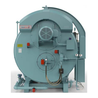
Boiler front view (67” boiler - configurations may vary) 11. Oil supply piping 7. Control panel/entrance panel 12. Air compressor 8. Low water cutoff 13. Bottom blowdown piping 9. Pressure controls 10. Safety valves FIGURE 1-3. Boiler side view (67” boiler - configurations may vary) 750-392 CBEX-DE... - Page 8 Introduction 1.2.1 — Blower assembly The blower assembly, also called the cassette, comprises the fan and motor and can be removed as a unit from the front of the boiler without open- ing the front door. The front davit arm is used to support the blower cassette during removal.
- Page 9 Butterfly Gas Valve (not shown): The pivoted disc in the valve is directly driven by a servo motor actuator to regulate the rate of gas flow to the burner. In optional 700-800 HP single point systems, the valve is driven by the modulating motor through connecting linkage. 750-392 CBEX-DE...
- Page 10 Introduction 1.2.4 — Pilot train FIGURE 1-7. Pilot train Gas Pilot Valve: A solenoid valve that opens during the ignition period to admit fuel to the pilot. It closes after main flame is established. The sequence of energizing and de-energizing is controlled by the programming relay.
- Page 11 All CBEX-DE boilers have the burner assembly integral with the front head. The burner drawer can be removed as a unit, or the entire head may be swung open for inspection and maintenance.
- Page 12 Introduction 1.2.6 — Oil system FIGURE 1-9. Front head oil piping The following items are applicable to all oil fired or gas and oil fired boilers. Oil Shutoff Valve: Opens when energized through contacts in the programmer and allows fuel oil flow from the oil metering valve to the burner nozzle.
- Page 13 The principal components of the HAWK 1000 are the Programmable Logic Control- ler (PLC), touch screen Human Machine Interface (HMI), and the Flame Safety Control. The system also includes 24VDC power supplies and various relays and circuit breakers. 750-392 CBEX-DE...
- Page 14 Introduction 1. Base Unit 1a. L24ER Programmable Logic Controller (PLC) 1b. Embedded I/O 2. SM2 Modbus Communications Module 3. Digital Inputs 4. Digital Outputs 5. Analog Inputs (optional) 6. Burner Control 7. Power supplies 8. Circuit breakers, relays, fuses, etc. 9.
- Page 15 The high limit pressure control is normally equipped with a manual reset. Pressure Transmitter: Senses changing boiler pressure and transmits a signal to the boiler control system. FIGURE 1-15. Steam Controls 1-11 750-392 CBEX-DE...
- Page 16 Introduction 1.2.10 — Temperature Controls (hot water boilers) High Limit Temperature Control: Breaks a circuit to stop burner operation on a rise of temperature at a selected setting. It is adjusted to stop the burner at a preselected temperature above the operating control setting. The high limit temperature control normally is equipped with a manual reset.
- Page 17 Lube Oil Cooling Coil: Cools the lubricating oil before it enters the air pump. A fan driven by the air pump motor circulates cooling air over the coil. Lube Oil Fill Pipe and Strainer: Used when adding oil to the air-oil receiver tank. 1-13 750-392 CBEX-DE...
- Page 18 Introduction 1.2.14 — Safety Valve(s) Safety valves prevent pressure in excess of the design pressure of the vessel. The size, rating, and number of valves on a boiler is determined by the ASME Boiler Code. The safety valves and the discharge piping are to be installed to conform to the ASME Code requirements.
-
Page 19: Waterside Care
NOTE: In the event that water column isolation valves are provided, it must be established that the valves are open and seated or locked in the open position. It is illegal to operate the boiler with closed or unseated open valves. 750-392 CBEX-DE... -
Page 20: Water Requirements - Hot Water Boilers
A rule of thumb of 3/4 to 1 gpm per boiler horsepower can be used to determine the minimum continuous flow rate through the boiler under all operating conditions. The operator should determine that a flow of water exists through the boiler before initial firing or refiring after boiler has been drained. 750-392 CBEX-DE... - Page 21 Some systems are pressurized with air, or with an inert gas such as nitrogen. Caution must be exercised to ensure that the proper relationship of pressure to temperature exists within the boiler so that all of the boiler’s internal surfaces are fully wetted at all times. 750-392 CBEX-DE...
-
Page 22: Water Treatment
Objectives of water treatment are: Prevent hard scale deposits or soft sludge deposits, which reduce heat transfer and can lead to overheated metal and costly downtime and repairs. 750-392 CBEX-DE... -
Page 23: Cleaning
The pressure vessel and the steam and return lines or hot water piping represent, in effect, a closed system. Although the steam and return (condensate) lines or the hot water piping system may have been previously cleaned, it is possible that: Cleaning has been inadequate. 750-392 CBEX-DE... -
Page 24: Boil-Out Of A New Unit
Water Volume - Flooded, Gal. 1589 1680 1718 2618 2515 2869 2630 2733 Water Weight - Operating, lbs. 9378 9915 9991 16926 14366 16393 14723 15300 Water Weight - Flooded, lbs. 13240 13996 14315 21805 20952 23899 21909 22765 750-392 CBEX-DE... - Page 25 NOTE: For new installations, refractory heat-curing can be accomplished at the same time as the boil out. Total firing time (firing intermittently at a low rate) should be 6-8 hours. The heat curing procedure is essential to prevent dam- age and cracking in the boiler refractory. 750-392 CBEX-DE...
-
Page 26: Washing Out
If the operator is absolutely certain that the system is tight, then an annual waterside inspection may be sufficient. However, if there is any doubt, the pressure vessel waterside should be inspected no later than three months after initially placing the boiler into operation, and periodically thereafter as indicated by conditions observed during inspections. 750-392 CBEX-DE... -
Page 27: Blowdown - Steam Boilers
Manual or sludge blowdown is necessary for the operation of the boiler whether or not continuous blowdown is employed. The blowdown tappings are located at the bottom or lowest part of the boiler in order to rid the sludge in the lower part of the vessel. 750-392 CBEX-DE... - Page 28 When continuous blowdown is utilized, manual blowdown is primarily used to remove suspended solids or sludge. The continuous blowdown removes sediment and oil from the surface of the water along with a pre- scribed amount of dissolved solids. 2-10 750-392 CBEX-DE...
- Page 29 Slightly crack the downstream valve and then close it tightly. Caution Do not pump the lever action valve open and closed, as water hammer is apt to break the valve bodies or pipe fit- tings. Failure to follow these instructions could cause damage to the equipment. 2-11 750-392 CBEX-DE...
-
Page 30: Periodic Inspection
Be certain that a supply of manhole and handhole gaskets is available, along with any other gaskets or items needed to place the unit back into operation after inspection. 2-12 750-392 CBEX-DE... -
Page 31: Preparation For Extended Layup
It is good practice to protect the cleaned surfaces by coating them with an anti-corrosive material to prevent rust. Swing open the boiler head at the stack end of the unit to prevent flow of warm, moist air through the boiler tubes. 2-13 750-392 CBEX-DE... - Page 32 Additional chemicals may be suggested by your local Cleaver-Brooks authorized representative to minimize corrosion. Internal water pressure should be maintained at greater than atmospheric pressure. Nitrogen is often used to pressurize the vessel. 2-14 750-392 CBEX-DE...
-
Page 33: Preparations For Startup
Prior to firing a boiler, be sure that discharge piping from safety valves or relief valves, and discharge piping from all blowdown and drain valves, is piped to a safe point of discharge, so that emission of hot water or steam cannot pos- sibly cause injury. Failure to follow these instructions could result in serious injury or death. 750-392 CBEX-DE... -
Page 34: Burner Operating Controls: General
On a high pressure steam boiler, the high limit control should be set approximately 10 psig above the operat- ing limit pressure control setting, if feasible, or midway between the operating limit pressure and the safety valve setting. 750-392 CBEX-DE... - Page 35 The burner will be “on” whenever the pressure or temperature is less than point B and “off” whenever pressure or temperature is greater than point A. The distance between points A and B represents the “on-off” differential of the operating limit control. 750-392 CBEX-DE...
- Page 36 If points B and C overlap when restart occurs, the burner would drive to a higher firing position immediately after the main flame was proven. It is therefore prudent to set the modulating control a few pounds or degrees below the operating control allowing the Low Fire to “catch the load” before releasing to modulation. 750-392 CBEX-DE...
-
Page 37: Control Checks
Proper operation of the flame failure device should be checked at startup and at least once a week thereafter. Check the program relay’s annunciation for any system failure. Observe the promptness of ignition of the pilot flame and the main flame. 750-392 CBEX-DE... -
Page 38: Low Water Cutoff Devices: Steam And Hot Water
The control adjustment may be made during the pre-purge period of operation by stopping the programmer during the pre-purge period through the use of the Run/Test switch. 750-392 CBEX-DE... -
Page 39: Gas Pilot Flame Adjustment
NOTE: On an initial starting attempt, portions of the fuel lines may be empty and require “bleeding” time. It is better to accomplish this with repeated short lighting trial periods with intervening purge periods than to risk prolonged fuel introduction. If the pilot does not light after several attempts, check all components of the pilot system. 750-392 CBEX-DE... -
Page 40: Gas Pressure And Flow Information
If the gas pressure regulator is furnished by others, instructions and adjusting proce- dures recommended by the manufacturer should be followed. 750-392 CBEX-DE... - Page 41 The pressures listed are based on 1000 Btu/cu ft natural gas at elevations up to 700 feet above sea level. For installation at higher altitudes, multiply the selected pressure by the proper factor from Table 3-3. 750-392 CBEX-DE...
- Page 42 Meters generally measure gas in cubic feet at “line” or supply pressure. The pressure at which each cubic foot is measured and the correction factor for the pressure must be known in order to convert the quantity indicated by the meter into the quantity which would be measured at “base” pressure. 3-10 750-392 CBEX-DE...
- Page 43 3 psig. Determine the flow rate by dividing the BTU content of the gas into the burner input and “correct” this answer by applying the correction factor for 3 psig, see Table 3-4. 3-11 750-392 CBEX-DE...
-
Page 44: Adjusting Combustion
In linkage adjustments there are several important factors that must serve as guides. • The modulating motor must be able to complete its full travel range. 3-12 750-392 CBEX-DE... - Page 45 Front head linkage: 1 - FGR (oil position shown) 2 - Mod motor 3 - Oil metering valve 4 - Air damper 5 - Gas butterfly valve FIGURE 3-3. Front head linkage option 3-13 750-392 CBEX-DE...
- Page 46 With the IFGR valve in the closed position, adjust the fixed ball stud quick disconnect on the proximity switch bracket. When setting the angle on the gas valve, make sure the arm is resting against and is in line with the stop bar. 3-14 750-392 CBEX-DE...
- Page 47 Linkage Settings (optional single-point systems) INITIAL LINKAGE SETTINGS Degrees Hole # Hole # Degrees Degrees Hole # Degrees Degrees 3/16 6-3/4 6-3/4 6-1/2 6-1/2 1-1/4 7-3/8 3-15 750-392 CBEX-DE...
- Page 48 Then run the screw out to touch the arm, and give it two complete turns. Adjust the connecting rod so that the override tension is released and so that the arm is now just touching the stop screw. Tighten the locknuts on all ball joints. 3-16 750-392 CBEX-DE...
- Page 49 (counterclockwise from the hex-socket end) to increase the flow of fuel, and inward (clockwise from the hex-socket end) to decrease it. Flow rate is highest when the cam follower assembly is closest to the jackshaft. 3-17 750-392 CBEX-DE...
- Page 50 If the air damper needs to be adjusted in order to provide the correct low-fire air/fuel ratio, combustion must be rechecked at higher firing rates and adjusted as required. If all cam screws are properly adjusted, none will deviate from the general overall contour of the cam face. 3-18 750-392 CBEX-DE...
-
Page 51: Low Gas Pressure Switch
However, regulations require that the setting may not be less than 50% of the rated pressure downstream of the regulator. Manual resetting is necessary after a pressure drop. Press the reset lever after pressure is restored. FIGURE 3-6. Gas Pressure Switches 3-19 750-392 CBEX-DE... -
Page 52: High Gas Pressure Switch
It is most important that oil spray does not impinge upon the diffuser. The distance that the nozzle is behind the diffuser has some latitude, and individual installation may require a slight deviation. FIGURE 3-7. Burner drawer adjustments 3-20 750-392 CBEX-DE... -
Page 53: Oil Drawer Switch
The switch is electrically removed from the circuit when a GAS PILOT combination fuel burner is fired on gas (fuel selector switch is FIGURE 3-8. Gas Pilot Electrode in GAS position). 3-21 750-392 CBEX-DE... - Page 54 Preparations for Startup 3-22 750-392 CBEX-DE...
-
Page 55: Startup And Operation
The burner control circuit is a two-wire system designed for 115 VAC, 60 Hz, single-phase power. The electrical portion of the boiler is made up of individual circuits with controls that are wired in a manner designed to provide a safe system. 750-392 CBEX-DE... - Page 56 To comply with requirements of insurance underwriters such as Factory Mutual (FM), XL GAP, or others, addi- tional interlock devices may be used in addition to the circuits identified in section 4.2. For additional information see the CB780E manual, 750-234. 750-392 CBEX-DE...
- Page 57 NOTE: If the main flame does not light, or stay lit, the fuel valve will close. The safety switch will trip to lock out the control. Refer to flame loss sequence below for description of action. 750-392 CBEX-DE...
-
Page 58: Flame Loss Sequence
Lockout will also occur if flame or flame simulating condition occurs during the pre-purge period. The control will prevent startup or ignition if limit circuit controls or fuel valve interlocks are open. The control will lock out upon any abnormal condition affecting air supervisory controls wired in the running interlock circuit. 750-392 CBEX-DE... - Page 59 Preventive maintenance and scheduled inspection of all components should be followed. Periodic checking of the relay is recommended to see that a safety lockout will occur under conditions of failure to ignite either pilot or main flame, or from loss of flame. 750-392 CBEX-DE...
-
Page 60: General Preparation For Startup: All Fuels
Inspect the low-water cutoff and pump control as well as the auxiliary low-water cutoff (if so equipped). See manual 750-281 for complete information on the CB Level Master. 750-392 CBEX-DE... -
Page 61: Control Settings: Steam And Hot Water
The supply and pressure of the atomizing air on an oil-fired burner should be checked. Before starting, inspect the oil pump lube oil level. Add oil if necessary to bring the level to the mid-point or slightly higher in the sight glass. Use SAE 20 detergent oil or ISO-68 hydraulic fluid. 750-392 CBEX-DE... - Page 62 The air pressure should not exceed 35 psi at high-fire. Greater air pressure causes excessive wear of the air pump, increases lube oil usage, and can overload the motor, thus causing damage to the equipment. After air flow has been verified, turn the burner switch off and return the run/test switch to the “run” position. 750-392 CBEX-DE...
-
Page 63: Firing Preparations For No. 2 Oil (Series 100, 200)
If oil flow is not readily established, avoid prolonged operation of the pump to minimize risk of damage to internal parts of the pump. If oil flow is not established after a second or third priming attempt, a full investigation is required to determine the cause. 750-392 CBEX-DE... - Page 64 FIGURE 4-4. Oil Terminal Block increases. After the burner is firing and when the air pump is run- ning, final adjustment can be made at the fuel oil controller. Fuel Oil Actuator FIGURE 4-5. 4-10 750-392 CBEX-DE...
-
Page 65: Firing Preparations For Gas (Series 200, 700)
The burner and control system are designed to provide a “pre-purge” period of fan operation prior to establishing igni- tion spark and pilot flame. Do not attempt to alter the system or take any action that might circumvent the “pre- purge” feature. Failure to follow these instructions could result in serious injury or death. 4-11 750-392 CBEX-DE... -
Page 66: Startup, Operating, And Shutdown: All Fuels
NOTE: On an initial starting attempt, several efforts might be required to accomplish “bleeding” of fuel lines, main or pilot. If ignition does not then occur, do not repeat unsuccessful attempts without rechecking the burner and pilot adjustment. 4-12 750-392 CBEX-DE... - Page 67 The burner will continue to operate with modulated firing until the operating limit pressure or temperature is reached, unless: The burner is manually turned “off.” A low-water condition is detected by low-water level control. The electrical or fuel supply is interrupted. 4-13 750-392 CBEX-DE...
-
Page 68: Control Operational Checks
Return the manual-automatic switch to “automatic” and check the modulating control for the desired tempera- ture range. Check the proper operation and setting of the low-water cutoff (and pump operating control, if used). For C-B Level Master, see manual 750-281. 4-14 750-392 CBEX-DE... -
Page 69: Troubleshooting
Refer to the schematic wiring diagram for terminal identification. Warning Disconnect and lockout the main power supply in order to avoid the hazard of electrical shock. Failure to follow these instructions could result in serious injury or death. 4-15 750-392 CBEX-DE... - Page 70 Promptly correct any conditions causing leakage. Failure to do so may result in serious personal injury or death. The Hawk control system has the capability to self-diagnose and to annunciate flame safeguard and other sys- tem faults. Refer to the Hawk and flame safeguard manuals for specifics and suggested remedies. 4-16 750-392 CBEX-DE...
- Page 71 A. Damper motor not closed, slipped cam, defective switch. B. Damper jammed. Running interlock circuit not completed. A. Combustion or atomizing air proving switches defective or not properly set. B. Motor starter interlock contact not closed. Flame detector defective, sight tube obstructed, or lens dirty. 4-17 750-392 CBEX-DE...
- Page 72 Improper air/fuel ratio (lean fire): A. Slipping linkage. B. Damper stuck open. C. Fluctuating fuel supply: 1) Temporary obstruction in fuel line. 2) Temporary drop in gas pressure. Interlock device inoperative or defective. 4-18 750-392 CBEX-DE...
-
Page 73: Emergency Shutdown
“OFF” position. Shut off the main manual fuel shutoff valves on the fuel supply line. The unit can also be shut down with the main electrical power disconnect. Inspect the burner carefully and troubleshoot before restarting the unit. 4-19 750-392 CBEX-DE... - Page 74 Startup and Operation 4-20 750-392 CBEX-DE...
-
Page 75: Inspection And Maintenance
Any leaks — fuel, water, steam, exhaust gas — should be repaired promptly and under conditions that observe necessary safety precautions. Preventive maintenance measures, such as regularly checking the tightness of connections, locknuts, setscrews, packing glands, etc., should be included in regular maintenance activities. 750-392 CBEX-DE... -
Page 76: Periodic Inspection
NOTE: To ensure proper operation, use only Cleaver-Brooks genuine parts. Contact your local Cleaver-Brooks repre- sentative for parts information and ordering. 750-392 CBEX-DE... -
Page 77: Fireside Cleaning
Check operation frequently by stopping water flow to the boiler, allowing water level to lower. If controls do not cut off burner at proper safe water level or are seen to be in poor physical condition, repair or replace at once. 750-392 CBEX-DE... -
Page 78: Water Gauge Glass
If they are not, the glass will be strained and may fail prematurely. Warning Do not attempt to change the gauge glass while the boiler is in service. Failure to follow these instructions could result in serious injury or death. FIGURE 5-1. Water Column Gauge Glass Replacement 750-392 CBEX-DE... -
Page 79: Electrical Controls
Be sure the connecting contacts on the control and its base are not bent out of position. The flame detector lens should be cleaned as often as operating conditions demand. Use a soft cloth moistened with detergent to clean the lens. 750-392 CBEX-DE... - Page 80 The flame failure light (and optional alarm) will be activated. The blower motor will run through the post-purge and stop. Turn the burner switch off. Reset the safety switch. Re-establish main fuel supply. 750-392 CBEX-DE...
-
Page 81: Removing Burner Drawer
The burner should be inspected for evidence of damage due to improperly adjusted combustion. Any soot buildup on the diffuser or the oil nozzle should be removed. The positioning of the oil nozzle in relation to the diffuser and other components is important for proper firing and should be checked. 750-392 CBEX-DE... - Page 82 Check ignition cables for cracks in the insulation. Also see that all connections between the transformer and the electrodes are tight. Periodically remove the access plug from the gas pilot aspirator and clean out any accumu- lated lint or other foreign material. 750-392 CBEX-DE...
-
Page 83: Gas Burner Maintenance
Periodically remove the access plug from the gas pilot venturi and clean out any accumulated lint or other foreign material. ACCESS PLUG FIGURE 5-4. Gas pilot venturi Check the ignition cables for cracks in the insulation. Verify that all connections between the transformer and the electrode are tight. 750-392 CBEX-DE... -
Page 84: Motorized Gas Valve
Any resistance to movement or excessive play in the support bearing should be investigated and cor- rected before the burner is put back in operation. Ensure the gears are fully engaged throughout the entire damper rotational range. 5-10 750-392 CBEX-DE... -
Page 85: Fan/Motor Cassette Removal
Disconnect and lock out electric power to the boiler. Be sure that the front door is securely bolted to the boiler. Release the davit arm by removing the retaining bolt at the top center of the boiler. 5-11 750-392 CBEX-DE... -
Page 86: Ifgr Inspection And Adjustment
If adjustment is required, or if problems persist, contact your local Cleaver-Brooks autho- rized representative for further assistance. As ash and products of combustion pass through the IFGR damper, there will be some accumulation on the damper, windbox, and other parts of the IFGR system and burner. 5-12 750-392 CBEX-DE... -
Page 87: Fan/Motor Cassette Replacement
Do not remove the davit arm assembly from the motor/fan cassette without first verifying that the cassette is securely bolted to the boiler. Failure to follow these instructions could result in serious injury or death. Position the cassette into the front door. 5-13 750-392 CBEX-DE... -
Page 88: Safety Valves
Avoid having the operating pressure too near the safety valve set pressure. A 10% differential is recommended. An even greater differential is desirable and will assure better seat tightness and valve longevity. 5-14 750-392 CBEX-DE... -
Page 89: Fuel Oil Metering Valve
Replace the gasket, put the support in place, and secure all fastenings. Replace the metering stem and spring. Lightly lubricate the stem to facilitate insertion and easy movement. Use care when inserting so that the orifice and the stem are not damaged. 5-15 750-392 CBEX-DE... - Page 90 Remove the valve cover and the diaphragm to expose any dirt or foreign material which may have entered the valves. Clean out carefully and reassemble. It is recommended that the diaphragms be replaced annually. 5-16 750-392 CBEX-DE...
-
Page 91: Air Pump And Lubricating System
5.18.3 — Lubricating Oil Strainer and Cooling Coil Air pressure from the pump forces lubricating oil from the tank through a cooling coil to the pump. The oil lubri- cates the pump bearings and also provides a seal and lubrication for the pump vanes. 5-17 750-392 CBEX-DE... - Page 92 Follow previous instructions for oil replacement. FIGURE 5-12. Air-Oil Receiver Tank 5.18.5 — Air Cleaner Never operate the air pump without the air cleaner in place. The cleaner itself must be periodically checked and its element flushed and cleaned semi-annually. 5-18 750-392 CBEX-DE...
- Page 93 5.18.7 — Air Compressor Replacement Do not attempt field repairs on the compressor. An inoperative unit should be replaced. Use the following proce- dures when replacing the pump. Be sure to tag the motor leads if disconnected to simplify re-connection. 5-19 750-392 CBEX-DE...
- Page 94 If the motor was replaced or if motor leads were disconnected, be sure that pump rotation is proper before start- ing operation. The air pump should rotate in a clockwise direction, as viewed from the drive shaft end. 5-20 750-392 CBEX-DE...
-
Page 95: Refractory
Re-coating intervals will vary with operating loads and are best determined by the operator when the boiler is opened for inspection. FIGURE 5-14. Throat Tile and Furnace Liner 5-21 750-392 CBEX-DE... - Page 96 Remove any cement that is squeezed out. Allow refractory to air dry as long as possible. If immediate use is required, fire intermittently at a low rate for several hours to thoroughly dry the refractory. 5-22 750-392 CBEX-DE...
- Page 97 After joint cement hardens (approximately 2 hours), remove bricking tool, wooden tile supports, and discard cerafelt shims. FIGURE 5-17. Liner tile installation ARCH BRICK INSTALLATION TOOL 30/60/UC NOx BOILER SIZE TOOL PART NUMBER 250-350 HP 098-00280 400 HP 098-00333 500-600 098-00375 700-800 098-00279 5-23 750-392 CBEX-DE...
- Page 98 8) After each half course of bricks or tiles is installed, clean up excess cement and fill open joint areas where necessary. 400 HP 250-350 HP 120° SEE NOTE #1 120° SEE NOTE #1 FIGURE 5-18. Throat tile and furnace liner installation notes 67” and 78” boilers 5-24 750-392 CBEX-DE...
- Page 99 Do not fill the first half corrugation (30 PPM only). 700-800 HP 500-600 HP 120° (See Note #1 120° (See Note #1) (See Note #8) (See Note #8) FIGURE 5-19. Throat tile and furnace liner installation notes 83” boilers 5-25 750-392 CBEX-DE...
-
Page 100: Front And Rear Access
Clean the sealing surfaces of the door and tube sheet. If the blanket insulation is torn away the insulation will require replacing. CLAMP RING CAPSCREWS 2. REMOVE INNER PLATE CLAMPS 1. REMOVE BURNER DRAWER 3. REMOVE CLAMP RING AND DOOR CAPSCREWS FIGURE 5-20. Opening front door FIGURE 5-21. Gasket, front & rear door 5-26 750-392 CBEX-DE... - Page 101 After the boiler is back in operation, re-tighten the door bolts to compensate for compression of the gasket or movement of the door. GASKET 1-1/2” ROPE BLANKET 2”x1/2” FIGURE 5-22. Rear door 5-27 750-392 CBEX-DE...
-
Page 102: Lubrication
Readjustment of the burner may be required due to variations in fuel composition. A combustion analyzer should be used to adjust air-fuel ratio for maximum operating efficiency. If your burner requires adjustments, contact your local Cleaver-Brooks authorized representative for assistance. 5-28 750-392 CBEX-DE... -
Page 103: Linkage Systems
Lubricate occasionally with a non-gumming, dripless, high-temperature lubricant such as graphite or a silicone derivative. Combustion should be checked and readjusted whenever the burner is removed or any control linkage is dis- turbed. 5-29 750-392 CBEX-DE... - Page 104 Inspection and Maintenance 5-30 750-392 CBEX-DE...
-
Page 105: Chapter 6 Parts
Rear Head ............19 VESSEL SIZE BOILER HP 67” 250-350 78” 83” 500-800 Boiler data plate 750-392 CBEX-DE... -
Page 106: Parts
101-200 FUEL USED ON 700 FUEL ASSY #6 P/N #9 P/N #12 P/N #19 P/N #25 P/N "D" DIM "E" DIM ASSY 400HP CBEX-DE 30 PPM 429-02214-000 090-04973-000 090-04976-000 090-04974-000 251-00430-000 3/8" 275-01416-000 25-3/8" 429-02215-000 400HP CBEX-DE 30 PPM 275-01416-000... - Page 107 MICA SHEET, SIGHT HOLE 857-00740-000 NIPPLE, PIPE USAGE ITEM 27 500 HP 30PPM 275-02001-000 500 HP 60PPM 275-02715-000 600 HP 30PPM 275-00303-000 600 HP 60PPM 275-02716-000 700 HP 30-60PPM 275-00303-000 800 HP 30-60PPM 275-00304-000 SECTION B-B " SECTION A-A 750-392 CBEX-DE...
- Page 108 022-00133-000 DIFFUSER - AIR STABILIZER, FRONT Note: Damper Arm (Item #6) Is Required For FARC And Non-Parallel Positioning. 30° (Oil) Section A- (Air) (Air) (Oil) Section .250 .375 Gap .438 Diff. Face Section C-C .188 Detail E Section B-B 750-392 CBEX-DE...
-
Page 109: Arch Brick And Liner Tile
DIM "E" 700-800 30 PPM 3280 IN² 40 LBS 16" 094-00451-000 098-00279-000 30 ppm 3110 IN^2 30 LBS 16" 094-01010-000 098-00375-000 5-9 PPM 19" 094-00795-000 098-00338-000 5-9 PPM 20-3/4" 094-01012-000 098-00378-000 Ø 47.000 Ref. 45.000 Ref. "E" "E" 750-392 CBEX-DE... -
Page 110: Front Head
132-01729-000 465-02484-000 132-01732-000 UC/60 TABLE 2 ASSEMBLY NO. IFGR RATE ITEM #1 ITEM #25 132-01734-000 (RH) 30 PPM 132-01736-000 465-01680-000 132-01738-000 (RH) 60 PPM 132-01736-000 132-01739-000 (LH) 30 PPM 132-01737-000 465-01680-000 132-01740-000 (LH) 60 PPM 132-01737-000 SECTION A-A 750-392 CBEX-DE... - Page 111 RH - 30 PPM 132-01741-000 132-01745-000 465-02518-000 Not Required RH - 60 PPM 132-01742-000 132-01745-000 LH - 30 PPM 132-01743-000 132-01746-000 465-02518-000 LH - 60 PPM 132-01744-000 132-01746-000 Not Required REAR VIEW DETAIL C DETAIL B SECTION A-A 750-392 CBEX-DE...
-
Page 112: Blower Cassette
Parts 6.4 — Blower Cassette NOTE: Impeller size is based on boiler HP, ppm emission level, boiler operating pressure and altitude. To ensure proper selection of impellers and other blower cassette components, contact Cleaver-Brooks Aftermarket. UNCONTROLLED UNCONTROLLED UNCONTROLLED 750-392 CBEX-DE... -
Page 113: Modbus Actuators (Parallel Positioning)
"B"* NOTES: 1) DIMENSIONS "A" AND "B" ARE FOR REFERENCE ONLY. 2) ENSURE GEAR TEETH ARE FULLY ENGAGED THROUGHOUT THE ENTIRE AIR DAMPER OPERATIONAL ROTATION RANGE. VIEW A-A 3) CONNECTOR TO BE INSTALLED WITH 1/16" CLEARANCE FROM ACTUATOR. 750-392 CBEX-DE... - Page 114 4" VALVE 008-03522-000 845-01082-000 SEE TABLE ACTUATOR 868-00209-000 CAPSCREW ITEM #4 952-00117-000 LOCK WASHER ASSY WITH QUICK DISCONNECTS ASSY WITHOUT QUICK DISCONNECTS 952-00144-000 WASHER 945-00259-000 945-00375-000 GAS VALVE REMOVE FOOT SUPPLIED W/ GAS VALVE AND USE SCREWS 6-10 750-392 CBEX-DE...
- Page 115 952-00117-000 LOCK WASHER, #10 PLAIN STEEL 952-00144-000 WASHER, FLAT, 3/16" 952-00145-000 WASHER, FLAT, 1/4" SEE CHART OIL VALVE STEM ASSY ITEM #13 ASSY # 269-00153-0QC - WITH QUICK DISCONNECTS ASSY # 269-00153-000 WITHOUT QUICK DISCONNECTS 945-00259-000 945-00375-000 6-11 750-392 CBEX-DE...
-
Page 116: Gas Train
Aftermarket for information regarding your specific application. PILOT GAS TRAIN ELBOW ASSEMBLY PILOT GAS TRAIN ASSEMBLY PILOT TUBING ASSEMBLY LGPS ASSY. MANIFOLD PRESSURE HGPS GAUGE ASSEMBLY ASSY. SSOV ASSY. VPS or VENT VALVE ASSEMBLY STARTER DOWN STREAM TRAIN ASSEMBLY ASSEMBLY TRANSITION ASSEMBLY 6-12 750-392 CBEX-DE... -
Page 117: Light Oil Components
Description 106-00012-000 BLOCK, OIL TERMINAL 843-00176-000 FILTER 850-02359-000 GAUGE, PRESSURE 940-02296-000 VALVE, RELIEF FUEL OIL CONTROLLER FUEL OIL CONTROLLER PART NO. MODEL 739-00073-000 250 - 350 HP 739-00074-000 400 - 700 HP 739-00079-000 750 - 800 HP 6-13 750-392 CBEX-DE... - Page 118 LOPS, PRESSURE CONTROL, OP. LIMIT, DANFOSS, 150 PSI 817-04093-000 HOPS, PRESSURE CONTROL, OP. LIMIT, DANFOSS, 150 PSI 817-04093-000 I F R E Q U I R E D 6.7.3 — Light OIl Pilot (100 Fuel Series only) FUEL OIL CONTROLLER STANDARD (XL GAPS) 6-14 750-392 CBEX-DE...
-
Page 119: Low Water Cutoff
Item Qty Description Part # LWCO & Pump Control 817-02374 Ball Valve 941-00055 Gate Valve 941-01886 500-800HP SELECT APPROPRIATE GAUGE GLASS ASSEMBLY Item Qty Description Part # LWCO & Pump Control 817-01384 Ball Valve 941-00055 Gate Valve 941-01886 6-15 750-392 CBEX-DE... -
Page 120: Auxiliary Low Water Cutoff
500-800 941-01657 941-01657 Gate Valve 941-01886 MDM 150S-B-M Item Description Boiler HP 15 PSI Part # 150 PSI Part # ALWCO Control 250-800 817-02407 817-02407 Ball Valve 250-350 941-01790 Gate Valve 500-800 941-01886 Gate Valve 250-800 941-01886 6-16 750-392 CBEX-DE... -
Page 121: Pressure Controls, Steam
HIGH LIMIT, 1/4", 200 PSI 817-04148-000 DESIGN PRESSURE = 200PSIG HIGH LIMIT, 1/4", 250 PSI 817-04149-000 DESIGN PRESSURE = 250 PSIG 817-04073-000 HIGH LIMIT, 1/4", 300 PSI DESIGN PRESSURE = 300 PSIG MOD ULATING CONTROL (NON-HAWK) SHOWN 6-17 750-392 CBEX-DE... -
Page 122: Temperature Controls, Hot Water
Parts 6.11 — Temperature Controls, Hot Water 6-18 750-392 CBEX-DE... -
Page 123: Rear Head
BALL BEARING, DOUBLE ROW 019-01362-000 019-01362-000 019-01361-000 COVER, BEARING 287-00094-000 287-00085-000 287-00097-000 ARM, REAR DAVIT 077-00385-000 077-00385-000 SPACER, DAVIT 077-00386-000 807-00319-000 807-00319-000 807-00326-000 BALL BEARING, SINGLE ROW 952-00193-000 WASHER 914-00158-000 914-00158-000 RING,RETAINING 056-00025-000 056-00025-000 056-00066-000 PIN, HINGE, DAVIT 6-19 750-392 CBEX-DE...
Need help?
Do you have a question about the CBEX-DE and is the answer not in the manual?
Questions and answers