Table of Contents
Advertisement
Advertisement
Table of Contents

Related Manuals for CleaverBrooks CFC-E Series


Summary of Contents for CleaverBrooks CFC-E Series
- Page 1 CFC-E ClearFire Condensing Boiler Boiler Book 02/2018...
-
Page 2: Table Of Contents
BOILER BOOK CFC-E Table of Contents FEATURES AND BENEFITS ..............4 PRODUCT OFFERING . - Page 3 BOILER BOOK CFC-E Model CFC-E Minimum Over Pressure Requirements ..........21 Safety Relief Valve Information .
-
Page 4: Features And Benefits
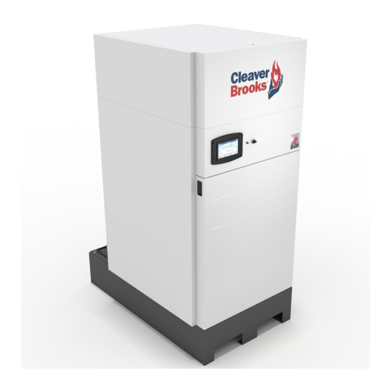
BOILER BOOK CFC-E FEATURES AND BENEFITS FEATURES AND BENEFITS Compact Firetube Design The Model CFC-E boiler is a high mass, vertical down fired robust firetube boiler. The internal extended-heating surface tubes provide very high levels of performance in a compact space. The large water volume makes the CFC-E ideal for variable flow primary pumping systems. - Page 5 BOILER BOOK CFC-E FEATURES AND BENEFITS linear load tracking, reduced on-off cycling, and reduced electrical consumption. Figure 2. Premix Burner Technology Designed For Heating Applications The pressure vessel is designed for 125 psig MAWP (Maximum Allowable Working Pressure) and is constructed of durable ASTM Grade Steel and Stainless Steel materials.
-
Page 6: Product Offering
BOILER BOOK CFC-E PRODUCT OFFERING PRODUCT OFFERING Dimensions, ratings, and product information may change to meet current market requirements and product improvements. Therefore, use this information as a guide. Standard Equipment Equipment described below is for the standard boiler offering: 1. - Page 7 BOILER BOOK CFC-E PRODUCT OFFERING Figure 3. ClearFire CE Control Panel 4. Forced Draft Burner A. The burner is a “Pre-mix” design consisting of a unitized venturi, single body dual safety gas valve, blower, and burner head. Consistent fuel-air ratio is maintained with a self-regulating gas valve-venturi system which automatically compensates for changes in air density.
-
Page 8: Dimensions And Ratings
BOILER BOOK CFC-E DIMENSIONS AND RATINGS • High Gas Pressure Interlock, manual reset. • ASME CSD-1 Test Cocks. • Downstream manual ball type shutoff valve. • Single body dual safety shutoff gas valve. Optional Equipment For option details, contact the local authorized Cleaver-Brooks representative. In summary, here are some of the options that can be provided with the boiler: Reusable air filter. - Page 9 BOILER BOOK CFC-E DIMENSIONS AND RATINGS OPTIONAL ADJUSTABLE FEET ALLOW FOR 1.56” TO 3.88” ADDITIONAL HEIGHT Figure 4. Model CFC-E Dimensional Views...
- Page 10 BOILER BOOK CFC-E DIMENSIONS AND RATINGS Table 1. U.S. Standard Dimensions Model CFC-E Boiler ITEM DIMENSIONS (inches) 1000 1500 2000 Overall Height 78.0 78.0 78.0 79.9 79.9 Overall Width 34.9 34.9 34.9 35.8 35.8 Overall Depth 49.4 49.4 49.4 Width Less Casing 32.1 32.1 32.1...
- Page 11 BOILER BOOK CFC-E DIMENSIONS AND RATINGS Table 2. Dimensions (Metric) Model CFC-E ITEM DIMENSIONS (mm) 1000 1500 2000 Overall Height 1982 1982 1982 2028 2028 Overall Width Overall Depth 1255 1255 1255 1422 1422 Width Less Casing Gas Connection to Floor 1786 1786 1786...
- Page 12 BOILER BOOK CFC-E DIMENSIONS AND RATINGS Table 3. Model CFC-E Boiler Ratings (Sea Level to 2000 Feet) Boiler Size Description Units 1000 1500 2000 Input Max. Btu/Hr 500,000 750,000 1,000,000 1,500,000 2,000,000 KCal/Hr 126,000 189,000 252,000 378,000 504,000 1000 1500 2000 Natural Gas Propane...
-
Page 13: Performance Data
BOILER BOOK CFC-E PERFORMANCE DATA Table 4. Altitude Correction for Input Capacity at Various Altitude Levels Natural Gas MBTU/h at various altitudes 700' ASL 2000' 4000' 6000' 8000' 10000' 2000 2000 1883 1747 1619 1552 CFC-E 2000 1500 1500 1500 1500 1500 1472... - Page 14 BOILER BOOK CFC-E PERFORMANCE DATA Table 5. CFC-E Efficiencies CFC-E 500 Efficiency Return Water Temperature °F ( °C ) % Firing Rate (20) (27) (38) (49) (55) (60) (72) 99.0 97.8 96.1 92.4 90.4 88.9 88.1 97.9 96.7 94.7 91.5 89.9 88.6 87.9...
- Page 15 BOILER BOOK CFC-E PERFORMANCE DATA Figure 5. Efficiency 500 CFC-E 500 Efficiency Curve 20% Firing Rate 50% Firing Rate 75% Firing Rate 100% Firing Rate °F) Return Water Temperature ( 40° F Temperature Di eren al Figure 6. Efficiency 750 CFC-E 750 Efficiency Curve 20% Firing Rate 50% Firing Rate...
- Page 16 BOILER BOOK CFC-E PERFORMANCE DATA Figure 7. Efficiency 1000 CFC-E 1000 Efficiency Curve 20% Firing Rate 50% Firing Rate 75% Firing Rate 100% Firing Rate Return Water Temperature ( °F) 40°F Temperature Di eren al Figure 8. Efficiency 1500 CFC-E 1500 Efficiency Curve 20% Firing Rate 50% Firing Rate 75% Firing Rate...
-
Page 17: Noise Level (Dba) Measured 3 Feet In Front Of Boiler
BOILER BOOK CFC-E PERFORMANCE DATA Figure 9. Efficiency 2000 CFC-E 2000 Efficiency Curve 20% Firing Rate 50% Firing Rate 75% Firing Rate 100% Firing Rate Return Water Temperature ( °F) 40°F Temperature Di eren al Emissions By means of the Pre-mix burner, the Clearfire boiler provides environmentally friendly emissions when firing natural gas;... -
Page 18: Engineering Data
BOILER BOOK CFC-E ENGINEERING DATA ENGINEERING DATA Boiler Information The Model CFC-E boiler is designed for service in any closed hydronic system. It can be put into operation as a single stand-alone unit with 5:1 turndown or in multiple units for larger turndown and capacity. - Page 19 BOILER BOOK CFC-E ENGINEERING DATA Figure 10. Waterside Pressure Drop CFC-E 500 Flow Rate (gpm) Figure 11. Waterside Pressure Drop CFC-E 750...
- Page 20 BOILER BOOK CFC-E ENGINEERING DATA Figure 12. Waterside Pressure Drop CFC-E 1000 Figure 13. Waterside Pressure Drop CFC-E 1500...
-
Page 21: Model Cfc-E Minimum Over Pressure Requirements
BOILER BOOK CFC-E ENGINEERING DATA Figure 14. Waterside Pressure Drop CFC-E 2000 System Operating Parameters To prevent water flashing to steam within the boiler or system, hot water boilers must operate with proper over-pressure. System over-pressure requirements are shown in Table 9. Maximum Allowable Working Temperature (MAWT) is 210°F (99°C). -
Page 22: Safety Relief Valve Information
BOILER BOOK CFC-E ENGINEERING DATA Table 10. Safety Relief Valve Information @125 psig Model Inlet (NPT) Outlet (NPT) Valve Capacity (MBH) CFC-E 500 3/4” 1" 3364 CFC-E 750 3/4” 1" 3364 CFC-E 1000 3/4” 1" 3364 CFC-E 1500 3/4” 1" 3364 CFC-E 2000 3/4”... - Page 23 BOILER BOOK CFC-E ENGINEERING DATA Water Treatment Even though hot water systems are “closed”, some amount of make-up water (up to 10%) will be introduced. This more often than not happens from seal leaks of pumps, or other minimal leaks from valves etc., that go unnoticed.
- Page 24 BOILER BOOK CFC-E ENGINEERING DATA Independent from the hydraulics of the heating system, constant water circulation through each boiler is required while the boiler is operating (requires a dedicated boiler pump if in a primary/secondary loop arrangement). Refer to table below for minimum boiler circulation rates. Minimum over-pressure at the boiler: For outlet temperatures up to the maximum of 185 deg F (85 deg C), a minimum operating pressure of 30 psig (2.1 bar) is required.
-
Page 25: Maximum Firing Rate Vs. % Glycol
BOILER BOOK CFC-E ENGINEERING DATA Figure 15. High Fire Speed Settings vs. % Glycol CFC-E High Fire Blower Speed Se ng vs. % Glycol 6200 CFC-E 750 6100 CFC-E 500/1000 6000 CFC-E 1500 5900 5800 CFC-E 2000 5700 5600 5500 5400 5300 5200... -
Page 26: Neutralization Capsule
BOILER BOOK CFC-E ENGINEERING DATA Condensation The CFC-E uses one of several condensate removal options, depending on the application: (1) Condensate direct to drain - The condensate is piped directly to a drain through the piping and water trap supplied during installation (see Figure 17). •... -
Page 27: Combo Trap/Tank
BOILER BOOK CFC-E ENGINEERING DATA (3) Combo trap/treatment tank - The condensate is held in a condensate tank under the boiler. The condensate is neutralized as it passes through the granular bed. The neutralized condensate is then piped to the drain. The combo tank features an integral water trap and float makeup valve. -
Page 28: Treatment Tank
BOILER BOOK CFC-E ENGINEERING DATA FROM BOILER 1" FNPT 1" FNPT outlet inlet TO DRAIN Figure 20. Treatment Tank Condensate Piping for Multiple Boilers Table 13. Condensate piping for multiple boilers CFC-E BTU/hr Max. Max. Boilers Model Condensation per Tank 2000 2,000,000 13.5... -
Page 29: Condensate Piping For Multiple Boilers
BOILER BOOK CFC-E ENGINEERING DATA Total boiler capacity per condensate tank should not exceed 8,000,000 BTU/hr Figure 21. Condensate Piping for Multiple Boilers Figure 22. Tank Detail, Multiple Boilers Gas Fuel Connections The local Gas Company should be consulted for the requirements for installation and inspection of gas supply piping. - Page 30 BOILER BOOK CFC-E ENGINEERING DATA Relief V alve (NOT E 5) M anual Shutoff Regulator G as header - size for boiler room (NOT E 1) capacity and to minimize pressure loss Strainer M anual Shutoff Same or larger than boiler gas connection size D rip leg required for any vertical run of piping = optional or by others Figure 23.
-
Page 31: Gas Header Piping
BOILER BOOK CFC-E ENGINEERING DATA M eter H eader Pipe G as Strainer M anual Shut O ff R egulator See N ote 1 R elief V alve See N ote 5 N O T ES: 1. D edicated gas pressure regulator recommended for each boiler. G as H eader Piping, T ypical 2. -
Page 32: Model Cfc-E Minimum Required Gas Pressure Altitude Correction
BOILER BOOK CFC-E ENGINEERING DATA Table 15. Model CFC-E Minimum Required Gas Pressure Altitude Correction Altitude in Feet Correction Factor Altitude in Feet Correction Factor 1000 1.04 6000 1.25 2000 1.07 7000 3000 1.11 8000 1.35 4000 1.16 9000 5000 1.21 To obtain minimum required inlet pressure, select altitude of installation and multiply the pressure shown in Table 13 by the correction factor corresponding to the altitude listed above. -
Page 33: Model Cfc-E Minimum Room Clearance Dimensions
BOILER BOOK CFC-E ENGINEERING DATA Figure 25. Model CFC-E Minimum Room Clearance Dimensions Seismic Legs Seismic mounting details shown below. 2” 7/16" HOLE 2” DIM. 1000 1500 2000 "A" 34.35" 34.35" 35.25" 35.25" 54" 54" "B" 47.4" 47.4" "C" 17.175” 17.175”... - Page 34 BOILER BOOK CFC-E ENGINEERING DATA Boiler Room Combustion and Ventilation Air The boiler(s) must be supplied with adequate quantities of uncontaminated air to support proper combustion and equipment ventilation. Air shall be free of chlorides, halogens, fluorocarbons, construction dust or other contaminants that are detrimental to the burner/boiler. If these contaminants are present, we recommend the use of direct vent combustion provided the outside air source is uncontaminated.
- Page 35 BOILER BOOK CFC-E ENGINEERING DATA Figure 27. Two Opening Outside Wall Method B. All Air From Outdoors - If all combustion air will be received from outside the building (the mechanical room equipment is linked with the outdoors), the following methods can be used: 1.
- Page 36 BOILER BOOK CFC-E ENGINEERING DATA Figure 28. Two Opening Ducted Method C. One Opening Method (Figure 29) - One permanent opening, commencing within 12 inches of the top of the enclosure, shall be provided. 1. The equipment shall have clearances of at least 1 inch from the sides and back and 6 inches from the front of the appliance.
-
Page 37: One Opening Method
BOILER BOOK CFC-E ENGINEERING DATA Figure 29. One Opening Method Unconfined Space/Engineered Design When determining boiler room air requirements for unconfined space, the size of the room, airflow, and velocity of air must be reviewed as follows: 1. Size (area) and location of air supply openings in the boiler room. A. - Page 38 BOILER BOOK CFC-E ENGINEERING DATA Figure 30. Two Opening Engineered Method E. Size the openings by using the formula: Area in square feet = cfm/fpm Where cfm = cubic feet per minute of air Where fpm = feet per minute of air 2.
-
Page 39: Stack/Breeching Size Criteria
BOILER BOOK CFC-E STACK/BREECHING SIZE CRITERIA Boiler Air Inlet The boiler ships with both an air inlet screen and a direct vent collar (see illustration below). If room air will be used for combustion, install the air inlet screen; the collar may be discarded. If direct venting will be used, install the vent collar;... - Page 40 BOILER BOOK CFC-E STACK/BREECHING SIZE CRITERIA The design of the stack and breeching must provide the required draft at each boiler flue gas connection; proper draft is critical to burner performance. Although constant pressure at the flue gas outlet is not required, it is necessary to size the breeching and stack to limit flue gas pressure variation.
- Page 41 BOILER BOOK CFC-E STACK/BREECHING SIZE CRITERIA U.S. Installations Refer to the latest edition of the National Fuel Gas Code/NFPA 54. Vent termination requirements are: 1. Vent must terminate at least four feet below and four feet horizontally or one foot above any door, window or gravity air inlet to the building.
-
Page 42: Horizontal Through-Wall Venting Using Inside Air For Combustion
BOILER BOOK CFC-E STACK/BREECHING SIZE CRITERIA Figure 32. Horizontal through-wall venting using inside air for combustion The vent must be installed to prevent the potential accumulation of stack condensate in the horizontal run of vent pipe. Therefore, it is recommended that: 1. - Page 43 BOILER BOOK CFC-E STACK/BREECHING SIZE CRITERIA Horizontal Through the Wall Stack Venting Dire c t Ve nt Co m b us tio n. S e e Fig ure 33. Figure 33. Horizontal flue through-wall with direct vent combustion intake These installations utilize the boiler-mounted blower to take combustion air from the outside and vent combustion by-products to the outside.
- Page 44 BOILER BOOK CFC-E STACK/BREECHING SIZE CRITERIA Note: For Horizontal Stack Vent Termination: 1. The stack vent cap must be mounted on the exterior of the building. The stack vent cap cannot be installed in a well or below grade. The stack vent cap must be installed at least one foot above ground level and above normal snow levels.
- Page 45 BOILER BOOK CFC-E STACK/BREECHING SIZE CRITERIA Vertical Venting Inside Combustion Air S e e Fig ure 34. Figure 34. Inside Air - Vertical Vent As noted in Paragraph A above, these installations use air from within the boiler room for combustion.
- Page 46 BOILER BOOK CFC-E STACK/BREECHING SIZE CRITERIA Vertical Venting Direct Vent Combustion S e e Fig ure 35. WITH PARAPET WALL Figure 35. Vertical Stack with Direct Vent Combustion Air As noted in Paragraph B above, these installations use air from outside the building for combustion. The same recommendations apply as noted in B and also, the recommendations on flue vent sizing.
- Page 47 BOILER BOOK CFC-E STACK/BREECHING SIZE CRITERIA Boiler Rear Connections COMBUSTION AIR INLET ELECTRICAL ELECTRICAL RACEWAY RACEWAY HIGH TEMPERATURE RETURN LOW TEMPERATURE RETURN Figure 36. CFC-E Rear Connections...
-
Page 48: Cb Falcon Controller
BOILER BOOK CFC-E CB FALCON CONTROLLER CB FALCON CONTROLLER 1. Control Description - The CB Falcon hydronic control is an integrated burner management and modulation control with a touch-screen display/operator interface. 2. Functionality - The controller is capable of the following functions: •... - Page 49 BOILER BOOK CFC-E CB FALCON CONTROLLER Table 18. CB Falcon burner sequence (Central Heat) 1. Heat request detected (CH demand) 2. CH pump switched on 3. Safe Start Check, dynamic ILK input test (if enabled), blower switched on 4. If ILK input and CAPS switch closed and purge rate fan speed achieved, begin 15 second prepurge 5.
- Page 50 BOILER BOOK CFC-E CB FALCON CONTROLLER 10. CB Falcon Access - There are three levels of access to the CB Falcon controller: • End User Level - read or view parameters; change setpoints. No password required. • Installer/Service Level - read all parameters; enables changing of most parameters. This access level is used to configure the CB Falcon for a particular installation, and is password- protected.
-
Page 51: Example System Schematics
BOILER BOOK CFC-E EXAMPLE SYSTEM SCHEMATICS EXAMPLE SYSTEM SCHEMATICS Typical piping arrangements using the CFC-E are shown in the figures that follow. Note: These diagrams are generic and are not intended for use in a specific design without consultation with your local Cleaver-Brooks sales representative... - Page 52 BOILER BOOK CFC-E EXAMPLE SYSTEM SCHEMATICS Figure 38. Primary/Secondary, Single Boiler...
- Page 53 BOILER BOOK CFC-E EXAMPLE SYSTEM SCHEMATICS Figure 39. Primary/Secondary, Two Boilers...
- Page 54 BOILER BOOK CFC-E EXAMPLE SYSTEM SCHEMATICS Figure 40. Primary/Secondary, Three Boilers...
- Page 55 BOILER BOOK CFC-E EXAMPLE SYSTEM SCHEMATICS Figure 41. Primary Variable Flow, Single Boiler...
- Page 56 BOILER BOOK CFC-E EXAMPLE SYSTEM SCHEMATICS Figure 42. Primary Variable Flow, Two Boilers...
- Page 57 BOILER BOOK CFC-E EXAMPLE SYSTEM SCHEMATICS Figure 43. Primary Variable Flow, Three Boilers...
- Page 58 BOILER BOOK CFC-E EXAMPLE SYSTEM SCHEMATICS Figure 44. Primary Variable Flow, Single Boiler with Heat Exchanger...
- Page 59 BOILER BOOK CFC-E EXAMPLE SYSTEM SCHEMATICS Figure 45. Primary Variable Flow, Single Boiler with Heat Exchanger and Dual Return...
- Page 60 BOILER BOOK CFC-E EXAMPLE SYSTEM SCHEMATICS...
- Page 61 BOILER BOOK CFC-E e-mail: info@cleaverbrooks.com Web Address: http://www.cleaverbrooks.com...
Need help?
Do you have a question about the CFC-E Series and is the answer not in the manual?
Questions and answers