
Related Manuals for CleaverBrooks CEJS


Summary of Contents for CleaverBrooks CEJS
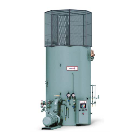
- Page 1 Electrode Boiler Model CEJS Installation, Operation, and Maintenance 750-272 11/2015...
- Page 2 WARNING ! DANGER DO NOT OPERATE, SERVICE, OR REPAIR THIS EQUIPMENT UNLESS YOU FULLY UNDERSTAND ALL APPLICABLE SECTIONS OF THIS MANUAL. DO NOT ALLOW OTHERS TO OPERATE, SERVICE, OR REPAIR THIS EQUIPMENT UNLESS THEY FULLY UNDERSTAND ALL APPLICABLE SECTIONS OF THIS MANUAL. FAILURE TO FOLLOW ALL APPLICABLE WARNINGS AND INSTRUCTIONS MAY RESULT IN SEVERE PERSONAL INJURY OR DEATH.
-
Page 3: Table Of Contents
CONTENTS Introduction 1 Description 1 Operating principles 1 Advantages/performance benefits 3 Installation 3 Location 3 Piping 4 Mechanical 8 Electrical 9 Water Treatment 11 Electrical Systems 12 High voltage power supply 12 Medium voltage power supply 13 120V Boiler control circuits 13 Water Level Control Systems 15 Before Startup 15 Boiler Cleanout 15... -
Page 5: Introduction
Brooks Electrode Steam Boiler Model CEJS. The CEJS is a three-phase four-wire high voltage steam- producing boiler with automatic control and limiting functions. 1.1-Description The CEJS Electrode Steam Boiler is several systems integrated into a single unit to function as a heating system. The several systems making up the boiler are: • The electrodes •... - Page 6 Electrode Boiler electrode and drains through the nozzle plate (5) which forms the bottom of the electrode. As the water falls from the electrode, it strikes the counter electrode (6) and a second current path R2 is established. Since both the nozzle stock and the counter electrode are in contact with the boiler shell, they form the common connection points of a ''Y”...
-
Page 7: Advantages/Performance Benefits
There will be no heat buildup in the electrodes, no electrode burnout, and no danger to the boiler itself. The efficient utilization of electrical energy enables the CEJS to provide a very high steam output within a small physical space. -
Page 8: Piping
For field installed piping refer to Figure 3 and the piping schematic for your boiler. Install all piping shown by dotted lines and all piping external to the boiler package. Components normally included as standard with CEJS boilers are described below. Note: Different piping configurations are possible depending on boiler capacity. The diagram shows a typical application. - Page 9 Electrode Boiler Figure 3 - Typical piping configuration 750-272...
- Page 10 Electrode Boiler Fe e d w a t e r a n d w a t e r l e v e l controller Regulating Valve Feedwater is piped into the boiler near the base of the pressure Check Valve Strainer vessel.
- Page 11 Electrode Boiler Sampling system and surface blowdown The piping schematic will show the specific details of these lines. The most common configuration of the sample line is a gate valve at the vessel, a sample cooler, and sometimes a flow control metering valve to a fitting holding the conductivity cell.
-
Page 12: Mechanical
Electrode Boiler 2.3-Mechanical Circulation pump The circulation pump is a pre-assembled unit. Installation consists of bolting it in the mounting flange with gaskets and tightening the bolts on the discharge manifold and pump flange. The pump contains a mechanical seal which in some installations may require the connection of a cooling water inlet and drain. -
Page 13: Electrical
Electrode Boiler The hydraulic pump should be conveniently located for service access and piping run to the hydraulic cylinder. Hydraulic The regulating shield is positioned by the hydraulic system. Cylinder There are two hydraulic lines from the flow control valves on the hydraulic pump to the hydraulic cylinder mounted on top of the boiler. - Page 14 Electrode Boiler POWER UNIT STARTUP 1. To properly perform the dual function of lubrication and transmission of power, we recommend the use of a good quality SAE 10 Grade Hydraulic Oil for systems having an operating temperature range from 0 deg F minimum to 160 deg F maximum, or an SAE 20 Grade Hydraulic Oil for 32 deg F Minimum to 200 deg F maximum temperature range.
-
Page 15: Water Treatment
Electrode Boiler 3 - Water Treatment The KW output of the boiler is determined by the conductivity of the water in the system. Water conductivity is determined by its chemical makeup. General water hardness, pH, alkalinity, iron, oxygen, and total dissolved solids all have an effect on boiler operation. The water required for CB boilers should be non-scale forming, non-corrosive, non-foaming, and should have the following chemical characteristics: •... -
Page 16: Electrical Systems
Electrode Boiler Caution Before any water treatment program is implemented, a complete water analysis should be provided to Cleaver-Brooks for review. 4 - Electrical Systems The three electrical systems are described in this section, which gives a general outline of the basic circuits and their functions. -
Page 17: Medium Voltage Power Supply
4.3-120V Boiler control circuits The control circuits oversee the automatic functioning of the boiler during normal operation. The control circuits are briefly described in the following section as they typically appear in a standard CEJS boiler. Actual configuration may vary. - Page 18 Electrode Boiler High voltage feedback circuit This circuit shows whether the high voltage circuit breaker is open or closed by lighting either the "HIGH VOLTAGE ON" or "OFF" light on the boiler control panel. It also performs an ancillary control logic function (see control wiring schematic).
-
Page 19: Water Level Control Systems
Electrode Boiler 5 - Water Level Control Systems CB electrode high voltage steam boilers are designed to operate with constant water levels. During operation, feedwater must be added to compensate for steam production and surface blowdown. A modulating valve is used to admit feedwater to the boiler in proportion to the rate of water consumption. -
Page 20: Water Test
Electrode Boiler Important CB will not be responsible for damage incurred at startup unless the preceding precautions are taken. 6.2-Water Test Verify correct positioning and alignment of jets by running the circulation pump and observing jet shapes. Check for excessive splashing at the top of stroke; optional splash guards may be installed. Eliminate any leaks or spraying. -
Page 21: Boiler Controls
Electrode Boiler 7 - Boiler Controls CEJS boilers feature an integral control panel housing the PLC -based control system components and the touchscreen HMI. The HMI screens are described below. 7.1- Main Menu The Main Menu appears on power-up. This... -
Page 22: Hv Data
Electrode Boiler 7.3-HV Data The HV Data screen monitors the boiler's 3- phase high voltage power via the power meter. This screen shows the real-time voltages and currents for each phase (including current to neutral) along with the frequency and voltage/ current imbalances. -
Page 23: Water Level Pid
Electrode Boiler 7.6-Water Level PID The Water Level PID screen allows for the setting of the system setpoints controlling Proportional, Integral, and Derivative values (password-protected). The user must be logged in to access the Manual operations. While in manual mode, the user can use the "CV" button to enter a value for the PID loop output to manually control the valve. -
Page 24: Alarm
Electrode Boiler 7.8-Alarm The Alarm screen is used to acknowledge alarms. Once acknowledged, an alarm may be cleared from the Alarm History screen. When acknowledging an alarm, investigate and correct the cause of the alarm before re-starting the boiler. 7.9-Alarm History The Alarm History screen displays a record of alarms logged by the system with a date/time stamp and brief description for each. -
Page 25: General Configuration
Electrode Boiler 7.10-General Configuration The General Configuration screen contains general information about the boiler in addition to contact information for the local Cleaver Brooks representative. The user must be logged on to change these values. 7.11-Networking Configuration The Networking configuration screen allows the user to set the IP address for the HMI and allows for the option of automatic alarm notifications via e-mail. -
Page 26: Operating Setpoints Configuration
Electrode Boiler 7.12-Operating Setpoints Configuration The Operating Setpoints configuration screen allows the user to enter specific setpoints for normal boiler operations. The remote pressure and power limit setpoints as well as the power limit and scaling factors can be set/enabled from this screen. - Page 27 Electrode Boiler • Operating Press Deadband (psi) Defines the deadband range (psi) to eliminate shield "hunting" when the pressure does not exactly match the operating pressure setpoint. • Column BD Timer (sec) Defines the time that the level alarms and associated feedback are disabled during a blowdown sequence.
- Page 28 Electrode Boiler 7.12b - Factory Settings The Factory Settings configuration screen allows the setting of crutial setpoints during the initial startup of the boiler. These setpoints are typically determined at startup and are not changed in the normal course of boiler operation. These parameters are set by Cleaver Brooks and should only be changed by qualified and authorized personnel.
- Page 29 Electrode Boiler • Shield Pulse Off Time (sec) Defines the amount of time the hydraulic shield contactor remains de-energized (Off) during the shield pulse. • Shield Pulse On Time (sec) Defines the amount of time the hydraulic shield contactor remains energized (On) during the shield pulse.
- Page 30 Electrode Boiler • Water Level Switches (%) (cont.) LSH: High water limit which triggers the high water alarm. LSHH: High-High water limit which triggers the high water boiler shutdown and opening of the HW breaker. • LSH Time Delay (sec) Defines the amount of time delay between the triggering of the high water limit (LSH) and the sounding of the high water alarm to alleviate momentary or nuisance trips.
-
Page 31: Schedule
Electrode Boiler 7.12d - Power Calculation The Power Calculation screen allows for the scaling of the raw power reading from the power meter by adjusting scaling parameters to produce t h e d e s i r e d s c a l e d p o w e r v a l u e . T h e s e parameters are set by Cleaver Brooks and should only be changed by qualified and authorized personnel. -
Page 32: Startup And Operation
Electrode Boiler 8 - Startup and Operation When starting the CEJS boiler for the first time, observe the deaerator or condensate tank, sight glass, and chemical feed pump to monitor their performance until the control systems have been tested. After the pressure is up for the first time, check the safety valve operation and settings. -
Page 33: Startup (Automatic Mode)
Electrode Boiler 6.Lower shield at a maximum rate of 5% increments approximately every 5 minutes. Continue this process until the boiler pressure reaches 100 psig. When the steam pressure reaches 40 psi, close the manual air vent. The boiler pressure will need to exceed the level required to open the back pressure valve, and be slightly above the pressure in the steam main, before the boiler will begin to feed steam into the system. -
Page 34: Standby And Shutdown
The PLC may be turned off using the control power switch on the panel. 8.6-Normal operation The CEJS boiler has completely automatic operating controls, feedback, and limiting functions. The only attention it will need during normal operation is a periodic check of the ammeter. The "POWER LIMIT"... -
Page 35: Maintenance
Electrode Boiler 9 - Maintenance Since the boiler 's operation is usually supervised by its automatic controls, conscientious preventative maintenance should be practiced at all times. Keep the electrical circuitry clean and dry, and all contacts tight, especially on the magnetic contactors. Do not allow dust or dampness to accumulate anywhere in the control cabinet. -
Page 36: Daily Maintenance
Electrode Boiler 9.2-Daily maintenance 1.Clean the strainers in the water supply, cooling, feedwater pump, and blowdown cooling lines. 2.Check each open valve for freedom of operation. 3.Blow down the water column by opening the drain on the bottom. Allow two to ten seconds for blow- down, then close the valve fully. -
Page 37: Monthly Maintenance
Electrode Boiler 9.3-Monthly maintenance 1.Shut the boiler down and turn off the power supply. Check all electrical connections for tightness. Be particularly careful during the first few months of service. Check contacts for discoloration, corrosion, or pitting. 2.Make an instantaneous check of the safety valves. Allow them to slam shut to ensure good seating. 3.Check the elements of the standby heater with a megohmmeter. -
Page 38: Replacement Of Porcelain Insulators
Electrode Boiler 9.5-Replacement of porcelain insulators 1.Turn off all power to the boiler, drain the pressure vessel completely, and allow it to cool. Boiler should not be heated/cooled quicker than 3-5 F per minute to protect the porcelain insulators from damage. - Page 39 Electrode Boiler Lower Electrode Assembly 1. Electrode Housing 2. Copper Gasket (Triangular) 3. Electrode Bracket 4. Copper Gasket (Round) 5. Bracket Adapter* 6. Electrode Rod* 7. Graphite Gasket 8. Sponge Gasket 2-1/2” x 1-3/4” 9. Lower Centering Ring 10. Sponge Gasket 2-1/2” x 1-3/4” 11.
- Page 40 Electrode Boiler Electrode Installation • Install lifting eye-hook onto electrode shaft. • Hoist the completed lower electrode assembly up through the boiler 's electrode fitting. Hoisting procedure will require careful handling of electrode by workers inside the boiler. Eye-hook Adapter Electrode rod •...
- Page 41 Electrode Boiler Upper Electrode Assembly 1. Graphite Gasket 2. Porcelain Insulator 3. Sponge Gasket 2-1/2” x 1-3/4” 4. Graphite Gasket 5. Upper Centering Ring 6. Spring Washers (see Figure 13 on pg. 38) 7. Spacer 8. Bearing 9. Retaining Nut Caution Check for required space between quartz and top of...
- Page 42 Electrode Boiler Electrode positioning • Space and center each of the electrode housings. The bottom plate of the electrode bracket is fitted with slots for front-back adjusting. Verify the electrode housing is squarely facing the nozzle plates. • Tighten electrode retaining nut until washers are compressed to the appropriate specifications as shown below in Figure 13.
- Page 43 Electrode Boiler Electrode positioning (continued) • Measure and adjust distance between bottom of electrode boxes and counter electrodes. • Measure and adjust the distance from each electrode box to the center water column nozzle plates. Each electrode box should be aligned perfectly parallel to the center column to ensure to the nozzle openings align precisely with the target plates.
-
Page 44: Packing Of Gland Housing Assembly For Control Rod
Electrode Boiler 9.6-Packing of gland housing assembly for control rod The control rod gland housing packing must be replaced/repaired once a steam leak is realized. The packing can be tightened without completely replacing all material every time. Refer to the steps below for details to ensure the gland housing is properly packed and to minimize the risk associated with improper packing techniques. -
Page 45: Layup
Electrode Boiler 10 - Layup At times it is desirable to shut the boiler down for an extended period ("Layup"). The preparation method used depends on the duration of layup and on how much time it is convenient to take in placing the boiler back into service. - Page 46 Web Address: http://www.cleaverbrooks.com...
Need help?
Do you have a question about the CEJS and is the answer not in the manual?
Questions and answers