Advertisement
Advertisement
Table of Contents

Related Manuals for FAAC E024 U


Summary of Contents for FAAC E024 U
- Page 1 E024 U Control Board FAAC International Inc. FAAC International Inc. West Coast Operations Headquarter & East Coast Operations 357 South Acacia Avenue 5151 Sunbeam Road Unit 357 Suites 9-11 Fullerton, CA 92831 Jacksonville, FL 32257 Tel. 800 221 8278 Tel. 866 925 3222...
-
Page 2: Technical Specifications
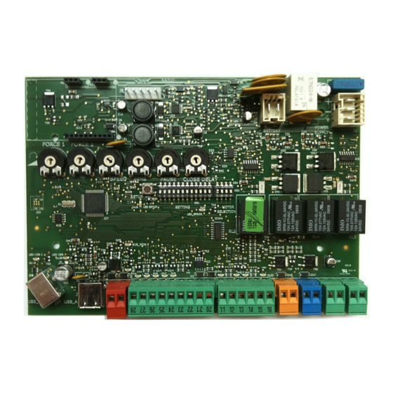
SETTING DL 1 DL 2 DL 3 DL 4 DL 5 1 TECHNICAL SPECIFICATIONS 2 LAYOUT AND COMPONENTS Main power supply 230/115 V~ 50/60 Hz switchable RADIO Connector for the radio receiver Secondary power 24 Vdc - 16 A max. BATTERY Connector for the backup battery (min. -
Page 3: Input / Output Description
3 INPUT / OUTPUT DESCRIPTION B STP CL OP OPEN LABEL FUNCTION 2 EASY 2 EASY Input for bus 2easy accessories (encoder) OPEN A N.O. Contact for total opening command OPEN B / OPEN B: N.O. Contact for opening of leaf 1 only CLOSE CLOSE (LOGIC B-C): N.O. - Page 4 4 PHOTOCELLS CONNECTIONS Ho to put together Normally Close connections. ( Connect them in series) Ho to put together Normally Open connections. ( Connect them in parallel) Fig. 7 Fig. 6 The E024U board allows the connection of several safety devices (for example photocells).
- Page 5 Connection of two pairs of closing photocells STP CL OP Other optional safety devices to connect in series RX= Photocell Receiver TX= Ptotocell Transmitter CL= Closing OP= Opening Fig. 10 To use the FAIL-SAFE mode connect the negative power supply of the transmitters to OUT (pin 9), and set dip- switch 11 and 12 to ON on DS1 When using the FAIL-SAFE mode also the safety inputs not used (FSW CL , FSW OP) must be connected to OUT (pin No.
- Page 6 Connection of a pair of closing photocells and a pair of opening photocells STP CL OP RX= Photocell Receiver TX= Ptotocell Transmitter CL= Closing OP= Opening Fig. 12 To use the FAIL-SAFE mode connect the negative power supply of the transmitters to OUT (pin 9), and set dip- switch 11 and 12 to ON on DS1 Connection of no safety or stop devices (NOT RECOMMENDED) Connection of one pair of opening photocells...
- Page 7 5 PROGRAMMING 5.1 ADJUSTING TRIMMERS TR1 – FORCE ADJUSTMENT MOTOR 1 Turn clockwise to increase the opening and closing force TR 2 – FORCE ADJUSTEMENT MOTOR 2 Turn clockwise to increase the opening and closing force TR 3 – SPEED ADJUSTMENT FOR MOTOR1 AND MOTOR 2 Turn clockwise to increase the opening and closing speed TR 4 –...
-
Page 8: Operating Logic
5.2 DIP SWITCH SETTINGS DS1 SW1,SW2,SW3 : OPERATING LOGIC OPERATING LOGIC DS 1 : SW 1 - SW 2 - SW 3 PAUSE LOGIC SW 1 SW 2 SW 3 DESCRIPTION TIME E (default) One command opens, the next one closes Semiautomatic 0 - 4 One command opens, waits for the pause time an then... - Page 9 5.3 DIP SWITCH DS1 SW4...SW12: BOARD SETUP DS 1 SETTINGS SW 4 to SW 12 The opening of leaf 2 is delayed after the opening of leaf 1. This is OPENING DELAY SW 4 to avoid that the gate’s leafs interfere with each other during the 0 sec (default) initial part of the movement.
-
Page 10: Very Important
S450H, S700H (from gate closed) S418 Active always except 3 sec. before an 412, 413, 415, 390, 770 opening NON FAAC 6 DIAGNOSTIC DS 2 DS 1 SETTING BUS DEVICE DL 1 DL 2 DL 3 DL 4 DL 5... - Page 11 LEDS DIAGNOSTIC ( Tab. X ) LED STATUS In BOLD the normal state with gate closed and working DESCRIPTION ON STEADY BLINKING Board working on Board working on AC LED BATTERY battery power or ext power Battery low supply LED +24 Main power present Main power OFF SLOW BLINK...
-
Page 12: Time Learning ( Set-Up)
The diagnostic LED shows only one error condition at a time, with the priority of the below table. In case there are more then one error once one is eliminated the LED will show the next TABLE 4: LED ERROR DISPLAY NUMBER OF ERROR CONDITION SOLUTION... - Page 13 present) starts moving slowly. The LED will blink during all the setup procedure 2. The leaf 2 will move in closing direction until it reaches the mechanical stop or FCC2 3. The leaf 1 starts moving slowly until it reaches the mechanical stop or FCC1 4.
- Page 14 8 Enclosure 9 AC power connection The E024U board is supplied on a panel that fits in a AC POWER GUIDELINES: standard 16x10” enclosure. THE E024U control board and power supply uses a single phase AC power line to operate, charge the batteries, and power gate accessories.
-
Page 15: Power Supply
10 POWER SUPPLY 11.1 DISABLE BATTERY CHARGING The E024U board is powered by a high efficiency To disable the battery charging unplug jumper J24 switching power supply that take 115V or 230V in input and provides 36VDC to power the board. J24 PRESENT=BATTERY CHARGING ACTIVE Before turning the power ON you have to select the J24 NOT PRESENT= BATTERY CHARGING NOT ACTIVE... -
Page 16: Function Logics
FUNCTION LOGICS LOGIC “E” PULSES SYSTEM STATUS OPEN A OPEN B CLOSE STOP FSW OP FSW CL FSW CL/OP no effect no effect no effect CLOSED opens the leaves opens leaf 1 no effect no effect (OPEN disa- (OPEN disabled) (OPEN disabled) bled) stops and opens... - Page 17 LOGIC “EP” PULSES SYSTEM STATUS OPEN A OPEN B CLOSE STOP FSW OP FSW CL FSW CL/OP no effect no effect no effect CLOSED opens the leaves opens leaf 1 no effect no effect (OPEN disabled) (OPEN disabled) (OPEN disabled) stops and opens recloses immediately...
- Page 18 For the upgrade you need a USB Flash Drive, where The E024U board keeps the operating firmware in a field you have to copy the file supplied by FAAC. Then follow programmable memory, that can be easily upgraded. these steps: WARNING: Only upgrade the firmware with the proper file supplied by FAAC.
Need help?
Do you have a question about the E024 U and is the answer not in the manual?
Questions and answers