Table of Contents
Advertisement
Quick Links
Advertisement
Table of Contents

Subscribe to Our Youtube Channel
Related Manuals for Dell EMC S5048F-ON


Summary of Contents for Dell EMC S5048F-ON
- Page 1 S5048F-ON Installation Guide October 2017...
- Page 2 Notes, cautions, and warnings NOTE: A NOTE indicates important information that helps you make better use of your product. CAUTION: A CAUTION indicates either potential damage to hardware or loss of data and tells you how to avoid the problem. WARNING: A WARNING indicates a potential for property damage, personal injury, or death.
-
Page 3: Table Of Contents
Rack mounting.................................. 15 Switch ground................................... 15 Fans and airflow................................15 Fan combinations................................15 Power....................................15 Storing components................................. 16 4 S5048F-ON switch installation........................17 Unpack....................................17 Unpacking Steps................................. 17 Rack or cabinet hardware installation..........................18 Rack mount safety considerations........................... 18 ReadyRails installation..............................18 Tool-less square-hole installation.......................... - Page 4 Safety standards and compliance agency certifications..................... 43 Electromagnetic compatibility............................43 Emissions..................................43 Immunity..................................43 Product recycling and disposal............................44 Waste electrical and electronic equipment (WEEE) directive for recovery, recycle and reuse of IT and telecommunications products..........................44 9 Dell EMC support............................45 Contents...
-
Page 5: About This Guide
When no cable is connected, visible and invisible laser radiation may emit from the aperture of the optical transceiver ports. Avoid exposure to laser radiation. Do not stare into open apertures. Regulatory Marketing model S5048F-ON is represented by the regulatory model E21W and the regulatory type E21W004. Topics: •... -
Page 6: Information Symbols
Information symbols This book uses the following information symbols: NOTE: The Note icon signals important operational information. CAUTION: The Caution icon signals information about situations that could result in equipment damage or loss of data. WARNING: The Warning icon signals information about hardware handling that could result in injury. WARNING: The ESD Warning icon requires that you take electrostatic precautions when handling the device. -
Page 7: S5048F-On Switch
LED Status Icons The S5048F-ON switch has one RJ-45 serial console port, one Micro-USB type-B console port, one 10/100/1000 Base-T Ethernet management port, and one USB type-A port for the external storage. Management ports are located on the PSU-side of the switch. -
Page 8: Features
• PSU/fan tray handle: 1.57 inches (40 mm) LED display The S5048F-ON switch includes LED displays on the I/O side of the switch. NOTE: If you are installing third-party software, for LED information, see your third-party operating software (OS) documentation. -
Page 9: Led Behavior
LED behavior The following S5048F-ON switch LED behavior is seen during open networking installation environment (ONIE) operations: Figure 4. S5048F-ON LEDs Stack ID LED SFP28 Port Link/Activity LED QSFP28 Port Link/Activity LED Master LED System LED Locator LED Fan LED Power LED RJ-45 Ethernet Port LED: Left is activity;... - Page 10 Description Link LED • Off—No link • Solid green—Link operating at a maximum speed, autonegotiated/forced or 1G • Solid yellow—Link operating at a lower speed, autonegotiated/ forced or 10/100M Activity LED • Off—No link • Flashing green—Port activity S5048F-ON switch...
-
Page 11: Prerequisites
Site preparations S5048F-ON switch installation. • S5048F-ON switch or multiple switches, if stacking • AC or DC country- and regional-specific cables to connect the AC or DC power source to each of the switches’ AC or DC power supplies •... -
Page 12: S5048F-On Switch Configurations
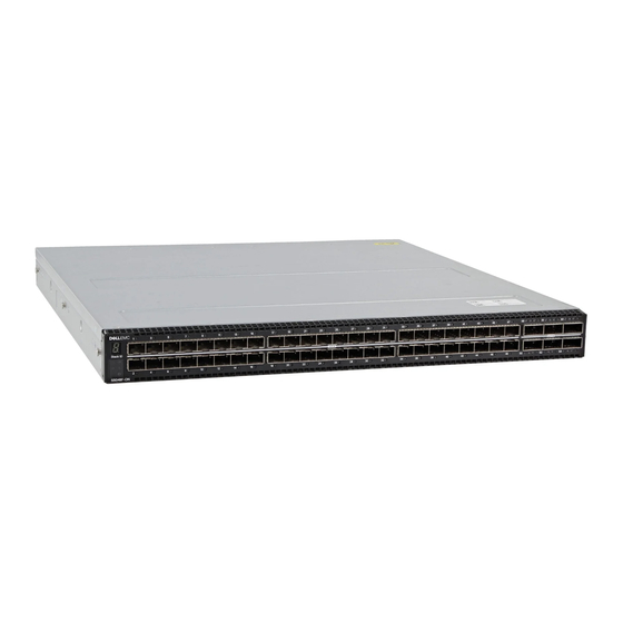
You can order the S5048F-ON switch in several different configurations. • S5048F-ON AC or DC Normal Airflow: 54 Ethernet ports—48 SFP28 1/10/25GbE ports and 6 QSFP28 4x10/4x25/40/100GbE ports —two AC or DC power supplies, and four fan subsystems with airflow from the I/O side to the power supply side •... - Page 13 Figure 5. S5048F-ON switch luggage tag Service tag MAC address PPID Express service code S5048F-ON switch...
-
Page 14: Site Preparations
Site preparations The S5048F-ON switch is suitable for installation as part of a common bond network (CBN). You can install the switch in: • Network telecommunication facilities • Data centers • Other locations where the National Electric Code (NEC) applies For more information about switch specifications, see Specifications. -
Page 15: Rack Mounting
The S5048F-ON switch fans support two airflow options: normal and reverse. Fan combinations Fan installation is done as part of the factory install based on stock keeping unit (SKU) type. The S5048F-ON switch has SKUs that support the following configurations: •... -
Page 16: Storing Components
Storing components If you do not install your S5048F-ON switch and components immediately, properly store the switch and all optional components using these guidelines: • Storage location temperature must remain constant. The storage range is from -40°C to 70°C (-40°F to 158°F). -
Page 17: S5048F-On Switch Installation
ESD damage can occur if components are mishandled. Always wear an ESD-preventive wrist or heel ground strap when handling the S5048F-ON switch and components. As with all electrical devices of this type, take all the necessary safety precautions to prevent injury when installing this switch. -
Page 18: Rack Or Cabinet Hardware Installation
ReadyRails installation To easily configure your rack for installation of your S5048F-ON switch, use the ReadyRails rack mounting system provided. You can install the ReadyRails system using the 1U tool-less method or one of three possible 1U tooled methods—two-post flush mount, two-post center mount, or four-post threaded mount. -
Page 19: Tool-Less Square-Hole Installation
With the ReadyRails flange ears facing outward, place one rail between the left and right vertical posts. Align and seat the back flange rail pegs in the back vertical post flange. The following shows how the pegs appear in both the square and nonthreaded round holes: S5048F-ON switch installation... -
Page 20: Two-Post Flush-Mount Installation
For this configuration, remove the castings from the front side of each ReadyRails assembly, see item 1. Use a Torx screwdriver to remove the two screws from each front latch on the switch side of the rail. Remove the tool-less latch casting. Retain the castings for future rack requirements. Do not remove the back latch castings. S5048F-ON switch installation... -
Page 21: Two-Post Center-Mount Installation
For more installation instructions, see the installation labels attached to the rail assembly. Slide the plunger bracket rearward until it clicks into place and secure the bracket to the front post flange with two user-supplied screws. See item 1. S5048F-ON switch installation... -
Page 22: Four-Post Threaded Installation
For this installation, remove the tool-less latch castings from the front side of each ReadyRails assembly. See item 1. Use a Torx screwdriver to remove the two screws from each front latch on the switch side of the rail. Remove the tool-less latch casting. Retain the castings for future rack requirements. S5048F-ON switch installation... -
Page 23: Switch Installation
NOTE: For more instructions, see the installation instruction labels on the rail. Attach the inner switch rails to the S5048F-ON switch. Line up the rail with the mounting heads and attach the rail to the switch. Slide the rail back until it locks into place. The following shows the detail of the front standoff with the locking tab:... - Page 24 After installing both switch rails, line them up on the previously mounted ReadyRails and slide the switch in until it is flush with front of rack. To keep the switch from inadvertently sliding out of the rack and falling, about 3 inches before you fully insert your switch, the rail locking feature engages. S5048F-ON switch installation...
-
Page 25: Ground Cable
Two threaded holes using one of the two included M4 screws. In both configurations, the ground cable is not included. To properly ground the switch, Dell EMC recommends a one- or two-hole lug, M3 or M4 hole size. The ground lugs must be a UL-recognized, crimp-type lug. -
Page 26: Optics Installation
Do not jerk or tug repeatedly on the tab. Switch power-up Supply power to the S5048F-ON switch after it is mounted in a rack or cabinet. Dell EMC recommends reinspecting your switch before powering it up. Verify the following: •... -
Page 27: Power Up Sequence
When the switch powers up, the fans immediately come on at high speed. The fan speed slows as the switch continues to boot up. After switch placement To configure your switch, after you have securely installed and powered on the S5048F-ON switch, see your open network installation environment (ONIE)-compatible operating system documentation at www.onie.org. For more information about working with the ONIE environment, see your switch documentation at www.dell.com/support. -
Page 28: Power Supplies
Power supplies The S5048F-ON switch ships with two AC or DC power supplies. The two power supplies have two air-flow directions—from the I/O to the PSU and from the PSU to the I/O. Two PSUs are required for full redundancy, but the switch can operate with a single PSU. -
Page 29: Psu Leds
1—PSU installation Plug in the appropriate AC 3-prongs cord from the switch PSU to the external power source. Repeat steps 1 through 4 if you have a redundant PSU using the second PSU slot on the S5048F-ON switch. Power supplies... -
Page 30: Ac Or Dc Power Supply Replacement
NOTE: The S5048F-ON switch powers up when you connect the cables between the power supply and the power source. AC or DC power supply replacement CAUTION: Disconnect the power cord before removing the power supplies. Also, disconnect all power cords before servicing. - Page 31 Strip 0.5 inches of insulation from each of the power connector’s wires, RTN and –48V, as shown. Insert each of the power connector’s bare wire lengths into the wiring block. Insert RTN into one hole and –48V into the other hole, as shown.
-
Page 32: Fans
Fans The S5048F-ON switch comes from the factory with two PSUs and four fan modules installed in the switch. The fan modules and the power supplies, which have integrated fans, are hot-swappable. In addition to the power supply modules, you can order and install fan modules separately. -
Page 33: Fan Leds
• Off—Fan is off. Fan module installation The fan modules in the S5048F-ON switch are field replaceable. Module slot 1 is on the left side of the switch; module slot 4 is on the right side of the switch. CAUTION: DO NOT mix airflow directions. -
Page 34: Management Ports
Management ports Besides the 10/100/1000Base-T RJ-45 ports, the S5048F-ON switch provides several ports for management and storage. NOTE: The output examples in this section are for reference only. Your output may vary. Topics: • RS-232 console port access • MicroUSB-B console port access •... -
Page 35: Microusb-B Console Port Access
• No flow control MicroUSB-B console port access The MicroUSB-B console port is on the PSU side of the S5048F-ON switch. The terminal settings are the same for the serial console port and the RS-232/RJ-45 console port: • 115200 baud rate •... -
Page 36: Before You Install An Os
Before you install an OS After powering on the S5048F-ON switch, it goes through a power-on self-test (POST). POST runs every time the switch is initialized and checks the hardware components to determine if the switch is fully operational before booting. -
Page 37: Check Your Switch
NOTE: For more information, see the NOTE: After you have securely installed and powered on the S5048F-ON switch, to configure your switch, see your third-party ONIE-compatible OS or the Dell EMC OS documentation. Check your switch To confirm that ONIE is working properly, use the onie-sysinfo command. Run the onie-sysinfo command at the ONIE prompt. - Page 38 You can install an operating system manually from HTTP, FTP, or TFTP using the onie-nos-install <URL> command. NOTE: If you have a recovery USB plugged into your switch, you must remove it before installing the DIAG-OS using the onie- nos-install command. The ONIE Install environment uses DHCP to assign an IP address to the management interface—eth0.
-
Page 39: Specifications
Specifications This section lists the S5048F-ON switch specifications. CAUTION: Operate the product at an ambient temperature not higher than 113°F (45°C). CAUTION: Lithium Battery Caution: There is a danger of explosion if the battery is incorrectly replaced. Replace only with same or equivalent type of battery. -
Page 40: Ieee Standards
−40.5, -48V, –60V Input power at full load -40.5/500W, -48V/500W, -60V/500W Input current at full load -40.5V/12.35A, -48V/10.42A, -60V/8.33A IEEE standards The S5048F-ON switch complies with the following IEEE standards. • 802.1ab (LLDP) • 802.1ax (Layer 2) • 802.1d, 802.1w, 802.1s, 802.1x (Mgmt/Security), 802.3x (Layer 2) •... -
Page 41: Agency Compliance
Properly shielded and grounded cables and connectors must be used in order to meet FCC emission limits. Dell EMC is not responsible for any radio or television interference caused by using other than recommended cables and connectors or by unauthorized changes or modifications in the equipment. -
Page 42: Japan Vcci Compliance For Class A Equipment
(VCCI). If this equipment is used in a domestic environment, radio disturbance may arise. When such trouble occurs, the user may be required to take corrective actions. WARNING: Use the AC power cords with Dell EMC equipment only. Do not use Dell EMC AC power cords with any unauthorized hardware. Figure 21. Japan: warning label Korean certification of compliance Figure 22. -
Page 43: Safety Standards And Compliance Agency Certifications
Figure 23. Korean package label Safety standards and compliance agency certifications • CUS UL 60950-1, 2nd Edition • CSA 60950-1-03, 2nd Edition • EN 60950-1, 2nd Edition • EN 60825-1, 1st Edition • EN 60825-1 Safety of Laser Products—Part 1: Equipment Classification Requirements and User’s Guide •... -
Page 44: Product Recycling And Disposal
You must recycle or discard this switch according to applicable local and national regulations. Dell EMC encourages owners of information technology (IT) equipment to responsibly recycle their equipment when it is no longer needed. Dell EMC offers a variety of product return programs and services in several countries to assist equipment owners in recycling their IT products. -
Page 45: Dell Emc Support
The Dell EMC support site provides integrated, secure access to these services. To access the Dell EMC support site, go to www.dell.com/support/. To display information in your language, scroll down to the bottom of the web page and select your country from the drop-down menu.
Need help?
Do you have a question about the S5048F-ON and is the answer not in the manual?
Questions and answers