Table of Contents
Advertisement
Quick Links
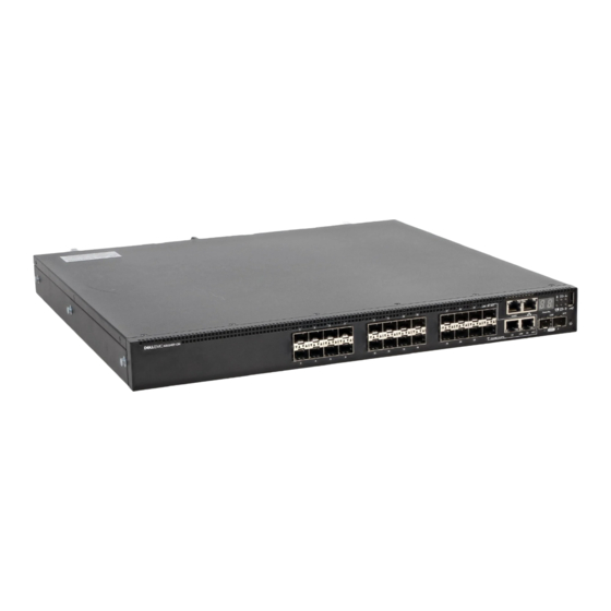
- 1 N3000Et-On/N3000Ep-On Hardware Overview
- 2 Power Consumption and Power Budget for the N3024Ep-On and N3048Ep-On Poe Switches
- 3 Starting and Configuring the N3000Et-On/N3000Ep-On Switch
- 4 Connecting an N3000Et-On/N3000Ep-On Switch to a Terminal
- 5 Performing the N3000Et-On/N3000Ep-On Initial Configuration
- 6 Enabling Remote Management
- Download this manual
Advertisement
Table of Contents


Need help?
Do you have a question about the N3024ET-ON and is the answer not in the manual?
Questions and answers