
Subscribe to Our Youtube Channel
Related Manuals for Lindab FDS-M


Summary of Contents for Lindab FDS-M
- Page 1 | we si mpli fy c onst r uction Lindab Fire Damper Steering System User manual Version 1.2 - August 2018...
-
Page 2: Table Of Contents
Click on the text or the page to go to the related section of the manual. 1. Description of the system ....... 3 2. Components 2.1 FDS-M Master unit ..........5 2.2 FDS-S Slave unit ........... 6 3. Installation (up to 4 dampers) - no slave 3.1 Power supply to main unit ........ -
Page 3: Description Of The System
The Fire Damper System (FDS) allows to feed, monitor and test up to 60 fire dampers. Smoke detectors can be con- nected and monitored, as well. The system is designed to feed only 24V fire dampers. The system is composed of: FDS-M FDS-S FDS-P... -
Page 4: Components
300 m. Four fire dampers and four detector smoke detectors can be connected directly (locally) to FDS-M. FDS-RB WH/WK FDS-DD/FDS-CD Relay module Fire dampers Smoke detectors Relay module used for:... -
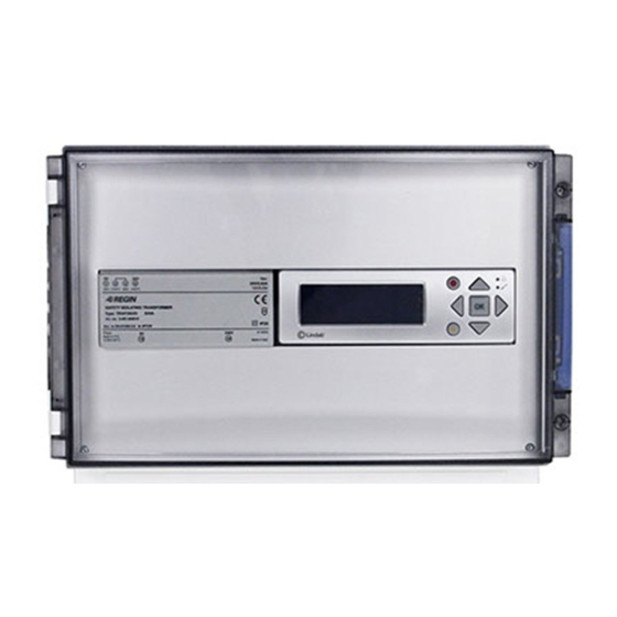
Page 5: Fds-M Master Unit
7. Red button: Takes to the alarm acknowledgment page 8. C button: exit value editing The PCB at the bottom of the unit allows to easily wire components with no need to open the FDS-M box. STOP AHU ALARM PRESSURE 0-10 V... -
Page 6: Fds-S Slave Unit
2.2 FDS-S Slave unit FDS-S slave unit is a module controlled by hidden pushbuttons together with one LED. Steady green: unit is addressed and working. No alarm reported. Steady orange: service alarm (communication or dirty smoke detector) Steady red: A (fire) alarm Fig. -
Page 7: Installation (Up To 4 Dampers) - No Slave 3.1 Power Supply To Main Unit
Fuse 6,3A FDS-M 3.2 Connect local fire dampers (up to 4) Connect local fire dampers power supply and position switches to master unit. Maximum 4 fire dampers could be connected directly to the master unit (FDS-M). Fire damper 1 FDS-M S2_1... -
Page 8: Connect Local Smoke Detectors (Up To 4)
3.3 Connect local smoke detectors (up to 4) Fire damper 1 Fire damper 1 Connect local smoke detectors to master unit. Maximum 4 smoke detectors could be connected directly to the master unit (FDS-M). Fire damper 2 Fire damper 2 Fire damper 2... -
Page 9: Connect Slave Unit To Master Unit And First Power Supply
If in the system there are slave unit (FDS-S) the first slave must be supplied with power supply unit (FDS-P). 4.1 Connect slave unit to master unit and first power supply - Provide 230 V power supply to FDS-M as described in point 3.1 p. 7 - Provide 230 V power supply to transformer FDS-P... -
Page 10: Connect Fire Damper To Slave Unit
FDS-S FDS-S 4.2 Connect fire damper to slave unit One fire damper per slave unit is allowed. Communication (4 input) smoke (2 input) 24 V FDS-S 1 2 3 4 5 6 7 8 Fire damper Duct smoke detector Ceiling smoke detector FDS-S FDS-S 2,2 k... -
Page 11: Connect Smoke Detector To Slave Unit
Fire damper Fire damper 4.3 Connect smoke detector to slave unit One smoke detector per slave unit is allowed. Ceiling smoke detector Ceiling smoke detector Duct smoke detector Duct smoke detector FDS-S FDS-S FDS-S FDS-S 2,2 k Ω 2,2 k Ω... -
Page 12: Connect Slave Unit To Slave Unit
230 V 230 V 230 V Fire damper 230 V 230 VAC 230 VAC 230 VAC 24 VAC 24 VAC 24 VAC FDS-M Max 300m Max 300m FDS-R G G0 G G0 G G0 G G0 G G0 G G0 FDS-S... - Page 13 Supply cable sizing The wire size of the supply cable can be determined by calculating the resistance pr meter R. The calculation presupposes that a voltage drop of e.g. 2V is accepted in the supply cable: R(per m) = U drop / (I * L) [Ω/m] where: U drop is the accepted voltage drop (2V) in the cable [V] I is the current [A]...
-
Page 14: Connect Signal Repeater To Slave Unit
24 V (2 input) 230 V 230 V 230 V 230 V Commutication (2 input) no.30 FDS-S FDS-S FDS-S FDS-R DATA0+ DATA0- DATA1+ DATA1- FDS-S FDS-S FDS-M Ext1 Ext2 Data+ Output DC 0,5A Data- Input AC 100-240V L(+) N(-) 230V FDS-M 2018-08-01... -
Page 15: External Signals
Ext2 FDS-M Ext1 Ext2 ALARM 5.2 External outgoing alarms The master unit FDS-M can send no.2 external alarms, a fire alarm (A) and a service alarm (S), through 24V driven relays (relay module FDS-RB, NC contact). 3.11 3.11 FDS-M FDS-M... -
Page 16: Connect "Stop Ahu" Signal
32 Output relay II 33 Output relay III 5.4 Configuration example If you have... you need... No. 14 fire dampers: FDS-M..- 3 dampers connect directly to FDS-M FDS-S..- 11 connect with slave units FDS-S FDS-P..FDS-R..+ AHU connection FDS-RB.. -
Page 17: Configuration
Display buttons Yellow LED write indicator one step back (left) Red LED view alarms Alarm indicator Scroll up - Lindab FDS Master Select country: Not selected exit value Scroll down editing Enter (right) In the menu, use to scroll up and down. -
Page 18: Access Right
6.2 Access right 6.3 Main display tree After the first LOG IN press to show the main - Lindab FDS Master display tree. A alarms Service alarms : Idle* Access right Status Commissioning Settings Access right Event log Log in... -
Page 19: Status
6.4 Status to scroll up and down. In the menu, use To select, use button. To go one step back, use button. Edit, by pressing button, and then use Access right Fire damper: Choose fire damper Status Position: In Between Fire damper status Damper: 1-60... - Page 20 AO1:0.0 AO5:0.0 AO2:0.0 AO3:0.0 AO4:0.0 Damper unit: Choose damper Duration Times: Damper Durat. Times unit: 1-60 --> Close Open Damper unit: Orig. Dur. Times: Close Open Reset detector(s) Reset detectors Detector #: (# 0 means all) Reset: 2018-08-01...
-
Page 21: Commissioning
AUTOMATIC mode as well as in MANUAL Country mode. Other countries Dampers connected directly to the master unit FDS-M can be only addressed in MANUAL mode. Go to the ADDRESSING display on master unit. Press and move to choose the country. -
Page 22: Manual Addressing
6.5.3 Manual addressing Press and use to move ADRESSMODE from NO to YES Manual addressing mode means that number of damper and its IP address are manually assigned to the user by pressing buttons in the FDS-S as described below. Automatic addresmode Go to the ADDRESSING display on master unit. -
Page 23: Add Single Detector
6.5.4 Add single detector 6.5.5 Sections It is possible to connect locally single smoke detector to Fire dampers/smoke detectors can be grouped into FDS-M unit without any fire damper. sections. Addressing Sections Automatic Sections divider Manual Section: --> Add single detector... -
Page 24: Communication
6.5.6 Communication TCP-IP In the menu, use to scroll up and down. To select, use button. To go one step back, use button. Communication Edit, by pressing button, and then use TCP-IP DHCP: Write --> Write IP config.: Modbus TCP/RTU Set static IP-->... -
Page 25: Activate/Deactivate (System)
Modbus TCP/RTU Communication TCP-IP Modbus TCP/RTU Modbus RTU Modbus TCP/RTU Slave address: Activate: Speed: 9600 Parity: 6.5.7 Activate/Deactivate (System) 6.5.8 Resets In ACTIVATE SYSTEM mode: Resets Activate Fabrication Reset: Confirm: Activate sys: Confirm: Application Reset: In DEACTIVATE SYSTEM mode: Confirm: Deactivate Deactivate sys: Dampers:... -
Page 26: Miscellaneous
6.5.9 Miscellaneous Miscellaneous Status: NO/NC Status: NO/NC Status: NO/NC EXT1 Status: NO/NC NOTE DO5 is for the interaction with AHU. If using FDS-B (NC contact), set DO5 status on NC. EXT2 Status: NO/NC If other relay (NO contact) is used, set DO5 status on NO. DO6-DO7 contact set depending on logic of the system. -
Page 27: Settings
6.6 Settings to scroll up and down. In the menu, use To select, use button. To go one step back, use button. Edit, by pressing button, and then use Access right Status Commissioning Settings Language: Language English Timer: Enabled Excecise operation Interval timer Test delay time Choosen time:... - Page 28 Test ind. dampers Test ind. damper Damper: Test: Confirm: Executed command none Time left to start: 120 s Test A alarm Test status A alarm test Confirm: NOTE Test delay time Please see Text Excercise display on Damper test Test all dampers previous page.
-
Page 29: Event Log
6.7 Event log A-alarm (fire alarm) and Service alarm are listed in the Event log display. Event log Alarm events to scroll up and down the list of alarm events. 2018-08-01... - Page 30 At Lindab, good thinking is a philosophy that gui- des us in everything we do. We have made it our mission to create a healthy indoor climate – and to simplify the construction of sustainable buil- dings. We do that by designing innovative pro- ducts and solutions that are easy to use, as well as offering efficient availability and logistics.
Need help?
Do you have a question about the FDS-M and is the answer not in the manual?
Questions and answers