Advertisement
Quick Links
Installation booklet
English
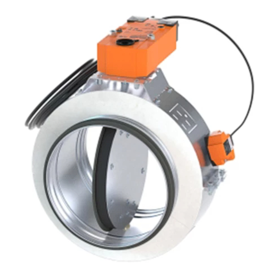
FIRE DAMPER
CIRCULAR SERIES FNC1 - 300 Pa
Cert. N° 1812-CPR-1639
*1MUBFNC1EN* rev 20-12
*1MUBFNC1EN*
www.mp3-italia.it
For further information please refer to the Technical Manual.
As the manufacturer is constantly improving its products, the aesthetic or dimensional features, the technical data, the equipment and acces-
sories indicated could be subject to variations.
This is a 14 page installation booklet.
FNC1
Installation booklet
This is a 14 page installation booklet.
English
FIRE DAMPER
CIRCULAR SERIES FNC1 - 300 Pa
Cert. N° 1812-CPR-1639
*1MUBFNC1EN-LIND* rev 20-12
*1MUBFNC1EN-LIND*
www.lindab.com - Fire dampers are manufactured by MP3 Srl www.mp3-italia.it
For further information please refer to the Technical Manual.
As the manufacturer is constantly improving its products, the aesthetic or dimensional features, the technical data, the equipment and accessories indicated could be subject to variations.
l i n d a b | w e s i m p l i f y c o n s t r u c t i o n
FNC1
Advertisement

Related Manuals for Lindab FNC1


Summary of Contents for Lindab FNC1
- Page 1 *1MUBFNC1EN-LIND* rev 20-12 *1MUBFNC1EN-LIND* www.lindab.com - Fire dampers are manufactured by MP3 Srl www.mp3-italia.it For further information please refer to the Technical Manual. As the manufacturer is constantly improving its products, the aesthetic or dimensional features, the technical data, the equipment and accessories indicated could be subject to variations.
- Page 2 OVER VIEW Fire resistance classification according to EN 13501-3-2009 „ Rigid wall EI 60 S EI 30 S (300 Pa) (300 Pa) EI 60S Installation within vertical rigid wall hole Ø+30 Wall minimum thickness 95 mm Ø Ø Wall minimum resistance class EI 60 min 100 min 100 Mortar or plaster putty or rock wool 35 kg/m³...
- Page 3 Flexible wall EI 60 S EI 30 S (300 Pa) (300 Pa) EI 60 S Installation remote from the vertical light wall hole Ø+30 Wall minimum thickness 95 mm Wall rock wool density up to 35 kg/m³ (optional) Ø Ø Studs made of steel or timber min 100 min 100...
-
Page 4: Electrical Connections
Blade opening mode Make sure that the damper is open before the ventilation system start-up, otherwise there is a risk of product malfunction. To open the damper with the electric motor driven actuator, provi- de power supply to the motor. Refer to the section Electrical con- nections for further information. -
Page 5: Technical Data
Electrical wiring for Belimo BFL24-SR-T modulating motorized version The implementation of a periodic inspection plan allows to guaran- tee the efficiency and functionality of the fire dampers for the fire 24V AC/DC power supply safety of the building. /- Negative (DC) or neutral (AC) black wire Periodic inspection and cleaning „... - Page 6 Installation of flexible connectors in order to balance out the Construction supports characteristics „ „ ventilation ducts expansion The European standard for fire dampers foresees a precise correlation ATTENTION: the following indications must be considered between the wall/floor characteristics and the fire resistance class binding only if legislation or local regulation where the fire obtained, as well as the correlation between wall/floor used for the dampers are installed require the use of flexible connectors.
- Page 7 Concrete floors † Plasterboard thickness 12,5 mm Aerated concrete floors can be built during installation or with pre- Rock wool density up to 35 kg/m³ (optional) formed slabs with interlocking shaped edges according to the fol- Horizontal U-shaped profile Vertical C-shaped profile lowing characteristics: Self-drilling screw Ø...
- Page 8 Screw Ø 3,5 X 35 mm or equivalent Fire damper Ventilation duct Corner support (es. TS11/TS12 Lindab) Fire stopping sealant (reference Soudal Firecryl or equivalent with resistance and reaction to fire equal or higher) between refractory ring and construction support Self-drilling screw Ø3,5 X 25 mm...
- Page 9 Ventilation duct Ventilation duct Rock wool 35 kg/m³, or mortar or plaster putty Corner support (es. TS11/TS12 Lindab) Fire stopping sealant (reference Soudal Firecryl or equivalent with Fire stopping sealant (reference Soudal Firecryl or equivalent with resistance and reaction to fire equal or higher) between refractory ring...
- Page 10 Filling Comply with the minimum distances indicated on section Minimum † distances . Fill the space between the floor and the damper as indicated in the Before and after installation please perform a functional test. Refer to drawing. section Mechanism type for further information . Sealing with concrete is not allowed.
- Page 11 EI 60 S Installation remote from the vertical rigid wall hole Ø+30 Ventilation duct in one piece M8 threaded rod and suspension rings Fire damper Fire stopping sealant (reference Soudal Firecryl or equivalent with resistance and reaction to fire equal or higher) between insulation and sealing Self-drilling screw Ø...
- Page 12 Installation remote from the vertical light wall (plasterboard) „ Refer to the section Construction supports characteristics for further For distance between fire damper and wall less than or equal to 1m, information. only one support is enough as indicated in the drawing. Comply with the minimum distances indicated on section Minimum The support at 20 mm from the fire damper is always mandatory.
- Page 13 EI 60 S Installation remote from the vertical light wall hole Ø+10 Timber studs 45 x 45 mm or metal frame Rock wool density 35 kg/m³ (optional) Plasterboard thickness 12,5 mm type A (EN 520) or higher Ventilation duct in one piece M8 threaded rod and suspension rings Fire damper Fire stopping sealant (reference Soudal Firecryl or equivalent with...
- Page 14 Installations remote from the floor „ Refer to the section Construction supports characteristics for further Damper positioning † information. Connect fire damper to the galvanized steel duct as indicated in the Comply with the minimum distances indicated on section Minimum drawing.
Need help?
Do you have a question about the FNC1 and is the answer not in the manual?
Questions and answers