Advertisement
Quick Links
l i n d a b | we s i m p l i f y c o n s t r u c t i o n
Mounting instruction
Dampers
DRU, DSU, DTU, DTHU, DTH1U, DTH2U, DTBU
DTBCU, DTFU, DTBLU, DSUSN, DSVUSN, DTPU,
PSDRU, TDRU, TDSU
TASU, TATU, TATBU, LKSR
DAU, DA2EU, DAVU, CARU, CAR, MBU, MBFU
FMU, FMDRU, FMDU, DIRU, DIRBU, DIRVU
Advertisement

Related Manuals for Lindab DRU


Summary of Contents for Lindab DRU
- Page 1 | we s i m p l i f y c o n s t r u c t i o n Mounting instruction Dampers DRU, DSU, DTU, DTHU, DTH1U, DTH2U, DTBU DTBCU, DTFU, DTBLU, DSUSN, DSVUSN, DTPU, PSDRU, TDRU, TDSU...
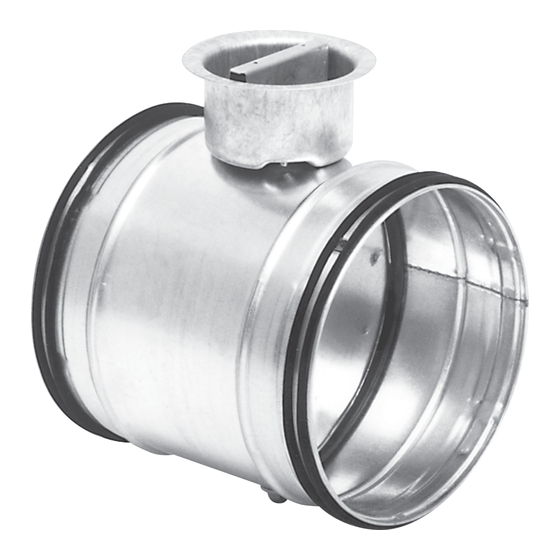
- Page 2 The dampers are then locked by turning them slightly clockwise. Balancing On DRU, PSDRU and TDRU the damper blade is stepless adjustable through 0–90° (0°=fully open, 90°=com- pletely closed) using the knob in the cup. Locking is performed using screws for Pozidrive (PZD2) and the damper angle can be read off a stamped grade on the edge of the cup.
- Page 3 | we s i m p l i f y c o n s t r u c t i o n Dampers DRU, DSU, DTU, DTHU, DTH1U, DTH2U, DTBU, DTBCU, DTFU, DTBLU, DSUSN, DSVUSN, DTPU,...
- Page 4 | we s i m p l i f y c o n s t r u c t i o n Dampers DRU, DSU, DTU, DTHU, DTH1U, DTH2U, DTBU, DTBCU, DTFU, DTBLU, DSUSN, DSVUSN, DTPU,...
- Page 5 | we s i m p l i f y c o n s t r u c t i o n Dampers DRU, DSU, DTU, DTHU, DTH1U, DTH2U, DTBU, DTBCU, DTFU, DTBLU, DSUSN, DSVUSN, DTPU,...
- Page 6 | we s i m p l i f y c o n s t r u c t i o n Dampers DRU, DSU, DTU, DTHU, DTH1U, DTH2U, DTBU, DTBCU, DTFU, DTBLU, DSUSN, DSVUSN, DTPU,...
- Page 7 | we s i m p l i f y c o n s t r u c t i o n Dampers DRU, DSU, DTU, DTHU, DTH1U, DTH2U, DTBU, DTBCU, DTFU, DTBLU, DSUSN, DSVUSN, DTPU,...
- Page 8 l i n d a b | we s i m p l i f y c o n s t r u c t i o n Dampers LKSR Assembly In order to fulfil the requirements for air-tightness class C, the damper must be installed as per ‘Assembly Instruction Rectangular air duct systems’.
- Page 9 Assembly In order to fulfil the requirements for air-tightness class D, the devices must be installed as per ‘Assembly Instruction Lindab Safe’. The devices must be installed with the air flow in the direction of the arrow. The devices allow 50 mm duct insulation without the scale or any motor being hidden.
- Page 10 l i n d a b | we s i m p l i f y c o n s t r u c t i o n Constant/variable flow dampers DAU, DA2EU, DAVU DA2EU Setting of flows The two flows are set by moving the end stops. At delivery the stops are set at largest possible distance.
- Page 11 l i n d a b | we s i m p l i f y c o n s t r u c t i o n Constant/variable flow dampers DAU, DA2EU, DAVU DAVU Setting of flow limits The two flow limits are set by moving the end stops. At delivery the stops are set at largest possible distance.
- Page 12 Assembly CARU In order to fulfil the requirements of tightness class D the damper must be installed as per ‘Assembly Instruction Lindab Safe’. The damper is installed by simply placing it inside a duct. Measurement The dampers normally don’t need any maintenance.
- Page 13 Assembly In order to fulfil the requirements for air-tightness class D, the bends must be installed as per ‘Assembly Instruction Lindab Safe’. The bends allow 50 mm duct insulation without the measuring points being hidden. For 100 mm insula- tion, an insulation cup, IK, is available.
-
Page 14: Flow Meters
Assembly In order to fulfil the requirements for air-tightness class D, the devices must be installed as per ‘Assembly Instruction Lindab Safe’. FMDRU must be installed with the air flow in the direction of the arrow. The devices allow 100 mm duct insulation without sticker or measuring points being hidden. The cup around FMDRU’s damper knob allows 50 mm duct insulation without the knob being hidden. - Page 15 Assembly In order to fulfil the requirements for air-tightness class D, the device must be installed as per ‘Assembly Instruction Lindab Safe’. The device must be installed with the air flow in the direction of the arrow. The device allows 50 mm duct insulation without sticker or measuring points being hidden.
- Page 16 Damper with flow meter DIRU Assembly Mount the dampers according to “Assembly Instructions Lindab Safe” to meet with the requirements for tightness class C. Consider required straight distance after or before disturbance, as mentioned on the card attached to the measurement nozzles, to obtain accurate flow measurement.
- Page 17 l i n d a b | we s i m p l i f y c o n s t r u c t i o n Damper with flow meter DIRU, DIRBU, DIRVU To set the air flow (method 1): To set the air flow (method 2): •...
- Page 18 l i n d a b | we s i m p l i f y c o n s t r u c t i o n Damper with flow meter DIRU, DIRBU, DIRVU Pressure drop graphs with noise Flow graphs for balancing generation for dimensioning The dimensioning graphs show the pressure drop over...
- Page 19 l i n d a b | we s i m p l i f y c o n s t r u c t i o n Damper with flow meter DIRU, DIRBU, DIRVU Pressure drop graphs with noise Flow graphs for balancing generation for dimensioning Ø150...
- Page 20 l i n d a b | we s i m p l i f y c o n s t r u c t i o n Damper with flow meter DIRU, DIRBU, DIRVU Pressure drop graphs with noise Flow graphs for balancing generation for dimensioning Ø250...
- Page 21 l i n d a b | we s i m p l i f y c o n s t r u c t i o n Damper with flow meter DIRU, DIRBU, DIRVU Pressure drop graphs with noise Flow graphs for balancing generation for dimensioning Ø400...
- Page 22 l i n d a b | we s i m p l i f y c o n s t r u c t i o n Damper with flow meter DIRU, DIRBU, DIRVU Measurement accuracy If the velocity profile is asymmetric, the measurement values can differ from the ideal values. For this reason, the flow meter should never be located right up to any flow disturbance.
- Page 23 Mount the damper according to “Assembly Instructions Lindab Safe” to meet the requirements for tight- ness class C.
- Page 24 l i n d a b | we s i m p l i f y c o n s t r u c t i o n Damper with flow meter DIRBU, DIRVU The product normally doesn't requires any maintenance but before maintenance, service or repair make sure that: •...
- Page 25 l i n d a b | we s i m p l i f y c o n s t r u c t i o n Damper with flow meter DIRBU, DIRVU DIRBU Technical data for the motors LM 24 A LM 230 A Power supply ......
Need help?
Do you have a question about the DRU and is the answer not in the manual?
Questions and answers