Advertisement
Quick Links
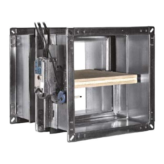
WK45
Installation booklet
English
RECTANGULAR SERIES WK45 - 500 Pa / 300 Pa
Cert. N° 1812-CPR-1006 EN 15650
*1MUBWK45EN* rev 19-05
*1MUBWK45EN-LIND* rev 19-05
*1MUBWK45EN*
*1MUBWK45EN-LIND*
www.mp3-italia.it
www.lindab.com - Fire dampers are manufactured by MP3 Srl www.mp3-italia.it
For further information please refer to the Technical Manual.
As the manufacturer is constantly improving its products, the aesthetic or dimensional features, the technical data, the equipment and acces-
sories indicated could be subject to variations.
This is a 17 page installation booklet.
Advertisement

Related Manuals for Lindab WK45


Summary of Contents for Lindab WK45
- Page 1 WK45 Installation booklet English RECTANGULAR SERIES WK45 - 500 Pa / 300 Pa Cert. N° 1812-CPR-1006 EN 15650 *1MUBWK45EN* rev 19-05 *1MUBWK45EN-LIND* rev 19-05 *1MUBWK45EN* *1MUBWK45EN-LIND* www.mp3-italia.it www.lindab.com - Fire dampers are manufactured by MP3 Srl www.mp3-italia.it For further information please refer to the Technical Manual.
- Page 2 OVER VIEW Fire resistance classification according to EN 13501-3-2009 „ EI 180 S EI 120 S EI 90 S EI 60 S EI 30 S (500 Pa) (500 Pa) (500 Pa) (500 Pa) (500 Pa) EI 120 S Installation within vertical rigid wall Wall minimum thickness 100 mm B X H B X H...
- Page 3 Fire Batt (Weichschott) sealings † EI 120 S EI 90 S EI 60 S EI 30 S (300 Pa) (300 Pa) (300 Pa) (300 Pa) EI 90 S Installation within vertical rigid wall with Fire Batt (Weichschott) sealing Wall minimum thickness 100 mm B X H B X H B X H...
- Page 4 vertical rigid wall EI 120 S B1 + 80 mm Btot + 80 mm H1 + 80 mm Htot + 80 mm light vertical plasterboard wall EI 120 S B1 + 100 mm Btot + 100 mm H1 + 100 mm Htot + 100 mm light vertical plasterboard wall EI 90 S B1 + 75 mm...
-
Page 5: Electrical Connections
Fire dampers pairing „ • It is forbidden to vertically pair two fire dampers with vertical axis. The WK45 patented rectangular fire dampers can be paired side-by- side or vertically (not more than two) using the custom connection ELEC TRICAL CONNEC TIONS Electrical wiring „... - Page 6 "NC" contact of SA microswitch. When the fire blade is open the circuit is open. "NO" contact of SA microswitch. When the fire blade is open the circuit is closed. WK45 - Motorized version † Belimo servomotor: BFL24T, BFN24T, BF24T, BFL230T, BFN230T, BF230T.
-
Page 7: Maintenance And Inspections
Motorized fire dampers electical wiring To connect the dampers to the power supply, proceed as follows: • Check that the voltage and electrical frequency are equivalent to those of the motor of the servomotor (check the motor's informa- tion label); •... -
Page 8: Installation
The implementation of a periodic inspection plan allows to guaran- tee the efficiency and functionality of the fire dampers for the fire safety of the building. Periodic inspection and cleaning „ Periodic inspection shall be performed in accordance with the re- Together with the control activities, it is recommended to visually quirements of the law or by the building regulations or other local verify the absence of corrosion, the integrity of the electrical wiring... - Page 9 Length of end cap with mesh depending on fire damper Flexible connector must be normal flammability and in case of fire the grounding bonding should disconnet to guarantee the com- height H. plete separation between fire damper and connected air duct. When flexible connectors made of conductive material (e.g.
- Page 10 Minimum distances Side vertical wall Distance between fire damper and vertical lateral wall / floor Floor Distance between fire dampers installed within floor Distance between fire dampers installed within vertical wall Distance between fire damper and vertical lateral wall Fire dampers installed within vertical wall Fire dampers installed within floor Installation a [mm]...
- Page 11 Fire Batt (Weichschott) sealings † Fire dampers installed within vertical wall Fire dampers installed within floor Installation a [mm] b [mm] c [mm] d [mm] Paired installation EI 90 S Installation within vertical rigid wall with Fire Batt (Weichschott) sealing Yes.
- Page 12 The following indications are given for the installation walls: Gypsum blocks light walls † • metal profiles minimum width: 49 mm; Gypsum blocks wall can be built with special solid gypsum blocks • metal profiles minimum thickness: 0,6 mm; with interlocking shaped edges as indicated in the supplier's instruc- tions and according to the following characteristics: •...
-
Page 13: Wall Opening
Damper protrusion from Hole size “D1 x D2” Wall minimum thickness “S” Fire resistance classification the wall “E” Sealing [mm] [mm] [mm] EI 120 S Installation within vertical rigid wall EI 120 S From (B+80) x (H+80) Mortar or plaster putty Wall minimum density 500 kg/m³... - Page 14 EI 90 S Installation within vertical light wall (plasterboard) EI 120 S Installation within vertical light wall (plasterboard) D1 Hole base: see table above D1 Hole base: see table above D2 Hole height: see table above D2 Hole height: see table above Damper protrusion from the wall: see table above Damper protrusion from the wall: see table above Plasterboard infill panel, thickness 12,5 mm...
- Page 15 Floor opening Filling † † A opening must be provided in the floor as indicated in the table Fill the space between the floor and the damper as indicated in the and in the drawing table and in the drawing. Damper positioning †...
- Page 16 Damper protrusion from Hole size “D1 x D2” Wall minimum thickness “S” Fire resistance classification the wall “E” Sealing [mm] [mm] [mm] EI 120 S Installation within rigid vertical wall with Fire Batt (Weichschott) sealing Rock wool 140 kg/ Wall minimum density 500 EI 90 S (B+800 max) x (H+800 m³...
- Page 17 D1 Hole base: see table above D2 Hole height: see table above Damper protrusion from the floor: see table above Rock wool panel 50 mm thick with 140 kg/m³ density. PROMASTOP E PASTE or HILTI CFS-S ACR type sealant PROMASTOP E PASTE or HILTI CFS-CT endothermic varnish 17/17...
Need help?
Do you have a question about the WK45 and is the answer not in the manual?
Questions and answers