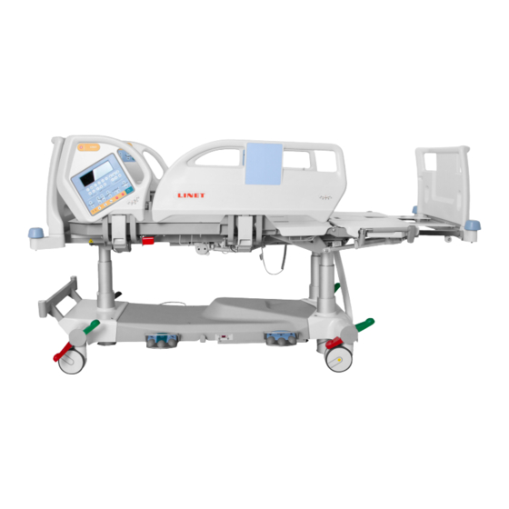
LINET Eleganza 5 Instructions For Use And Technical Description
Positionable bed for intensive care
Hide thumbs
Also See for Eleganza 5:
- User manual and technical description (93 pages) ,
- Service manual (81 pages) ,
- Quick reference manual (9 pages)

Related Manuals for LINET Eleganza 5


Summary of Contents for LINET Eleganza 5
- Page 1 Instructions for Use and Technical Description ELEGANZA 5 Positionable Bed for Intensive Care version with scales and without scales D9U001GE5-0101 Version: 13 Publication Date: 2020-04...
- Page 2 Related links: www.LINET.com D9U001GE5-0101 Version: 13 Publication Date: 2020-04 Copyright © LINET, s.r.o., 2020 Translation © LINET, 2020 All rights reserved. All trademarks and brands are the property of the appropriate owners. The manufacturer reserves the right to changes in the contents of the instructions for use that relate to the product´s technical regulations.
-
Page 3: Table Of Contents
11.5.9 Bed Extension ............58 1.6 Serial Labels with UDI ..........9 11.5.10 CPR Position ............59 1.6.1 Serial Label for Eleganza 5 with scales ....9 11.5.11 Cardiac Chair Position ..........60 1.6.2 Serial Label for Eleganza 5 without scales ....9 11.5.12 Lateral Tilt .............61 1.7 Acoustic signalisation ..........11... - Page 4 17.1.1 Daily Cleaning ............93 17.1.2 Cleaning before Changing Patients ....... 93 17.1.3 Complete Cleaning and Disinfection ...... 93 18 Troubleshooting ............94 19 Maintenance ...............95 19.1 Regular maintenance ..........95 19.2 Spare Parts ...............95 19.3 Safety Technical Checks ...........95 20 Disposal ..............96 20.1 Environment Protection ..........96 20.2 Disposal ..............96 20.2.1 Within Europe ............96...
-
Page 5: Symbols And Labels On The Bed
KEEP DRY (PROTECT FROM HUMIDITY) PAPER RECYCLING SYMBOL DO NOT STACK DURING STORAGE DO NOT USE HAND TRUCK HERE OVERSEAS PACKAGE: STACKING LIMIT BY NUMBER (3 PACKAGES FOR TRANS- PORT) OVERSEAS PACKAGE: STACKING LIMIT BY NUMBER (5 PACKAGES FOR STORAGE) 1.5 Symbols and Labels on the Bed READ INSTRUCTIONS FOR USE GO BUTTON (PRESS TO ACTIVATE CONTROL ELEMENT) - Page 6 SAFE WORKING LOAD PHYSICAL DESCRIPTION OF AN ADULT (DESIGNATION OF MEDICAL BED FOR ADULTS) USE MATTRESS RECOMMENDED BY MANUFACTURER DO NOT PUT ANY OBJECTS ON UNDERCARRIAGE CALFREST LOAD LIMIT WARNING AGAINST CRUSHING OR TRAPPING OF HANDS JACK FOR ATTACHMENT OF CONDUCTOR FOR POTENTIAL EQUALISATION CPR LEVER GENERAL WARNING SIGN CAUTION...
- Page 7 FOR INDOOR USE ONLY MAXIMUM PATIENT WEIGHT WEIGHT OF BED CE MARK FOR Eleganza 5 WITH SCALES CE MARK FOR Eleganza 5 WITHOUT SCALES AND FOR OptiCare WEEE SYMBOL (RECYCLE AS ELECTRONIC WASTE, DO NOT PUT INTO THE HOUSEHOLD WASTE) RECYCLING SYMBOL...
- Page 8 THIS COMPONENT CONTAINS LITHIUM - DO NOT PUT INTO THE HOUSEHOLD WAS- (If Eleganza 5 is equipped with Integration Module (SafetyMonitor System), it contains lithium battery.) MEDICAL DEVICE (compatible with Medical Device Regulation) D9U001GE5-0101_13...
-
Page 9: Serial Labels With Udi
Pictures of serial labels below serve just for explanation of the signs and fields on the serial labels. 1.6.1 Serial Label for Eleganza 5 with scales Fig. Serial Label with UDI (Eleganza 5 with scales) 1.6.2 Serial Label for Eleganza 5 without scales Fig. - Page 10 Fig. Accessory Label Address of Manufacturer Manufacturing Date (Year-Month-Day) DI (Device Identifier) / GTIN (Global Trade Item Number) 1D Bar code GS1-128 (Serial Number) Serial Number PI (Product Identifier) 2D Bar Code (GS1 DataMatrix) DI+PI=UDI Scales Abbreviations maximum capacity of the weighing instrument minimum capacity of the weighing instrument...
-
Page 11: Acoustic Signalisation
1.7 Acoustic signalisation SOUND MEANING CONTINUOUS SOUND overheating accumulator overcurrent scales overload (only version with scales) actuator overload BEEP + CONTINUOUS SOUND Siderail Signal (lateral tilt + head siderail or foot siderail down) REPEATED BEEP: 0,6s sound / 2,6s silence STOP error (all STOP buttons are disabled) MELODY: 3 beeps, pause, 2 beeps, longer pause, 3 beeps, Bed Exit Alarm (only version with scales) -
Page 12: Mains Power Led (Iboard Standard, Attendant Control Panel)
1.8.2 Mains Power LED (iBoard Standard, Attendant Control Panel) MAINS POWER LED MEANING connected to the mains flashing: 0,6s lit / 0,6s not lit keyboard error (flashing inverted to Lock LED) error (first fault) flashing: 0,1s lit / 0,1s not lit service mode not lit disconnected from the mains power transformer switching error 1.8.3 Accumulator indicator (iBoard Standard, Attendant Control Panel) ACCUMULATOR INDICATOR MEANING... -
Page 13: Definitions
1.9 Definitions Basic Bed Configuration The pricelist model configuration, not including a mattress. Bed Weight The value depends on the product configuration, accessories or customer adjustments. Clearance of Undercarriage The height from the floor to the lowest point of the undercarriage between the castors, for the manipulation of accessories under a braked bed in the standard position. -
Page 14: Safety Instructions
WARNING! Inappropriate handling of the power supply cord, e. g. by kinking, shearing or other mechanical damages is hazardous! WARNING! When routing cables from other equipment in the Eleganza 5 bed avoid squeezing those between parts of the Eleganza 5 bed! WARNING! Eleganza 5 bed should not be used with bed hoists and bed lifts! WARNING! The bed is intended for adults. - Page 15 WARNING! During specific investigations or treatments the significant risks of reciprocal interference posed by ME equi- pment may occur. WARNING! Staff expert assessment is needed to consider all individual cases of contraindications! WARNING! Certain bed positions are not suitable for specific diagnosis/medical conditions. Fowler position is not suita- ble for spinal cord injuries! Trendelenburg position is not suitable for patients with higher intracranial pressu- WARNING! Length adjustment of the bed must be proportional to the height of patient! Risk of trapping or squeezing because of patient´s body constitution disproportionate to the size of mattress support platform! WARNING! Any serious incident that has occurred in relation to the device should be reported to the manufacturer and the...
- Page 16 ► Follow the instructions carefully. ► Use the bed exclusively if it is in perfect working order. ► If necessary, check the bed functions daily or at each shift change. ► Ensure any user has read and understood the instructions for use completely before operating the product. ►...
-
Page 17: Intended Use
3 Intended use The intended use is the hospitalization of the patient in the intensive and acute care units, which includes above all the following aspects: ► Adjustment of the specific positions needed for the preventive reasons, routine nursing, treatments, mobilization, physio- therapy, examinations, sleeping, and relaxation. -
Page 18: Product Description
15. Foot Board Safety Lock Corner bumper 5 Technical Specification All technical data are rated data and are subject to construction and manufacturing tolerances. WARNING! If Eleganza 5 bed is used with OptiCare integrated mattress system respect values of mechanical and electri- cal specifications which can harm none of them! D9U001GE5-0101_13... -
Page 19: Identification Of Applied Parts (Type B)
250 Kg SWL (Lifting Pole Safe Working Load) 75 Kg Maximum Patient Weight 185 Kg Application Environment in accordance with IEC 60601-2-52 1, 2 5.4 Environment conditions (Eleganza 5) Use Conditions Ambient Temperature 10°C - 40°C Relative Humidity 30% - 75 % Atmospheric Pressure 795 hPa - 1060 hPa... -
Page 20: Electrical Specifications (Eleganza 5)
Version 100 V 2 x T4.0A L 250 V NOTE Upon request, LINET ® can deliver hospital beds with electrical specifications that comply with regional standards (custom voltage, different mains plugs). 5.6 Electromagnetic Compatibility Bed is intended for hospitals except for near active HF surgical equipment and the RF shielded room of a medical system for magnetic resonance imaging, where the intensity of EM disturbances is high. -
Page 21: Manufacturer Instructions - Electromagnetic Emissions
5.6.1 Manufacturer instructions - electromagnetic emissions Emission Test Compliance RF emissions Group 1 CISPR 11 RF emissions Class B CISPR 11 Harmonic emissions Class A IEC 61000-3-2 Voltage fluctuations / flicker emissions Complies IEC 61000-3-3 5.6.2 Manufacturer instructions - electromagnetic susceptibility Immunity Tests Compliance level Electrostatic discharge (ESD) -
Page 22: Use And Storage Conditions
► Use exclusively Hospital Grade or Hospital Only receptacles for grounding. Eleganza 5 and OptiCare are designed for use in rooms for medical purposes. Electrical installations must therefore meet local norms laying down the necessary conditions for electrical installations. ►... -
Page 23: Scope Of Delivery And Bed Variants
Notify the carrier and supplier of any deficiencies or damages immediately as well as in writing or make a note on the delivery note. 7.2 Scope of Delivery ■ Eleganza 5 medical bed ■ Instructions for use 7.3 Eleganza 5 Variants... -
Page 24: Putting Into Service
Ensure that putting into service is performed exclusively by manufacturer´s customer service or trained hospital personnel. NOTE For safe, easy handling, LINET ® recommends having two technicians assemble the bed. Set up the bed as follows: ► Unpack the bed. -
Page 25: Head Board And Foot Board
Removing the Isolating Foil To remove isolating foil: ► Remove isolating foil from mains control box by pulling strap. ► Check if isolating foil is complete and undamaged as shown in figure Detail of Isolating Foil. ► If isolating foil is damaged, contact the manufacturer’s service department immediately. -
Page 26: Mattress Support Platform
8.3 Mattress Support Platform Eleganza 5 bed has 4-part Mattress support platform consisting of Backrest, Seat section, Thighrest and Calfrest. The Mattress support platform without x-ray cassette holder has 4 removable covers of Mattress support platform (1, 2, 3 and 4). -
Page 27: Before Use
8.5 Before Use Prepare the bed for use as follows: ► Connect the bed to the mains. ► Charge the accumulator. ► Raise and tilt the mattress support platform to the highest position. ► Lower and tilt the mattress support platform to the lowest position. ►... -
Page 28: Accumulator
10 Accumulator WARNING! When the bed is not connected to the mains and accumulator is not sufficiently charged all electrical func- tions of the bed are blocked! Purpose The accumulator serves as a backup during power failures or for emergency bed positioning. ► Use only accumulator approved by the manufacturer. ► Check the functionality of the accumulator at least once a month and have the accumulator changed if necessary. The manufacturer will assume no responsibility for any damage to the bed or the accumulator caused by: ■... -
Page 29: Replacing The Accumulator
Signalisation The LED (on iBoard Standard or Attendant Control Panel) indicates the accumulator charge status: Yellow LED Accumulator charge status Not lit Accumulator is charged. Short flashing (shortly lit, longer not lit) (circa 1.8s) Accumulator is charging - continue charging until the LED is extinguished. -
Page 30: Removing The Bed From Use
Discharged accumulator The accumulator is regarded as discharged if the following condition is met: ► Defined decrease of voltage depending on discharging current ► This status is indicated by the accumulator status indicator flashing quickly. ► The electric CPR position is the only possible position. ►... -
Page 31: Manipulation
11 Manipulation WARNING! Risk of injury when adjusting the bed! ► Ensure that there are no body parts between the mattress support platform elements and the mattress support platform frame when adjusting the bed. ► Ensure that there are no body parts below the mattress support platform frame before adjusting the bed. 11.1 Siderails The split siderails are components of the bed in contact with patient. - Page 32 SIDERAIL DESCRIPTION (version with iBoard Basic) 1. iBoard Basic 2. Siderail Handle Fig. Siderails (version with iBoard Basic) 3. Correct Placement of Handset 4. Siderail Release Handle 5. Angle Indicator MANIPULATION To raise siderails up: ► Grab siderail by Siderail Handle (2). ►...
-
Page 33: Castor Control
SIDERAIL DESCRIPTION (version without scales) 1. Siderail Handle 2. Correct Placement of Handset Fig. Siderails (version without scales) 3. Siderail Release Handle 4. Angle Indicator MANIPULATION To raise siderails up: ► Grab siderail by Siderail Handle (1). ► Pull siderail up until it latches. You will hear audible „click“. To release siderails down: ►... -
Page 34: Cpr Backrest Release
Castor control lever positions: 1. Forward Movement - Steering (GREEN PEDAL DOWN) An arrested front castor determines the direction of movement. If the bed is equipped with a fifth castor, this castor determines the direction of movement. 2. Unrestricted Movement All four castors are unlocked. -
Page 35: Iboard Standard
POSITIONING iBoard Attendant Handset Patient Control Panels Bed Height Lateral Tilt Standard Control (head siderail, foot Foot Control Foot Control Panel siderail) Backrest Thighrest Calfrest Bed Height Autocontour Examination Position Emergency Trendelenburg Position Antitrendelenburg and Trendelenburg Tilt Bed Extension CPR Position Cardiac Chair Position Mobilization Position Lateral Tilt... - Page 36 1. Display 2. Keyboard - Scales Section 3. Keyboard - Bed Exit Monitoring/ SafetyMonitor Section 4. Keyboard - Positioning Section 5. Keyboard - Settings Section or Setting Section and Mattress Section Fig. iBoard Standard with Mattress Keyboard Settings Section 1 2 3 4 Fig.
- Page 37 Available options are: YEAR / MONTH / DAY / HOUR / MINUTE / WEIGHT TIMER. It is not possible to set value for option WEIGHT TIMER in the version of Eleganza 5 bed without scales. NOTE: Options are displayed in this order. YEAR follows after WEIGHT TIMER again.
- Page 38 ► To set the value use buttons ► Press button to save the value and continue to the setting of the other option. The value is saved by exiting. Icon 5 indicates another option automatically and icon 8 indicates its actual value. To set day: ►...
- Page 39 Positioning Section 22 21 20 15 16 Fig. Positioning Section - Display and Keyboard 1. Autocontour Adjustment Buttons (simultaneous movement of the Backrest and Thighrest) 2. Accumulator charge status LED 3. Mains Power LED 4. Antitrendelenburg Tilt Button 5. Locked Backrest LED 6. Backrest Adjustment Buttons 7. Trendelenburg Tilt Button 8. Thighrest Adjustment Buttons 9. Mobilization Position Button 10. Locked Thighrest, Calfrest and Bed Extension LED ...
- Page 40 Scales Section (only version with scales) Eleganza 5 is optionally equipped with a weighing system that allows weighing the patient in bed. There are control buttons and display for the weighing system on the Scales section of iBoard Standard. Scales functions are described in chapter Scales Cont- rol.
- Page 41 Statuses (iBoard Standard) Status Meaning Required Action LOCK Function locked. Unlock function if required! Incorrectly inserted X-Ray Cassette Insert X-Ray Cassette Holder X-RAY Holder. correctly! GO Button not activated. Press GO Button! Lateral Tilt disabled when siderail folded Raise siderail up to enable additi- SIDERAIL down.
- Page 42 FAULT Contact service department Column Unit Error. COLUMN + approved by manufacturer. Remove an object from Movement of the Mattress support plat- SAFE STOP + undercarriage to continue in form stopped by function Safestop. adjusting the bed height. Close manual CPR to enable CLOSE MANUAL CPR The mattress inflating failed.
-
Page 43: Iboard Basic (Optional)
11.4.2 iBoard Basic (optional) The iBoard Basic is the optional Control Element for the caregivers. It is integrated in the outside of both head siderails. Only versi- on with scales can be equipped with iBoard Basic. The iBoard Basic serves for control of scales and control of Bed Exit Monitoring. ►... - Page 44 X-RAY Incorrectly inserted X-Ray Cassette Insert X-Ray Cassette Holder correctly! Holder. Safe Working Load exceeded Remove load! OVERLOAD (more than 10 kg over Safe Wor- king Load). Lateral Tilt disabled (Load more Remove load to enable Lateral Tilting again! than 200 kg). STOP System Fatal Error.
-
Page 45: Attendant Control Panel
11.4.3 Attendant Control Panel The Attendant Control Panel is a standard Control Element. The Attendant Control Panel can be hung on the foot board or on side- rails if required. It is possible to hold the Attendant Control Panel in the hand while operating. ►... -
Page 46: Handset (Optional)
Activating GO Button The button activates the keyboard of all control elements for 3 minutes. The function of the GO button is identical on all control elements. During this time the following is possible: ► Adjusting individual mattress support platform elements by pressing the corresponding function buttons. ►... -
Page 47: Patient Control Panels
1 2 3 1. Thighrest Adjustment Button 2. Thighrest/Backrest Lock LED 3. Backrest Adjustment Button ... -
Page 48: Bed Height Foot Control (Optional)
11.4.6 Bed Height Foot Control (optional) The foot control is optional and allows setting the Height of the bed with one’s feet. Press the selected pedal twice in 3 seconds. Bed Height Foot Control is activated for 20s after this procedure. 1. -
Page 49: Bed Positioning
11.5 Bed Positioning 11.5.1 Backrest To position Backrest use: ► iBoard Standard ► Attendant Control Panel ► Handset ► Patient Control Panel (in foot siderail) ► Patient Control Panel (in head siderail) Fig. Backrest Angle on iBoard Standard Display iBoard Standard Display shows Backrest Angle. During continuous positioning Backrest stops automatically in 30 and 45 degrees (the beep will appear). To continue in ... -
Page 50: Thighrest
Attendant Control Panel: 1. Backrest Up ► Press button 2. Backrest Down ► Press selected part of Backrest Adjustment Button until intended position is reached. Handset: Fig. Backrest Adjustment Button (Attendant Control Panel) ► Press button ► Press selected part of Backrest Adjustment Button until intended position is reached. - Page 51 iBoard Standard: ► Press button ► Press selected part of Thighrest Adjustment Button until intended position is reached. Patient Control Panel (in foot siderail): ► Press button ► Press selected part of Thighrest Adjustment Button Fig. Thighrest Adjustment until intended position is reached. Button (iBoard Standard, Pati- ent Control Panels) Patient Control Panel (in head siderail):...
-
Page 52: Calfrest
11.5.3 Calfrest To position Calfrest position Thighrest fi rstly. To position Calfrest use: ► iBoard Standard ► Attendant Control Panel iBoard Standard: ► Press button ► Press selected part of Calfrest Adjustment Button until intended position is reached. Fig. Calfrest Adjustment Button (iBoard Standard) 1. -
Page 53: Bed Height
11.5.4 Bed Height To position Bed Height use: ► iBoard Standard ► Attendant Control Panel ► Hanset ► Bed Height Foot Control NOTE It is possible to use Button on Mobi-Lift (optional) to position Bed Height. iBoard Standard: ► Press button ►... -
Page 54: Autocontour
Handset: 1. Mattress support ► Press button platform Up ► Press selected part of Bed Height Adjustment Button 2. Matress Platform until intended position is reached. Down Fig. Bed Height Adjustment Button (Handset) Bed Height Foot Control: ► Press the selected Bed Height Pedal and release it. ►... -
Page 55: Emergency Trendelenburg Position
To position Autocontour use: ► iBoard Standard ► Handset ► Patient Control Panel (in foot siderail) ► Patient Control Panel (in head siderail) iBoard Standard: ► Press button ► Press selected part of Autocontour Adjustment Button until intended position is reached. Patient Control Panel (in foot siderail): ►... -
Page 56: Antitrendelenburg And Trendelenburg Tilt
Trendelenburg position provides anti-shock conditions for the patient. During Trendelenburg Position Mattress support platform is straightened in the tilt. To position Emergency Trendelenburg Position use: ► Attendant Control Panel Attendant Control Panel: ► Press button ► Press Trendelenburg Position Button until intended position is reached. Fig. Trendelenburg Position Button (Attendant Control Panel) 11.5.7 Antitrendelenburg and Trendelenburg Tilt Fig. -
Page 57: Examination Position
iBoard Standard: ► Press button ► Press Trendelenburg Tilt Button until intended position is reached. Fig. Trendelenburg Tilt Button (iBoard Standard) iBoard Standard: ► Press button ► Press Antitrendelenburg Tilt Button until intended position is reached. Fig. Antitrendelenburg Tilt Button (iBoard Standard) Attendant Control Panel: 1. -
Page 58: Bed Extension
To position Examination Position use: ► Bed Height Foot Control Bed Height Foot Control: ► Press Examination Position Pedal and release it. ► Press and hold Examination Position Pedal once more until intended position is reached. NOTE: Bed Height Foot Control is activated for 30s after this procedu- Fig. -
Page 59: Cpr Position
11.5.10 CPR Position In CPR Position bed reaches fl at Mattress support platform. If the bed is equipped with Opticare mattress, pressing CPR Button will also defl ate the mattress. To position CPR Position use: ► iBoard Standard ► Attendant Control Panel iBoard Standard: ► Press CPR Position Button until intended position is reached. Attendant Control Panel: Fig. CPR Button (iBoard ►... -
Page 60: Cardiac Chair Position
11.5.11 Cardiac Chair Position To position Cardiac Chair Position use: ► iBoard Standard ► Attendant Control Panel iBoard Standard: ► Press button ► Press Cardiac Chair Position Button until intended position is reached. Fig. Cardiac Chair Position Button (iBoard Standard) Attendant Control Panel: ►... -
Page 61: Lateral Tilt
11.5.12 Lateral Tilt It is not possible to position Lateral Tilt with a siderail folded down without use of an additi- onal function. To position Lateral Tilt use: ► iBoard Standard ► Lateral Tilt Foot Control ► Attendant Control Panel iBoard Standard Display shows Lateral Tilt Angle. -
Page 62: Mobilisation Position
11.5.13 Mobilisation Position In Mobilisation Position bed is descending to the lowest Bed Height and Backrest reaches the maximum angle. To position Mobilisation Position use: ► iBoard Standard iBoard Standard: ► Press button ► Press Mobilisation Position Button until intended position is reached. Fig. Mobilisation Position Button 11.5.14 Ergoframe ® Ergoframe is the kinematic system of Backrest and Thighrest Adjustment resulting in extension of the Mattress support platform in the seat section. -
Page 63: Scales Control (Only Version With Scales)
12 Scales Control (only version with scales) Use iBoard Standard or iBoard Basic to control the scales. iBoard Standard 1. ZERO/T Button (tare or zero Fig. Scales Section (iBoard Standard) - Display and Keyboard scales) 2. WEIGHT/CLEAR Button (cancel) 3. HOLD Button iBoard Basic 4. -
Page 64: Taring
CAUTION! Incorrect use of scales due to incomplete preparation! ► Before each patient admission tare the scales. 12.2 Taring Taring can be done in a range of 5kg to 249.5kg. Taring is used to set “0” on the display before placing the patient on the bed. Taring must be done with an unloaded bed with mattress, bed sheets, pillows and necessary accessories, without the patient. -
Page 65: Bed Overload
NOTE To save another weight value repeat this procedure. During one day repeated savings mean rewriting the same record. During rewriting Status Indicator (6) shows SAVE. To cancel saving patient´s weight: ► Press button during saving. NOTE Maximum number of saved values is 9. Icon shows records from M1 to M9. -
Page 66: Zeroing Scales
12.9 Zeroing Scales Zeroing is only possible in a range of ±5kg from factory zero. Zeroing is used to reset weight on the display and set up user zero, which sets the maximum weight range of the weighing system. Zeroing must be done with an empty, unloaded bed, without the mattress and accessories. -
Page 67: Preparation
iBoard Basic 1. ON Button 2. Inner Zone Button 3. Outer Zone Button 4. VOLUME Button (3 levels) 5. PAUSE Button 6. OFF Button 7. PAUSE Coundown Icon (with remaining minutes) 8. Volume Icon (3 levels) 9. Bed Exit Monitoring Activated (Outer Zone) 10. -
Page 68: Alarm
13.4 ALARM Alarm is triggered when patient has left selected monitored zone or PAUSE period elapsed and patient is not in ordered position. To stop Alarm: ► Press button Bed Exit Monitoring is deactivated and icon appears on the display. The audible alarm is muted. -
Page 69: Deactivation Of Bed Exit Monitoring
13.7 Deactivation of Bed Exit Monitoring To deactivate Bed Exit Monitoring: ► Press button Icon appears on the display. 14 Equipment Fig. Bed Exit OFF (iBoard Basic) 14.1 Accessory Rail with plastic hooks (optional) Accessory Rail with 2 plastic hooks is intended for hanging accessories. It is located on the sides of bed. -
Page 70: I-Drive Power (Optional)
14.5 i-Drive Power (optional) i-Drive Power System - Basic Description It is possible to equip the bed with the i-Drive Power wheel. The i-Drive Power helps hospital staff to drive the bed during patient transport with minimal manpower. The i-Drive wheel is located in the center of the bed under the undercarriage. i-Drive Power is equipped with its own accumulator and charger and it is not dependent on the bed functions so, if discharged you can still use the bed functions. - Page 71 Each bed can transport only single patient at a time and cannot be used to transport other items (except bed accessories in secured position). NOTE For information concerning uses other than those outlined in the “Specifications of Use” section above, please contact LINET ®. Manipulation CAUTION! Damage to i-Drive Power main...
-
Page 72: I-Drive Power Activation/Deactivation
NOTE Raising and lowering of the i-Drive wheel is electrically controlled by the i-Drive activation panel. 14.5.1 i-Drive Power Activation/Deactivation To activate the i-Drive Power: Check, if the mains switch of i-Drive Power is activated. Press the Activation button located on the Activation Panel. The i-Drive wheel will lower and the green indicator will flash. -
Page 73: Braking
Check, if the mains switch of i-Drive Power is activated. Press the button on the Activation Panel. The i-Drive wheel will lower and the LED will flash. Place your hand on the Safety Sense touch sensor (1) and push the button or button or button Your hand must be placed on the Safety Sense sensor to use the i-Drive Power, if released, the i-Drive Power will stop. - Page 74 Fault Signalization The system is protected against failure states, by stopping and braking the drive system, and respective signalization. The fault indicator flashing briefly and the accumulator indicator shows the fault state. Some defects are cleared automatically (e.g.: drive overheating). When drive or electronics is overheated, an short acoustic signal occurs before the drive is blocked. Error LED1 LED2...
-
Page 75: Mobi-Lift ® (Optional)
i-Drive Power Maintenance Periodical maintenance of the i-Drive Power must be done by qualified service technician or authorized service organization at least once a year. To continue maintenance please see chapter Maintenance. Service technician must check the following: ► accumulator status and eventual replacement of the accumulator (after maximum of three years of duty) ►... -
Page 76: Nurse Call
Necessary Steps before the Exami- nation ► Make sure that patient is in centre of bed. ► Make sure that backrest is in lowest position and siderails are raised up. ► Pull out x-ray cassette holder. ► Insert x-ray cassette (format 43×35 cm (16.93 in. -
Page 77: Usb Connector
Fig. Nurse Call Control Element (outer side of head siderail) 1. Nurse Call Button 2. Speaker and Microphone Fig. Nurse Call Control Element (inner side of head siderail) - version 1 14.10 USB Connector WARNING! Risk of injury due to incorrect use! ► Ensure accessory pluged in USB connector is in pristine condition! User of the bed is responsible for the fact that this requirement is met. - Page 78 ► Pull both Pushing Handles out of the fixed bushings on the head end crossbar. Insertion of the Pushing Handles to their fixed bushings: ► Insert both Pushing Handles to their fixed bushings on the head end crossbar. Fig. Pushing Handles on the Eleganza 5 bed D9U001GE5-0101_13...
-
Page 79: Mattress
CAUTION! Incompatibility with bed due to incorrect mattress dimensions! ► Check maximum approved mattress dimensions (chapter Technical Specification). The manufacturer recommends the use of the following mattress systems on the Eleganza 5 bed: PASSIVE MATTRESSES ACTIVE MATTRESSES ■ CliniCare 10 ■ ... -
Page 80: Active Mattress (Not Integrated)
Fig. Fixation of the passive mattress with straps on the mattress support platform of Eleganza 5 bed 15.2 Active Mattress (not integrated) WARNING! Follow instructions for use of a compatible active mattress carefully! CAUTION! Risk of material damage due to an incorrect fixation of compatible active mattress on the mattress support platform! ► Adjust the bed to maximum Cardiac Chair Position before fixing all the straps of the inflated mattress to the... -
Page 81: Opticare (Integrated Mattress)
CAUTION! Material damage due to incorrect installation of SCU! ► If the SCU does not come factory-fi tted, have it installed by a service engineer authorised by LINET ®. 15.3.1 Mattress Screen 5 6 7 Fig. Mattress Display and Keyboard (iBoard Standard) -
Page 82: Accessories
16 Accessories 1. Lifting pole 2. Infusion stand WARNING! 3. Oxygen bottle holder Risk of injury due to incompatible accessories! 4. Ventilation circuit holder ► Use exclusively original accessories from the manufacturer. The manufacturer is not responsible for the use of unapproved accessories. WARNING! Risk of injury due to damaged accessories! ► Use exclusively accessories in perfect condition. Accessory head end foot end sides... -
Page 83: Lifting Pole
Attach a plastic grab handle with an adjustable strap to the lifting pole. NOTE The date of manufacture is marked on the grab handle. LINET® recommends replacing the plastic grab handle every four years. Fig. Places for lifting pole (sleeve fittings on accessory adapter) Fig. -
Page 84: Oxygen Bottle Holder
Fig. Places for infusion stand (sleeve fittings on accessory adapter) Fig. Infusion stand 16.3 Oxygen Bottle Holder WARNING! Risk of injury with oxygen bottle holder due to incorrect use or due to careless driving! ► Ensure the oxygen bottle holder is correctly fitted in correct position. ► It is necessary to place oxygen bottle holder (with or without O2 bottle) before transport to secure transport position. -
Page 85: Ventilation Circuit Holder
16.4 Ventilation Circuit Holder The ventilation circuit holder prevents extubation of the patient connected to the ventilator. ► Always use LINET ® ventilation circuit holder to prevent extubation during any procedures. Applying ventilation circuit holder: ► Put ventilation circuit holder in hole on right or left side of the Backrest frame. -
Page 86: Writing Shelf
Make sure the fall risk assessment was done properly before Protector use. The Protector is an optional accessory for the Eleganza 5 bed. The main purpose of the Protector is to reduce the risk of fall especially at very risky patients (confused restless patients). The Protector can be used with extended or standard beds. - Page 87 Fig. Placement of Protector Placement Attach the Protector to the bed as follows: ► Insert the Protector pin into the casing in the protective ring at the corner of the foot end of the bed. ► Ensure that the fixing element is secured to the telescopic profile of the bed extension.
-
Page 88: Urinary Bag Holder
Traction Frame is inserted to the holes in the Accessory Adaptor at head end and to the holes in the Traction Frame Holder at foot end. Fig. Safe Working Load of the hooks (Infusion Holder) Fig. Safe Working Load of the pulley Fig. Eleganza 5 with Traction Frame (side view) D9U001GE5-0101_13... -
Page 89: Safetymonitor
SafetyMonitor system consists of installed server, secure intranet infrastructure (Wi-Fi or LAN), screen in the nurse station (PC or tablet or smartphone), Tag on the wall, parked Eleganza 5 EMR ready bed with iBoard Standard or iBoard basic, Integration Modu- le, Localisation Receiver, LAN connector and LAN cable. - Page 90 iBoard Standard (SafetyMonitor Section) 15 14 Fig. SafetyMonitor Section (iBoard Standard) - Display and Keyboard 10. Volume indicator (3 levels of sound pressure) 1. ON button (RUN) 11. Bed Exit Monitoring Activated (Outer Zone Monitoring) 2. Inner Zone button (Bed Exit Monitoring) 12.
- Page 91 iBoard Basic (SafetyMonitor Section) Fig. SafetyMonitor Section (iBoard Basic) - Display and Keyboard 1. ON button (RUN) 2. Inner Zone button (Bed Exit Monitoring) 3. Outer Zone button (Bed Exit Monitoring) 4. OFF button 5. Volume button (3 levels of sound pressure) 6.
-
Page 92: Cleaning/Disinfection
17 Cleaning/Disinfection WARNING! Risk of injury due to accidental bed movement! ► Always disable the function buttons when cleaning between the undercarriage and mattress support platform. CAUTION! Material damage due to incorrect cleaning/disinfection! ► Do not use washing machines. ► Do not use pressure or steam cleaners. ►... -
Page 93: Cleaning (Eleganza 5)
17.1 Cleaning (Eleganza 5) Prepare for cleaning as follows: ► Put the mattress support platform in the highest position. ► Adjust the back and thigh rests so that the reverse sides are accessible. ► Disable the function buttons on the control elements using the Attendant Control Panel. -
Page 94: Troubleshooting
■ Brakes ■ Interior parts (accessible after removing mattress support platform covers) 18 Troubleshooting DANGER! Risk of mortal injury due to electric shock! ► If a fault occurs, have the electric motor, power box or other electrical parts repaired by qualified personnel exclusively. ► Do not open the protective covers of the electric motor or the power box. Error/Fault Cause Solution... -
Page 95: Maintenance
Ensure that maintenance is performed exclusively by manufacturer´s customer service or by authorised service personnel certified by the manufacturer. ► If the defect cannot be repaired, do not use the bed. LINET ® recommends attaching the maintenance plaque to the bed. 19.1 Regular maintenance ► Check regularly movable parts for wear. -
Page 96: Disposal
Based on the Directive No. 2002/96/ EC (Directive WEEE - Waste, Electric and Electronic Equipments) the company LINET, s. r. o. is registered in the List of Electric and Electronic Equipment Producers (Seznam výrobců elektrozařízení) on the Ministry of the Environment of the Czech Republic... -
Page 97: Warranty
21 Warranty LINET ® will only be held responsible for the safety and reliability of products that are regularly serviced, maintained and used in accordance with the safety guidelines. Should a serious defect arise that cannot be repaired during maintenance: ►...
Need help?
Do you have a question about the Eleganza 5 and is the answer not in the manual?
Questions and answers