
Related Manuals for nvent Raychem TCON-CSD/20


Summary of Contents for nvent Raychem TCON-CSD/20
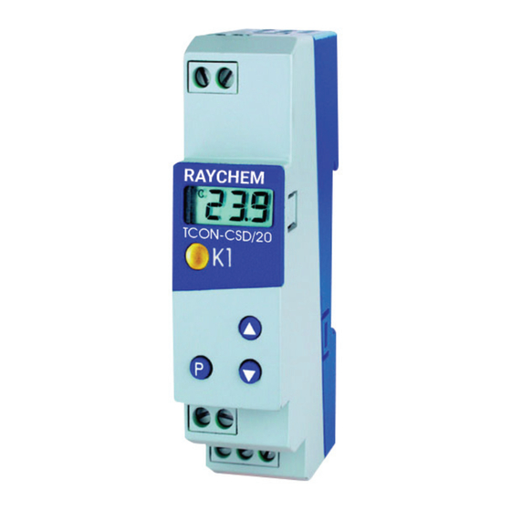
- Page 1 TCON-CSD/20 DIGITAL THERMOSTAT-DIGITALER THERMOSTAT-THERMOSTAT NUMÉRIQUE Operating Instructions Betriebsanleitung Notice de mise en service...
- Page 3 TCON-CSD/20 DIGITAL THERMOSTAT Operating Instructions...
- Page 4 OVERVIEW OF OPERATION nVent.com | 4...
-
Page 5: Table Of Contents
4.1 Displays and controls ..............................10 4.2 Setting the instrument functions (parameter level) ....................11 4.3 Allocating user rights (enabling level) .......................... 18 5 Operation ��������������������������������������������������������������������������������������������������������������������������������������������������������������19 6 Technical data ������������������������������������������������������������������������������������������������������������������������������������������������������20 6.1 Setup program ................................23 7 Alarm messages ���������������������������������������������������������������������������������������������������������������������������������������������������24 nVent.com | 5... -
Page 6: Identifying The Instrument
Please contact the nearest subsidiary or the head office in such a case. Please read these operating instructions before commissioning the instrument. Keep the manual in a place that is accessible to all users at all times. Please assist us to improve these operating instructions, where necessary. nVent.com | 6... -
Page 7: Assembling
2� ASSEMBLING Disassembling °C ≤ 75 nVent.com | 7... -
Page 8: Electrical Connection
(via a separate mains supply switch, for instance). • Supply Measurement input and supply 230V AC and 115V AC Short-circuit-proof Electrically isolated from each other 12 — 24V DC and 24V AC Not short-circuit-proof Not electrically isolated from each other nVent.com | 8... -
Page 9: Connection Diagram
- 115V AC +10/-15% - 12 - 24V DC +15/-15% / 24V AC +15/-15%, 48 - 63Hz Measurement input Resistance thermometers: - Pt100 / Pt1000 / KTY2X-6 Relay output changeover (floating) 10 A/250V AC (NO) (NC) nVent.com | 9... -
Page 10: Commissioning The Instrument
When everything has been connected up correctly on the instrument, the present process value will be shown. If an alarm message appears, see Chapter 7 “Alarm messages”. The relay operates according to the controller type that was set, see Chapter 4.2 “Setting the instrument functions (parameter level)”. nVent.com | 10... -
Page 11: Setting The Instrument Functions (Parameter Level)
* Set next parameter, see Overview of operation on the first inside page. Switching parameters out of display: The table below lists all the parameters for each instrument type. Depending on the type designation on the nameplate, parameters which are not required can be hidden. nVent.com | 11... - Page 12 SP can be set up to this low limit. High setpoint limit -999 ... 500 ... +999 SP.H SP can be set up to this high limit. Controller type Hot, Col cooling controller Col: heating controller Hot: nVent.com | 12...
- Page 13 These values depend on the heating or cooling unit being used (observe manufacturer’s specifications). In the event of a probe error, the relay is operated immediately as set in parameter S.Er. nVent.com | 13...
- Page 14 Al.d An alarm from Al.Lor Al.His not displayed for this time. If an alarm is present for longer than Al.d, then it will be displayed. Response to over/underrange 0, 1 S.Er 0: relay de-energized 1: relay energized nVent.com | 14...
- Page 15 –10 to 50. Setting: S.cL= –10 and S.cH=50. End value for indication range with measurement input voltage or –999 ... 100... +999 S.cH current Process value offset -99.9 ... 0�0 ... 99.9 OF.t process value offset in °C, °F or digit (no unit) nVent.com | 15...
- Page 16 Pt1000/KTY2x-6, a measurement error will occur ! Unit °C, °F or for the indicated process value no (= no unit) For settings in °F, the process value will be converted correspondingly. All other setting, such as for SP, will retain their values. nVent.com | 16...
- Page 17 If the filter time constant is long: - high damping of interference signals - slow reaction of the process value display to process value changes Return to the first parameter SP of the parameter level by pressing > 3 sec. nVent.com | 17...
-
Page 18: Allocating User Rights (Enabling Level)
User right Display Factory setting Parameter can be edited Parameter is shown Parameter is not shown all other parameters * Acknowledge settings with * Set next parameter, see Overview of operation on the first inside page. nVent.com | 18... -
Page 19: Operation
5� OPERATION nVent.com | 19... -
Page 20: Technical Data
Current 0 to 20 mA –2 to 22 mA 0.1%/ ≤100ppm/°C scalable with S.cLand S.cH or customer table 4 to 20 mA 2.4 to 21.6 mA 0.1%/ ≤100ppm/°C scalable with S.cL S.cH Input resistance R ≤ 3Ω nVent.com | 20... - Page 21 230V AC +10/-15%, 48 — 63Hz or 115V AC +10/-15%, 48 — 63Hz (isolated from measurement input) 12 — 24V DC +15/-15%, 24V AC +15/-15%, 48 — 63Hz (not isolated from measurement input) Power consumption < 2VA nVent.com | 21...
- Page 22 Screw terminals for wire cross-sections up to 2.5 mm Electromagnetic compatibility EN 61 326 interference emission Class B immunity to interference to industrial requirements Electrical safety EN 61 010, Part 1, overvoltage category III, pollution degree 2 nVent.com | 22...
-
Page 23: Setup Program
• 128 MB RAM, 16 MB free on hard disk • CD-ROM drive • Free COM interface • Microsoft Windows 7 and 10 * Link PC interface to the RS232 interface on the PC * Insert black adapter (3-pole pins) into the side of the instrument nVent.com | 23... -
Page 24: Alarm Messages
* Check whether the installed relay fuse is still in good working Value has gone above the high order. alarm limit The alarm disappears as soon as the process value goes above or below the AL limits by the amount of the hysteresis. nVent.com | 24... - Page 26 TCON-CSD/20 TCON-CSD/20 DIGITALER THERMOSTAT Betriebsanleitung...
- Page 27 Parameter verändert Bedienerebene angezeigt werden werden. oder editierbar sind. vergrößern vergrößern editierbar verkleinern verkleinern anzeigen nicht freigeben weitere Parameter … weitere Parameter weitere Parameter … aus der letzter Parameter Freigabeebene Sekunden Timeout oder (gleichzeitig) nVent.com | 27...
- Page 28 4 Gerät in Betrieb nehmen ���������������������������������������������������������������������������������������������������������������������������������������33 4.1 Anzeige- und Bedienelemente ............................33 4.2 Gerätefunktionen einstellen (Parameterebene) ......................34 4.3 Bedienrechte vergeben (Freigabeebene) ........................41 5 Bedienen ��������������������������������������������������������������������������������������������������������������������������������������������������������������42 6 Technische Daten �������������������������������������������������������������������������������������������������������������������������������������������������43 6.1 Setup Programm ................................46 7 Alarmmeldungen ���������������������������������������������������������������������������������������������������������������������������������������������������47 nVent.com | 28...
-
Page 29: Geräteausführung Identifizieren
Sie gefährden dadurch Ihren Garantieanspruch! Bitte setzen Sie sich mit der nächsten Niederlassung oder mit dem Stammhaus in Verbindung. Lesen Sie diese Betriebsanleitung, bevor Sie das Gerät in Betrieb nehmen. Bewahren Sie die Betriebsanleitung an einem für alle Benutzer jederzeit zugänglichen Platz auf. Bitte unterstützen Sie uns, diese Betriebsanleitung zu verbessern. nVent.com | 29... -
Page 30: Montage
2� MONTAGE Demontage °C ≤ 75 nVent.com | 30... -
Page 31: Elektrischer Anschluss
Das Gerät 2-polig vom Netz trennen, wenn bei Arbeiten spannungsführende Teile berührt werden können (z.B über einen separaten Netzschalter). • Spannungsversorgung Messeingang und Spannungsversorgung AC 230V und AC115V kurzschlussfest galvanisch voneinander getrennt DC 12 ... 24V und AC 24V nicht kurzschlussfest nicht galvanisch voneinander getrennt nVent.com | 31... -
Page 32: Anschlussplan
- AC 115V +10/-15% - DC 12...24V +15/-15% / AC 24V +15/-15%, 48 ... 63Hz Messeingang Widerstandsthermometer: - Pt100 / Pt1000 / KTY2X-6 Relais- ausgang Relaisausgang Wechsler (potenzialfrei) 10A/250V AC 3 (Öffner) 2 (Schliesser) 1 (Pol) nVent.com | 32... -
Page 33: Gerät In Betrieb Nehmen
* Spannungsversorgung anlegen, alle Segmente leuchten zum Test zweimal auf (Segmenttest). Ist am Gerät alles korrekt angeschlossen, zeigt es den aktuellen Istwert an. Erscheint eine Alarmmeldung, siehe Kapitel 7 „Alarmmeldungen“. Das Relais arbeitet je nach eingestellter Reglerart, siehe Kapitel 4.2 „Gerätefunktionen einstellen (Parameterebene)“. nVent.com | 33... -
Page 34: Gerätefunktionen Einstellen (Parameterebene)
* Nächsten Parameter einstellen, siehe Funktionsübersicht auf der ersten Innenseite. Ausblendung von Parametern: In der folgenden Tabelle sind alle Parameter für jeden Gerätetyp aufgeführt. Je nach Typenbezeichnung auf dem Typenschild, werden nicht benötigte Parameter ausgeblendet. nVent.com | 34... - Page 35 -999 ... –50 ... +999 SP.l Bis zu dieser unteren Grenze kann SP eingestellt werden. Obere Sollwertgrenze -999 ... 500 ... +999 SP.H Bis zu dieser oberen Grenze kann SP eingestellt werden. Reglerart Hot,Col Col: Kühlregler Hot: Heizregler nVent.com | 35...
- Page 36 Hier kann eingestellt werden, wie lange z. B. das Aggregat mindestens einbzw. ausgeschaltet bleiben muss. Diese Angaben sind abhängig vom verwendeten Heiz- oder Kühlgerät (Herstellerangaben beachten). Bei Fühlerfehler wird das Relais, wie im Parameter S.Er eingestellt, sofort angesteuert. nVent.com | 36...
- Page 37 Für diese Zeit wird ein Alarm von oder Al.Hnicht im Display Al.L angezeigt. Ist ein Alarm länger als vorhanden, wird er angezeigt. Al.d Verhalten bei Messbereichsüber- oder -unterschreitung 0, 1 S.Er 0: Relais fällt ab 1: Relais zieht an nVent.com | 37...
- Page 38 Für S.cL= -10 und S.cH=50 einstellen. Endwert für Anzeigebereich bei Messeingang Spannung und Strom –999 ... 100... +999 S.cH Offset Istwert –99,9 ... 0,0 ... 99,9 OF.t Lstwert Offset in K, °F oder Digit (keine Einheit) nVent.com | 38...
- Page 39 Messfehler ! Einheit °C, °F oder für den angezeigten Istwert no (= keine Einheit) Bei Einstellung in °F wird der Istwert entsprechend umgerechnet. Alle anderen Einstellungen, wie z. B für SP bleiben in ihrem Wert erhalten. nVent.com | 39...
- Page 40 Werte zwischen 0,1 und 0,7 werden als 0,8 interpretiert (Abtastzeit). Wenn die Filterzeitkonstante groß ist: - hohe Dämpfung von Störsignalen - langsame Reaktion der Istwertanzeige auf Istwertänderungen > 3 sec zurück zum 1. Parameter SP der Parameterebene nVent.com | 40...
-
Page 41: Bedienrechte Vergeben (Freigabeebene)
* Mit den Tasten Bedienrecht Ed , rdoder noeinstellen. Bedienrecht Anzeige Werkseitig Parameter ist einstellbar Parameter erscheint Parameter erscheint nicht Alle anderen Parameter * Einstellungen mit quittieren. * Nächsten Parameter einstellen, siehe Funktionsübersicht auf der ersten Innenseite. nVent.com | 41... -
Page 42: Bedienen
5� BEDIENEN Softwareversion anzeigen Sollwert und weitere Parameter ändern Istwertanzeige (gleichzeitig) (Beispiel) Sollwert Weitere Parameter anzeigen (je nach eingestelltem Bedienrecht in der Freigabeebene) nVent.com | 42... -
Page 43: Technische Daten
0 ... 20 mA –2 ... 22 mA Nein Nein 0,1%/ ≤100ppm/K skalierbar mit or oder S.cLund S.cH Kundentabelle 4 ... 20 mA 2,4 ... 21,6 mA 0,1%/ ≤100ppm/K skalierbar mit S.cL S.cH Eingangswiderstand R ≤ 3Ω nVent.com | 43... - Page 44 Spannungsversorgung AC 230V +10/-15%, 48 ... 63Hz oder AC 115V +10/-15%, 48 ... 63Hz (galvanische Trennung zum Messeingang) DC 12 ... 24V +15/-15%, AC 24V +15/-15%, 48 ... 63Hz (keine galvanische Trennung zum Messeingang) Leistungsaufnahme < 2VA nVent.com | 44...
- Page 45 UL 94 V0 Elektrische Daten Datensicherung EEPROM Anschlussart Schraubklemmen für Drahtquerschnitte bis max. 2,5 mm El ektromagnetische Verträglichkeit EN 61326 Störaussendung Klasse B Störfestigkeit Industrieanforderung Elektrische Sicherheit DIN EN 61 010, Teil 1, Überspannungskategorie III, Verschmutzungsgrad 2 nVent.com | 45...
-
Page 46: Setup Programm
• 128 MB RAM, 16 MB freier Festplattenspeicher • CD-ROM Laufwerk • Freie COM-Schnittstelle • Microsoft Windows 7 und 10 * PC-Interface mit der RS 232 Schnittstelle des PC verbinden * Schwarzen Adapter (3-polige Stifte) seitlich ins Gerät einstecken nVent.com | 46... -
Page 47: Alarmmeldungen
* Je nach eingestellter Reglerart überprüfen, ob das Heiz- unterschritten oder Kühlaggregat noch einwandfrei funktioniert. * Überprüfen, ob evtl. eingebaute Relaisabsicherung noch in Oberer Alarmgrenzwert Ordnung ist. überschritten Der Alarm verschwindet, sobald der Istwert die AL-Grenzen um die Hysterese über- bzw. unterschreitet. nVent.com | 47... - Page 49 TCON-CSD/20 THERMOSTAT NUMÉRIQUE Notice de mise en service...
- Page 50 ’ L c i f ’ L c i f Incrémenter Incrémenter Peut être Décrémenter Décrémenter édité Afficher Ne pas déverrouiller Autres paramètres Autres paramètres Autres paramètres … Provenant du niveau “Déverrouillage” Dernier paramètre secondes Timeout ou (simultanément) nVent.com | 50...
- Page 51 4.1 Affichage et commande ..............................56 4.2 Réglage des fonctions de l’appareil (Niveau “Paramétrage”) ..................57 4.3 Attribution du code d’accès (Niveau “Déverrouillage”) ....................64 5 Commande �����������������������������������������������������������������������������������������������������������������������������������������������������������65 6 Caractéristiques techniques ����������������������������������������������������������������������������������������������������������������������������������66 6.1 Logiciel Setup ................................... 69 7 Messages d’erreur �������������������������������������������������������������������������������������������������������������������������������������������������70 nVent.com | 51...
-
Page 52: Identification De L'appareil
Veuillez lire attentivement cette notice avant de procéder à la mise en service de l’appareil et conservez la à un endroit accessible à tous les utilisateurs. Si nécessaire, aidez nous à améliorer cette notice en nous adressant directement vos observations, critiques ou suggestions. nVent.com | 52... -
Page 53: Montage
2� MONTAGE Démontage °C ≤ 75 nVent.com | 53... -
Page 54: Raccordement Électrique
Entrée de mesure et tension d’alimentation 230V AC et 115V AC Insensible au court-circuit séparée galvaniquement l’une de l’autre 12 à 24V DC et 24V AC n’est pas insensible au court-circuit n’est pas séparée galvaniquement l’une de l’autre nVent.com | 54... -
Page 55: Schéma De Raccordement
- 12 à 24V DC +15/-15% / 24V AC +15/-15%, 48 à 63Hz Entrée de mesure - Pt 100 / Pt1000 / KTY2X-6 Sortie relais Inverseur (contact sec) 10A/250V AC 3 (à ouverture) 2 (à fermeture) 1 (commun) nVent.com | 55... -
Page 56: Mise En Service De L'appareil
Lorsque tout est correctement raccordé au niveau de l’appareil, la température actuelle s’affiche (Aff. de la temp.). Un message d’erreur apparaît, voir Chapitre 7 „Messages d’erreur“. Le relais fonctionne suivant le type de régulateur réglé, voir Chapitre 4.2 „Réglage des fonctions de l’appareil (niveau "Paramétrage")“. nVent.com | 56... -
Page 57: Réglage Des Fonctions De L'appareil (Niveau "Paramétrage")
* Pour régler les paramètres suivants, voir "Aperçu des fonctions". Suppression de paramètres: Tous les paramètres de chaque type d’appareil sont énumérés dans le tableau ci-dessous. Suivant la désignation du type de la plaque signalétique, les paramètres inutiles sont supprimés nVent.com | 57... - Page 58 SP peut être réglé jusqu’à cette limite inférieure. Limite supérieure de la consigne –999 à 500 à +999 SP.H SP peut être réglé jusqu’à cette limite supérieure. Type de régulateur Hot,Col Régulateur de froid Col: Régulateur de chaud Hot: nVent.com | 58...
- Page 59 Ces données dépendent du type d’appareil (chaud ou froid) utilisé (veuillez tenir compte des informations fournies par le constructeur). En cas de défectuosité de la sonde le relais est immédiatement commandé, comme réglé dans Paramètre S.Er. nVent.com | 59...
- Page 60 0 à 60 min Al.d Al.Lou Al.Hne s’affiche pas pour cette période. Une alarme plus longue qu Al.dest affichée. Comportement en cas de dépassement inférieur/supérieur de 0, 1 S.Er l’étendue de mesure 0: Relais désexcité 1: Relais excité nVent.com | 60...
- Page 61 –999 à 100 à +999 S.cH Offset de la valeur réelle pour plage d’indication pour entrée courant -99,9 à 0,0 à 99,9 OF.t ou tension Offset de la valeur réelle en K, °F ou Digit (pas d’unité) nVent.com | 61...
- Page 62 °C, °F ou Pour la valeur réelle affichée no (= pas d’unité) Seule la valeur mesurée est recalculée en cas de conversion en °F. Toutes les autres grandeurs de température comme SP par ex. gardent leur valeur. nVent.com | 62...
- Page 63 Lorsque la constante de temps du filtre est élevée: - amortissement important des signaux parasites - réaction lente de l’indication de valeur réelle par rapport aux modifications Revenir au premier paramètre SP du niveau "Paramétrage" au moyen de > 3 secondes. nVent.com | 63...
-
Page 64: Attribution Du Code D'accès (Niveau "Déverrouillage")
Ed , rdou no Droit d’accès Afichage D’usine Le paramètre est réglable Le paramètre s’affiche Le paramètre ne s’affiche pas Tous les autres paramètres * Valider les réglages avec * Régler le paramètre suivant, voir "Aperçu des fonctions". nVent.com | 64... -
Page 65: Commande
5� COMMANDE Modifier la consigne et les autres Afficher la version software Affichage de la température paramètres (Simultanément) (Exemple) Température modifiée Afficher les autres paramètres (suivant droit d’accès réglé au niveau “Déverrouillage”) nVent.com | 65... -
Page 66: Caractéristiques Techniques
–2 à 22 mA mise à 0,1%/ ≤100ppm/K l’échelle avec S.cL S.cH ou tableau spécifique client 4 à 20 mA 2,4 à 21,6 mA mise à 0,1%/ ≤100ppm/K l’échelle avec S.cL S.cH Résistance d’entrée R ≤ 3Ω nVent.com | 66... - Page 67 230V AC +10/–15%, 48 à 63Hz ou 115V AC +10/–15%, 48 à 63Hz (séparation galvanique de l’entrée) 12 à 24V DC +15/–15%, 24V AC +15/–15%, 48 à 63Hz (pas de séparation galvanique de l’entrée) Consommation < 2VA nVent.com | 67...
- Page 68 Bornes à visser pour section de fil jusqu’à 2,5 mm max. Compatibilité électromagnétique EN 61326 Emission de parasites Classe B Résistance aux parasites Normes industrielles Sécurité électrique EN 61 010, partie 1, catégorie de surtension III, degré de pollution 2 nVent.com | 68...
-
Page 69: Logiciel Setup
• Lecteur CD-ROM • Port COM libre • Microsoft Windows 7 et 10 * Interface pour PC connectée avec une interface RS 232 du PC * Adaptateur noir (à 3 plots) enficher sur le côté de l’appareil nVent.com | 69... -
Page 70: Messages D'erreur
* Vérifier que l’éventuelle protection du fusible est OK. Dépassement sup. de la température limite supérieure de l’alarme L’alarme disparaît, dès que la température dépasse les limites AL autour de l’hystérésis. nVent.com | 70... - Page 71 | 71...
- Page 72 ©2018 nVent. All nVent marks and logos are owned or licensed by nVent Services GmbH or its affiliates. All other trademarks are the property of their respective owners. nVent reserves the right to change specifications without notice. Raychem-IM-INSTALL100-TCONCSD20-ML-1805 nVent.com | 72...
Need help?
Do you have a question about the Raychem TCON-CSD/20 and is the answer not in the manual?
Questions and answers