
Subscribe to Our Youtube Channel
Related Manuals for Quantech 3070TSE


Summary of Contents for Quantech 3070TSE
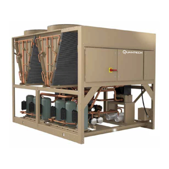
- Page 1 FORM QTC3-EG6 (1118) MODEL QTC3 AIR-COOLED SCROLL CHILLERS 55 – 230 TON 195 – 800 kW 60 Hz R-410A LD18971a...
- Page 2 40 = 380-3-60 46 = 460-3-60 58 = 575-3-60 REFRIGERANT = R-410A QTC3 = QUANTECH CHILLER MODEL NUMBER Approvals • ASME Boiler and Pressure Vessel Code – Section Vlll Division 1. • AHRI Standard 550/590. • UL 1995 – Heating and Cooling Equipment •...
-
Page 3: Table Of Contents
ELECTRICAL DATA WITHOUT PUMPS ....................... 44 WIRING DIAGRAM ..............................48 USER CONTROL WIRING ............................ 50 NOTES ................................... 51 APPLICATION DATA ............................. 53 GUIDE SPECIFICATIONS ............................. 55 Performance data provided in this document was created in accordance with Quantech software: YW version 17.06 QUANTECH... - Page 4 FORM QTC3-EG6 (1118) THIS PAGE INTENTIONALLY LEFT BLANK. QUANTECH...
-
Page 5: Introduction
FORM QTC3-EG6 (1118) Introduction Quantech™ is proud to present the Model QTC3 Air-Cooled Scroll Chiller. FEATURES AND BENEFITS Installation The QTC3 chiller arrives as a factory-assembled package ready to be installed outdoors, either on the roof or at ground level. The air-cooled condensers eliminate the capital, installation and maintenance costs of a cooling-tower circuit. - Page 6 30%, the QTC3 chiller provides the most ecologically friendly equipment. Part- nered with its low-sound properties for noise pollution prevention, this chiller is a true earth-friendly offering. QUANTECH...
- Page 7 The condenser heat exchangers are light enough that no crane is required for replacement. And when it’s time to clean them, city tap water, with water pressure typical of a spray from a common garden hose, is all that’s needed. QUANTECH...
-
Page 8: Equipment Overview
The compact, high efficiency Brazed Plate Heat Exchanger (BPHE) is constructed with 316L stainless steel corrugated channel plates with a filler material between each plate. It offers excellent heat transfer performance with a compact size and low weight, reducing structural steel requirements on the job site. QUANTECH... - Page 9 The evaporator is equipped with a thermostat-controlled heater. The heater provides freeze protection for the evaporator down to -20°F (-29°C) ambient. The evaporator is covered with 3/4” flexible, closed-cell, foam insulation (K=0.25). A factory-wired flow switch is standard, installed in a pipe section at the outlet of the evaporator. QUANTECH...
- Page 10 They are directly driven by independent motors, and positioned for vertical air discharge. The fan guards are constructed of heavy-gauge, rust-resistant, coated steel. All blades are statically and dynamically balanced for vibration-free operation. QUANTECH...
- Page 11 TRANSFORMER TERMINAL BLOCK LD18429a FUSES The operating program is stored in non-volatile memory (EPROM), so power failures and battery discharge will not require reprogramming the chiller. Programmed setpoints are retained in lithium battery-backed RTC memory for 5 years minimum. QUANTECH...
- Page 12 ENTRY section allows entering setpoints or modifying system values. SETPOINTS updating can be performed to: • Chilled liquid temperature setpoint and range. • Remote reset temperature range. • Set daily schedule/holiday for start/stop. • Manual override for servicing. • Low and high ambient cut-outs. QUANTECH...
- Page 13 • Automatic or manual system lead/lag control. • Lead system definition. • Compressor starts & operating hours (each compressor). • Status of hot gas valves, evaporator heater and fan operation. • Run permissive status. • Number of compressors running. QUANTECH...
- Page 14 • Compressor motor starting contactors per l.E.C. • Control power terminals to accept incoming for 115-1-60 control power. • Fan contactors & overload current protection. CONTACTORS DISCONNECT SWITCH FUSE FUSE CONTACTORS CONTACTORS CONTACTORS XTBF1 COMPRESSOR COMPRESSOR GROUND CONTACTORS CONTACTORS LD18430A QUANTECH...
-
Page 15: Unit Components
FORM QTC3-EG6 (1118) Unit Components MICROCHANNNEL FAN DECK COILS COIL HEADERS HYDRO-KIT PUMPS AND CONTROL AND MOTORS POWER (OPTIONAL) PANELS COMPRESSORS FORMED STEEL BASE BRAZED PLATE RAILS EVAPORATOR LD18426 FIGURE 1 - QTC3 UNIT COMPONENTS QUANTECH... -
Page 16: Accessories And Options
Hot Gas By-Pass – Permits continuous, stable operation at capacities below the minimum step of compressor unloading to as low as 5% capacity (depending on both the unit and operating conditions) by introducing an artificial load on the evaporator. Hot gas by-pass is installed on only refrigerant system #1. QUANTECH... - Page 17 Enclosure Panels (Unit) – Tamperproof enclosure panels prevent unauthorized access to units. Enclosure panels can provide an aesthetically pleasing alternative to expensive fenc- ing. Additionally, for proper head pressure control, Quantech recommends the use of Con- denser Louvered Panels for winter applications where wind gusts may exceed five miles per hour (8 kph).
- Page 18 AHRI conditions. The fans are three-bladed for 60Hz and five-bladed for 50Hz. VIBRATION ISOLATION Vibration Isolators – Level adjusting, spring type 1” (25.4mm), 2” (50.8 mm) deflection, or neoprene isolators for mounting under unit base rails. (Field installed.) QUANTECH...
- Page 19 FORM QTC3-EG6 (1118) THIS PAGE INTENTIONALLY LEFT BLANK. QUANTECH...
-
Page 20: Design Parameters
1. For leaving liquid temperature below 40°F (4°C) (to 10°F [-12°C]), optional low temperature glycol kit re- quired. Contact your nearest Quantech Office for application requirements. 2. For leaving liquid temperature higher than 55°F (13°C), contact the nearest Quantech Office for applica- tion guidelines. -
Page 21: Water Pressure Drop
FORM QTC3-EG6 (1118) Water Pressure Drop QTC3 EVAPORATOR PRESSURE DROP CURVE Water Flow Rate (gpm) LD28161 EVAPORATOR MODELS QTC3055THE, QTC3060THE, QTC3070TSE QTC3075TSE QTC3085TSE, QTC3095TSE, QTC3090THE, QTC3100THE, QTC3120THE QTC3079THE, QTC3125TSE QTC3160TSE, QTC3150THE QTC3110TSE, QTC3140TSE, QTC3129THE QTC3170THE QTC205THE QTC225THE QUANTECH... -
Page 22: Physical Data And Nominal Ratings
Water Volume, Gallons 13.2 10.0 13.2 10.0 Maximum Water Side Pressure, PSIG Maximum Refrigerant Side Pressure, PSIG Minimum Chiller Water Flow Rate, Maximum Chiller Water Flow Rate, Water Connections Size, Inches * Side extension kit (standard), evaporator nozzle remains 3”. QUANTECH... - Page 23 12.6 14.3 Maximum Water Side Pressure, PSIG Maximum Refrigerant Side Pressure, PSIG Minimum Chiller Water Flow Rate, GPM Maximum Chiller Water Flow Rate, GPM Water Connections 5" 5" Size, Inches * Side extension kit (standard), evaporator nozzle remains 3”. QUANTECH...
-
Page 24: Part Load Ratings
95.0 50.0 101.5 64.3 71.4 15.0 86.1 86.5 88.5 89.3 10.7 33.3 69.5 38.9 59.9 18.3 57.0 64.5 45.4 75.5 14.4 16.7 34.5 18.2 55.0 19.2 43.0 47.4 34.4 64.7 15.1 IPLV 15.6 13.9 16.0 55.0 18.7 IPLV 14.5 QUANTECH... - Page 25 IPLV 15.7 20.2 44.6 27.4 55.0 17.4 IPLV 15.6 QTC3120THE COMPR. AMBIENT % DISPL. TONS UNIT EER (°F) 100.0 116.0 112.0 95.0 10.3 75.0 94.6 76.8 83.9 12.6 50.0 67.2 43.5 69.7 16.0 25.0 34.9 18.3 55.0 19.3 IPLV 15.7 QUANTECH...
-
Page 26: Unit Dimensions
Recommended minimum clearances: Side to wall – 6'; rear to wall – 6'; control panel to end wall – 4'0''; top – no obstructions allowed; distance between adjacent units – 10'. No more than one adjacent wall may be higher than the unit. QUANTECH... - Page 27 Recommended minimum clearances: Side to wall – 6'; rear to wall – 6'; control panel to end wall – 4'0''; top – no obstructions allowed; distance between adjacent units – 10'. No more than one adjacent wall may be higher than the unit. QUANTECH...
- Page 28 Recommended minimum clearances: Side to wall – 6'; rear to wall – 6'; control panel to end wall – 4'0''; top – no obstructions allowed; distance between adjacent units – 10'. No more than one adjacent wall may be higher than the unit. QUANTECH...
- Page 29 Recommended minimum clearances: Side to wall – 6'; rear to wall – 6'; control panel to end wall – 4'0''; top – no obstructions allowed; distance between adjacent units – 10'. No more than one adjacent wall may be higher than the unit. QUANTECH...
- Page 30 Recommended minimum clearances: Side to wall – 6'; rear to wall – 6'; control panel to end wall – 4'0''; top – no obstructions allowed; distance between adjacent units – 10'. No more than one adjacent wall may be higher than the unit. QUANTECH...
- Page 31 Recommended minimum clearances: Side to wall – 6'; rear to wall – 6'; control panel to end wall – 4'0''; top – no obstructions allowed; distance between adjacent units – 10'. No more than one adjacent wall may be higher than the unit. QUANTECH...
- Page 32 Recommended minimum clearances: Side to wall – 6'; rear to wall – 6'; control panel to end wall – 4'0''; top – no obstructions allowed; distance between adjacent units – 10'. No more than one adjacent wall may be higher than the unit. QUANTECH...
-
Page 33: Isolator Locations
FORM QTC3-EG6 (1118) Isolator Locations FOUR FAN ISOLATOR LOCATIONS FOR QTC3055THE, QTC3060THE, QTC3079THE LD18437 FOUR FAN ISOLATOR LOCATIONS FOR QTC3070TSE, QTC3075TSE, QTC3085TSE LD18438 All dimensions are inches unless otherwise specified. Dimensions indicate isolator mounting centerlines. QUANTECH... - Page 34 FORM QTC3-EG6 (1118) Isolator Locations (Cont'd) FIVE & SIX FAN ISOLATOR LOCATIONS FOR QTC3095TSE, QTC3110TSE, QTC3090THE, QTC3100THE LD18439 EIGHT FAN ISOLATOR LOCATIONS FOR QTC3125TSE, QTC3140TSE, QTC3129THE LD18440 VIEW All dimensions are inches unless otherwise specified. Dimensions indicate isolator mounting centerlines. QUANTECH...
- Page 35 TEN FAN ISOLATOR LOCATIONS FOR QTC3160TSE, QTC3150THE, QTC3170THE LD18441 All dimensions are inches unless otherwise specified. Dimensions indicate isolator mounting centerlines. VIEW TWELVE FAN ISOLATOR LOCATIONS QTC3205THE, QTC3225THE VIEW LD21040 All dimensions are inches unless otherwise specified. Dimensions indicate isolator mounting centerlines. QUANTECH...
-
Page 36: Isolator Details
1.7 (43) 1318 (149) 3342 (1516) PINK/BLACK Y2RSI-2D-2640N 2640 (1197) 1.5 (38) 1854 (209) 4283 (1943) PINK/GRAY PINK/GRAY/ Y2RSI-2D-2870N 3080 (1397) 1.5 (38) 2004 (226) 4629 (2100) ORANGE PINK/GRAY/DK Y2RSI-2D-3280N 3740 (1696) 1.8 (46) 2134 (241) 4930 (2236) BROWN QUANTECH... - Page 37 1020 (463) 1.020 (46) BLACK CP2-1D-1350 1350 (612) 1.32 (34) DK. PURPLE CP2-1D-1800 1800 (816) 1.02 (26) DK. GREEN CP2-1D-2400 2400 (1089) 0.9 (23) GRAY CP2-1D-2720 2720 (1234) 0.77 (20) WHITE CP2-1D-3570N 3570 (1619) 0.88 (22) GRAY / RED QUANTECH...
- Page 38 1100 (499) 0.5 (12) RATED CAPACITY RATED DEFLECTION RD4 MODEL NUMBER DURO (± 5) LBS (KG) IN (MM) RD4-BROWN-WR 1500 (680) 0.5 (12) RD4-BRICK RED-WR 2250 (1021) 0.5 (12) RD4-LIME-WR 3000 (1361) 0.5 (12) RD4-CHARCOAL-WR 4000 (1814) 0.5 (12) QUANTECH...
-
Page 39: Electrical Notes
This disconnect is not intended to be a Load Break Device. 9. Field Wiring by others which complies to the National Electrical Code & Local Codes. QUANTECH... - Page 40 MINIMUM NON FUSED RATED LOAD AMPS S.P. WIRE SINGLE POINT WIRING UNIT MTD SERV SW UNIT MOUNTED SERVICE (NON-FUSED DISCONNECT SWITCH) LOCKED ROTOR AMPS VOLTAGE CODE -17 = 208-3-60 -28 = 230-3-60 -40 = 380-3-60 -46 = 460-3-60 -58 = 575-3-60 QUANTECH...
-
Page 41: Variable Speed Pump Electrical Data
14.6 3600 16.2 13.5 28.7 22.5 1800 3600 23.2 18.4 11.1 3600 16.2 13.5 28.7 22.5 1800 15.4 3600 12.9 36.4 10.9 18.2 14.6 3600 3600 15.4 3600 28.3 15.1 1800 28.3 15.1 CONTROL TRANSFORMER LOAD VOLT 14.4 13.0 QUANTECH... -
Page 42: Wiring Lugs
(1) 6 - 350 NOTE: Alternate lugs are provided in the panel for field electricians and contractors, should there be a need for other lug arrangements that the installed lugs on the non-fused disconnect switch and circuit breaker panels. QUANTECH... - Page 43 (1) 250 - 500 NOTE: Alternate lugs are provided in the panel for field electricians and contractors, should there be a need for other lug arrangements that the installed lugs on the non-fused disconnect switch and circuit breaker panels. QUANTECH...
-
Page 44: Electrical Data Without Pumps
NOTES: 1. Reference PIN 59 on the unit panel for pump models. 2. Use this table along with Pump Electrical Data on page 41 to determine electrical data of the unit plus the pump. 3. Does not include the Control Transformer on page 41. QUANTECH... - Page 45 NOTES: 1. Reference PIN 59 on the unit panel for pump models. 2. Use this table along with Pump Electrical Data on page 41 to determine electrical data of the unit plus the pump. 3. Does not include the Control Transformer on page 41. QUANTECH...
- Page 46 NOTES: 1. Reference PIN 59 on the unit panel for pump models. 2. Use this table along with Pump Electrical Data on page 41 to determine electrical data of the unit plus the pump. 3. Does not include the Control Transformer on page 41. QUANTECH...
- Page 47 NOTES: 1. Reference PIN 59 on the unit panel for pump models. 2. Use this table along with Pump Electrical Data on page 41 to determine electrical data of the unit plus the pump. 3. Does not include the Control Transformer on page 41. QUANTECH...
-
Page 48: Wiring Diagram
FORM QTC3-EG6 (1118) Wiring Diagram QUANTECH... - Page 49 FORM QTC3-EG6 (1118) Wiring Diagram (Cont'd) LD18444 QUANTECH...
-
Page 50: User Control Wiring
INTERNAL 120 VAC WIRING TO F1 FUSE Normally jumpered. Can be used as INTERNAL 120 VAC WIRING (TYPICALLY FROM CONTROL TRANSFORMER) EMERGENCY STOP contacts from an INTERNAL NEUTRAL WIRING external source. INTERNAL NEUTRAL WIRING (TYPICALLY FROM CONTROL TRANSFORMER) INTERNAL NEUTRAL WIRING XTBC2 QUANTECH... -
Page 51: Notes
(INCLUDING COIL SUPPRESSOR) -KFOL FAN OVERLOAD WIRING AND ITEMS SHOWN THUS -KFS RELAY FAN SPEED ARE STANDARD ACCESSORIES (INCLUDING COIL SUPPRESSOR) QUANTECH (INCLUDING COIL SUPPRESSOR) ITEMS THUS ENCLOSED FORM COMPRESSOR MOTOR COMPONTENTS OR SETS OF COMPONENTS MOTOR FAN MOTOR PUMP NOT USED... - Page 52 This common point of isolation is not supplied by Quantech. The voltage free contacts are rated at 100VA. All inductive devices {relays} switch by the Quantech voltage free contacts must have their coil suppressed using standard r/c suppressors.
-
Page 53: Application Data
A one-piece concrete slab with footers extending below the frost line is highly recom- mended. Additionally, the slab should not be tied to the main building foundation as noises will telegraph. QUANTECH... - Page 54 VARIABLE PRIMARY FLOW Quantech recommends a maximum 10% per minute flow rate of change, based on design flow, for variable primary flow applications. Eight to 10 gallons per chiller ton (8.6 to 10.8 liter per cooling kW) is recommended for the system liquid volume. Insufficient system volume and rapid flow changes can cause control problems or can even cause chiller shutdowns.
-
Page 55: Guide Specifications
10. Conform to Intertek Testing Services for construction of chillers and provide ETL/ cETL Listed Mark. B. Factory Run Test: Chiller shall be pressure-tested, evacuated and fully charged with re- frigerant and oil, and shall be factory operational run tested with water flowing through the vessel. QUANTECH... - Page 56 1. Discharge Pressure Transducers: Permits unit to sense and display discharge pres- sure. 2. Suction Pressure Transducers: Permits unit to sense and display suction pressure. 3. High Ambient Control: Allows units to operate when the ambient temperature is above 115°F (46°C). Includes discharge pressure transducers. QUANTECH...
- Page 57 0.26k ([BTU/ HR-Ft2 -°F]/in.) maximum. 4. Water nozzles shall be provided with grooves for field provided ANSI/AWWA C-606 mechanical couplings. 5. Evaporator shall include vent and drain fittings and thermostatically controlled heat- ers to protect to -20°F (-29°C) ambient in off-cycle. QUANTECH...
- Page 58 (RTC) memory for minimum 5 years. 4. Forty character liquid crystal display, descriptions in English (or Spanish, French, Italian, or German), numeric data in English (or Metric) units. Sealed keypad with sections for Setpoints, Display/Print, Entry, Unit Options & clock, and On/Off Switch. QUANTECH...
- Page 59 Separate disconnecting means and/or external branch circuit protection (by Contractor) required per appli- cable local or national codes. B. Compressor, control and fan motor power wiring shall be located in an enclosed panel or routed through liquid tight conduit. QUANTECH...
- Page 60 FORM QTC3-EG6 (1118) Guide Specifications (Cont'd) 2.07 ACCESSORIES AND OPTIONS Some accessories and options supersede standard product features. Your Quantech rep- resentative will be pleased to provide assistance. A. Microprocessor controlled, Factory installed Across-the-Line type compressor motor starters as standard.
- Page 61 D. Electrical: coordinate electrical requirements and connections for all power feeds with electrical contractor (Division 16). E. Controls: coordinate all control requirements and connections with controls contractor. F. Finish: installing contractor shall paint damaged and abraded factory finish with touch- up paint matching factory finish. QUANTECH...
- Page 62 Printed on recycled paper Form QTC3-EG6 (1118) Supersedes: QTC3-EG6 (618) © 2018 P.O. Box 423, Milwaukee, WI 53201 Printed in USA Issued on 11/30/18...
Need help?
Do you have a question about the 3070TSE and is the answer not in the manual?
Questions and answers