
Related Manuals for Quantech QWC3


Summary of Contents for Quantech QWC3
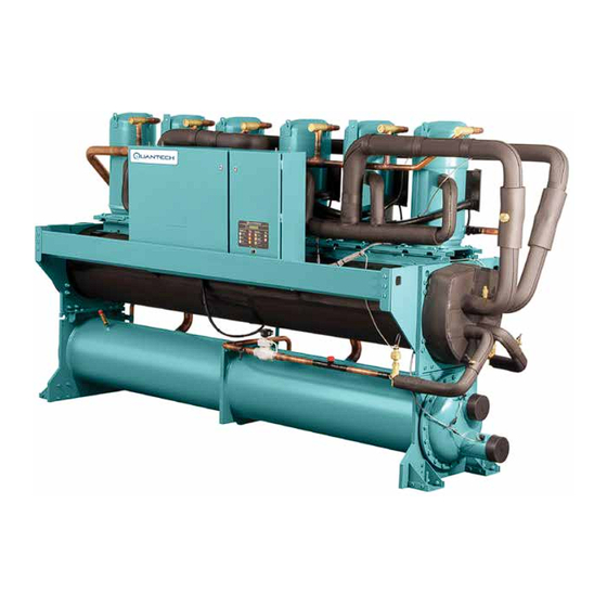
- Page 1 FORM QWC3-EG1 (217) MODEL QWC3 WATER-COOLED SCROLL LIQUID CHILLER 50 – 200 TONS 60Hz R-410a...
- Page 2 58 = 575-3-60 150T 170T REFRIGERANT = R-410a 200T QWC3 = QUANTECH CHILLER WATER COOLED SCROLL Approvals • ASME Boiler and Pressure Vessel Code –Section Vlll Division 1 • AHRI Standard 550/590 and 551/591 • c/U.L. – Underwriters Laboratory • ASHRAE 15 – Safety Code for Mechanical Refrigeration • ASHRAE Guideline 3 –...
-
Page 3: Table Of Contents
FORM QWC3-EG1 (217) Table of Contents EQUIPMENT OVERVIEW ............................5 MICROPROCESSOR CONTROLS ......................... 8 ACCESSORIES AND OPTIONS ........................... 11 REFRIGERANT FLOW DIAGRAM ........................14 DESIGN PARAMETERS ............................15 PRESSURE DROP CURVES ..........................16 SELECTION DATA ..............................18 APPLICATION DATA ............................. 22 RATINGS ................................ - Page 4 FORM QWC3-EG1 (217) THIS PAGE INTENTIONALLY LEFT BLANK. QUANTECH...
-
Page 5: Equipment Overview
Microcomputer Control Center mounted on a rugged steel base. The units are produced at an ISO 9001 registered facility. The QWC3 chillers are rated in accordance with AHRI Standard 550/590. - Page 6 AHRI CERTIFICATION PROGRAM QWC3 chillers have been tested and certified by Air-Conditioning, Heating and Refrigera- tion Institute (AHRI) in accordance with the latest edition of AHRI Standard 550/590 (I-P).
- Page 7 FORM QWC3-EG1 (217) Equipment Overview (Cont'd) POWER AND CONTROL PANELS All controls and motor starting equipment necessary for unit operation shall be factory wired and function tested. The panel enclosures shall be designed to NEMA 1 (IP 32) and manufactured from powder-painted galvanized steel.
-
Page 8: Microprocessor Controls
FORM QWC3-EG1 (217) Microprocessor Controls MICROPROCESSOR CONTROLS The control section shall contain: • On/Off rocker switch • Microcomputer keypad and display • Microprocessor board • I/O expansion board • Relay boards • 24V fused power-supply board The control display shall include: • Liquid Crystal Display with Light Emitting Diode backlighting for outdoor viewing... - Page 9 FORM QWC3-EG1 (217) Microprocessor Controls (Cont'd) • Low liquid temperature cutout • Low suction pressure cutout • High discharge pressure cutout • Anti-recycle timer (compressor start cycle time) • Anti-coincident timer (delay compressor starts) Unit section to: • Set time • Set unit options...
- Page 10 FORM QWC3-EG1 (217) Microprocessor Controls (Cont'd) The standard controls shall include: brine chilling, automatic pumpdown, run signal con- tacts, demand load limit form external building automation system input, remote reset liquid temperature reset input, unit alarm contacts, chilled liquid pump control, automatic reset after power failure, and automatic system optimization to match operating condi- tions.
-
Page 11: Accessories And Options
FORM QWC3-EG1 (217) Accessories and Options All accessories and options are factory installed unless otherwise noted. POWER OPTIONS Single Point Supply Terminal Block – The standard power wiring connection on all models is a single point power connection to a factory provided terminal block. Compo- nents included are the enclosure, terminal-block and interconnecting wiring to the com- pressors. - Page 12 FORM QWC3-EG1 (217) Accessories and Options (Cont'd) Differential Pressure Switch – An alternative option to the paddle-type flow switch. 3-45 PSIG (0.2-3 bar) range with ¼” NPTE pressure connections. (Field Mounted) Pressure Vessel Codes – Evaporators and condensers are be supplied (Standard) in con- formance with the A.S.M.E.
- Page 13 FORM QWC3-EG1 (217) Accessories and Options (Cont'd) VIBRATION ISOLATION Elastomeric Isolation – Recommended for normal in stallations. Provides very good per- formance in most applications for the least cost. (Field-Mounted) 1 Inch Spring Isolators – Level adjustable, spring and cage type isolators for mounting under the unit base rails.
-
Page 14: Refrigerant Flow Diagram
FORM QWC3-EG1 (217) Refrigerant Flow Diagram Low-pressure liquid refrigerant enters the evaporator tubes and is evaporated and super- heated by the heat energy absorbed from the chilled liquid passing through the evaporator shell. Low-pressure vapor enters the compressor where pressure and superheat are in- creased. -
Page 15: Design Parameters
(18) (54) NOTES: 1. For leaving temperature below 40°F (4.4°C), optional brine chilling kit required. Minimum with kit is 15°F (-9.4°C). 2. For leaving water temperature higher than 50°F (10°C), contact the nearest Quantech Sales Representative for application guidelines. QUANTECH... -
Page 16: Pressure Drop Curves
FORM QWC3-EG1 (217) Pressure Drop Curves QWC3 Evaporator Pressure Drop (English Units) Water Flow Rate (GPM) LD18404A 10.0 EVAPORATOR QWC3 MODEL NUMBER 050TSE, 060TSE, 070TSE, 080TSE 060THE, 090TSE 100TSE, 115TSE 070THE, 080THE, 090THE, 115THE, 130TSE 095THE, 150TSE 130THE, 150THE, 200TSE QWC3 Evaporator Pressure Drop (SI Units) 100.0... - Page 17 FORM QWC3-EG1 (217) Pressure Drop Curves (Cont'd) QWC3 Condenser Pressure Drop (English Units) 100.0 10.0 1000 Water Flow Rate (GPM) LD18406A EVAPORATOR QWC3 MODEL NUMBER 050TSE, 060TSE, 070TSE, 080TSE 060THE, 090TSE 100TSE, 115TSE 070THE, 080THE, 090THE, 115THE, 130TSE 095THE, 150TSE...
-
Page 18: Selection Data
Selection Data GUIDE TO SELECTION Complete water chilling capacity ratings for QWC3 chillers are shown on the following pages to cover the majority of job requirements. For any application beyond the scope of this Engineering Guide, consult your nearest Quantech Sales Representative. - Page 19 FORM QWC3-EG1 (217) Selection Data (Cont'd) 5. Ethylene Glycol Correction Factors – The following factors are to be applied to the standard ratings for units cooling ethylene glycol. ETHYLENE GLYCOL PRESS FREEZE %WEIGHT TONS COMPR KW DROP POINT 0.993 1.002 1.029...
- Page 20 Condenser Water Range (ºF) SAMPLE SELECTION Water Cooled Chiller (QWC3) GIVEN – Chill 200 GPM of water from 56ºF to 44ºF and 0.0001 evaporator fouling factor with 85ºF to 95ºF condensing water available. The fouling factor is 0.0005 for the con- denser.
- Page 21 FORM QWC3-EG1 (217) Selection Data (Cont'd) 3. Determine the average full load kW and EER at 100 Tons. X (84.4) = 77.6 kW 108.8 Tons x 12 100 x 12 EER = = 15.5 77.6 4. Determine the cond. Heat rejection as follows: Heat Rejection (MBH) = (Tons x 12) + (kW x 3.415)
-
Page 22: Application Data
FORM QWC3-EG1 (217) Application Data UNIT LOCATION Chillers are designed for indoor installation. Units should be located away from noise-crit- ical areas. Service clearance must be allowed and include space for remov ing condenser tubes. A doorway or window can sometimes provide space for tube removal. Units should be installed indoors where they are not exposed to rain or water splash. - Page 23 Quantech liquid chiller units are factory wired for optimum reliability. Therefore the unit controls must not be modified without ex pressed written consent by Quantech. The use of a simple switch or timer from a remote point is permitted; but it must be connected to the unit panel at points expressly indicated for that purpose.
-
Page 24: Ratings
FORM QWC3-EG1 (217) Ratings - Standard Efficiency MODEL: QWC3050TSE IPLV= 21.3 ENTERING CONDENSER WATER TEMPERATURE (°F) LCWT 75.0 85.0 95.0 TONS TONS TONS (°F) 40.0 50.7 33.9 724.0 17.9 48.1 37.7 705.0 15.3 45.3 42.0 686.0 12.9 42.0 52.6 34.1 747.0... - Page 25 FORM QWC3-EG1 (217) Ratings - Standard Efficiency (Cont'd) MODEL: QWC3090TSE IPLV= 21.6 ENTERING CONDENSER WATER TEMPERATURE (°F) LCWT 75.0 85.0 95.0 TONS TONS TONS (°F) 40.0 84.4 57.1 1207.0 17.7 80.1 63.1 1176.0 15.2 75.5 70.1 1145.0 12.9 42.0 87.5 57.4...
- Page 26 FORM QWC3-EG1 (217) Ratings - Standard Efficiency (Cont'd) MODEL: QWC3150TSE IPLV= 23.6 ENTERING CONDENSER WATER TEMPERATURE (°F) LCWT 75.0 85.0 95.0 TONS TONS TONS (°F) 40.0 142.3 91.1 2018.0 18.7 134.2 104.9 1968.0 15.4 125.9 120.9 1923.0 12.5 42.0 147.4 90.9...
- Page 27 FORM QWC3-EG1 (217) Ratings- High Efficiency MODEL: QWC3060THE IPLV= 21.5 ENTERING CONDENSER WATER TEMPERATURE (°F) LCWT 75.0 85.0 95.0 TONS TONS TONS (°F) 40.0 61.9 41.1 883.0 18.1 58.8 45.9 862.0 15.4 55.4 51.1 839.0 13.0 42.0 64.1 41.3 910.0 18.6...
- Page 28 FORM QWC3-EG1 (217) Ratings - High Efficiency (Cont'd) MODEL: QWC3095THE IPLV= 21.8 ENTERING CONDENSER WATER TEMPERATURE (°F) LCWT 75.0 85.0 95.0 TONS TONS TONS (°F) 40.0 93.8 61.3 1334.0 18.4 89.1 68.5 1302.0 15.6 84.0 76.4 1268.0 13.2 42.0 97.2 61.6...
-
Page 29: Part Load Ratings
FORM QWC3-EG1 (217) Part Load Ratings ENGLISH STANDARD EFFICIENCY (SE) QWC3050TSE QWC3060TSE QWC3070TSE QWC3080TSE TONS KW TONS KW TONS KW TONS KW LOAD LOAD LOAD LOAD 100.0 51.6 37.9 16.3 100.0 59.9 45.7 15.7 100.0 67.8 53.6 15.2 100.0 76.6 58.3... -
Page 30: Physical Data
FORM QWC3-EG1 (217) Physical Data STANDARD EFFICIENCY (SE) QWC3 050TSE 060TSE 070TSE 080TSE 090TSE 100TSE 115TSE 130TSE 150TSE 170TSE 200TSE GENERAL UNIT DATA Nominal Unit 51.6 59.9 67.8 76.6 85.8 92.7 110.4 127.4 144.0 167.7 199.6 Capacity (Tons) Number of... - Page 31 FORM QWC3-EG1 (217) Physical Data HIGH EFFICIENCY (HE) QWC3 060THE 070THE 080THE 090THE 095THE 115THE 130THE 150THE GENERAL UNIT DATA Nominal Unit Capacity 63.2 82.4 92.6 95.8 117.2 132.1 148.5 (Tons) Number of Independent Refrigerant Circuits Refrigerant Charge, R-410A, Ckt 1/Ckt. 2...
-
Page 32: Isolator Selection Data
FORM QWC3-EG1 (217) Isolator Selection Data CONTROL PANEL MODEL ELASTOMERIC 1” SPRING 2" SPRING EFFICIENCY QWC3 ISOLATOR ISOLATOR ISOLATOR RD-4 Brick Red CP-1D-1360 White Red/Black 050T RD-4 Brick Red CP-1D-1360 White Pink 060T RD-4 Brick Red CP-1D-1785N Gray/Red Pink 070T... -
Page 33: Isolator Information
FORM QWC3-EG1 (217) Isolator Information ELASTOMERIC ISOLATOR MOLDED DURULENE MOLDED DURULENE Ø = AD Thru Typ 2 Places R = 0.280 Slot Typ 2 Places LD17304 DIMENSION DATA (INCHES) MOUNT TYPE RD1-WR 3.13 1.75 1.25 2.38 0.34 0.19 5/16-18 UNC X 3/4 1.25... - Page 34 FORM QWC3-EG1 (217) Isolator Information (Cont'd) ONE INCH DEFLECTION SPRING ISOLATOR 5/8" H" C" T" B" L" D" W" LD18408 MOUNT DIMENSION DATA (INCHES) TYPE 7-3/4 6-1/2 4-3/4 5-5/8 10-1/2 9-1/4 7-3/4 9/16 RATED CAPACITY (FOR UNITS WITH ALL LOAD...
- Page 35 FORM QWC3-EG1 (217) Isolator Information (Cont'd) TWO INCH DEFLECTION SPRING ISOLATOR 2-3/ 2-3/4 3/ GAP TYP . (4) ST O P & 8-3/8 OPER. HEIGHT LD18409 WEIGHT RANGE WEIGHT RANGE MODEL NUMBER ISOLATOR COLOR (LBS) (KGS) Y2RSI-2D-460 GREEN Up thru 391...
-
Page 36: Sound Data
FORM QWC3-EG1 (217) Sound Data 60 HZ MODELS, BASE UNITS AHRI 575 SOUND PRESSURE LEVELS (DB RE: 20 MICROPASCALS) STANDARD EFFICIENCY 1000 2000 4000 8000 QWC3050TSE QWC3060TSE QWC3070TSE QWC3080TSE QWC3090TSE QWC3100TSE QWC3115TSE QWC3130TSE QWC3150TSE QWC3170TSE QWC3200TSE AHRI 575 SOUND PRESSURE LEVELS (DB RE: 20 MICROPASCALS) - Page 37 FORM QWC3-EG1 (217) Sound Data (Cont'd) 60 HZ MODELS, COMPRESSOR BLANKETS INSTALLED AHRI 575 SOUND PRESSURE LEVELS (DB RE: 20 MICROPASCALS) STANDARD EFFICIENCY 1000 2000 4000 8000 QWC3050TSE QWC3060TSE QWC3070TSE QWC3080TSE QWC3090TSE QWC3100TSE QWC3115TSE QWC3130TSE QWC3150TSE QWC3170TSE QWC3200TSE AHRI 575 SOUND PRESSURE LEVELS (DB RE: 20 MICROPASCALS)
-
Page 38: Unit Dimensions - Four Compressor
FORM QWC3-EG1 (217) Unit Dimensions - Four Compressor STANDARD EFFICIENCY (SE) QWC3 050TSE 060TSE 070TSE 080TSE 090TSE 100TSE 115TSE 130TSE 150TSE 34 5/8 34 5/8 33 13/16 33 13/16 33 13/16 33 13/16 33 13/16 33 13/16 34 13/16 64 15/32... - Page 39 FORM QWC3-EG1 (217) Unit Dimensions - Four Compressor (Cont'd) NOTES: 1. Recommended service clearances Rear to wall: 20" (508mm) Front to wall: 36" (915mm) ORIGIN Top: 43" (1092mm) Tube cleaning and removal: 132" (3353mm) either end 2. Relief valve connection sizes Low side (suction line): 1/2"...
- Page 40 FORM QWC3-EG1 (217) Unit Dimensions - Five & Six Compressor STANDARD EFFICIENCY (SE) HIGH EFFICIENCY (HE) QWC3 170TSE 200TSE 095THE 130THE 34 13/16 34 13/16 35 1/16 34 13/16 77 9/32 77 9/32 72 5/32 77 19/32 – – –...
- Page 41 FORM QWC3-EG1 (217) Unit Dimensions - Five & Six Compressor (Cont'd) NOTES: 1. Recommended service clearances Rear to wall: 20" (508mm) Front to wall: 36" (915mm) Top: 43" (1092mm) Tube cleaning and removal: 132" (3353mm) either end 2. Relief valve connection sizes Low side (suction line): 1/2"...
-
Page 42: Single Point Electrical Data
FORM QWC3-EG1 (217) Single Point Electrical Data STANDARD EFFICIENCY WITHOUT OPTIONAL EXTERNAL COMPRESSOR OVERLOADS LUGS PER PHASE MINIMUM MIN DUAL MAX DUAL TERMINAL BLOCK MODEL MIN N/F VOLT CIRCUIT ELEM FUSE ELEM FUSE LUG SIZE (STD) QWC3 DISC SW AMPS (MCA) &... - Page 43 FORM QWC3-EG1 (217) Single Point Electrical Data (Cont'd) STANDARD EFFICIENCY WITHOUT OPTIONAL EXTERNAL COMPRESSOR OVERLOADS SYSTEM # 1 SYSTEM # 2 MODEL COMPR 1 COMPR 2 COMPR 3 COMPR 1 COMPR 2 COMPR 3 QWC3 48.5 48.5 48.5 51.3 48.5 48.5...
- Page 44 FORM QWC3-EG1 (217) Single Point Electrical Data (Cont'd) HIGH EFFICIENCY WITHOUT OPTIONAL EXTERNAL COMPRESSOR OVERLOADS MINIMUM MIN DUAL MAX DUAL MODEL TERMINAL BLOCK LUG SIZE (STD) VOLT CIRCUIT ELEM FUSE ELEM FUSE QWC3 DISC AMPS (MCA) & MIN CB & MAX CB QTY/ ∅...
- Page 45 FORM QWC3-EG1 (217) Single Point Electrical Data (Cont'd) HIGH EFFICIENCY WITHOUT OPTIONAL EXTERNAL COMPRESSOR OVERLOADS SYSTEM # 1 SYSTEM # 2 MODEL COMPR 1 COMPR 2 COMPR 3 COMPR 1 COMPR 2 COMPR 3 QWC3 57.7 57.7 57.7 57.7 57.7 57.7...
- Page 46 FORM QWC3-EG1 (217) Single Point Electrical Data (Cont'd) STANDARD EFFICIENCY WITH OPTIONAL EXTERNAL COMPRESSOR OVERLOADS LUGS PER PHASE MINIMUM DUAL DUAL DISCONNECT SWITCH CIRCUIT BREAKER CIRCUIT MODEL MIN N/F ELEM VOLT ELEM AMPS LUG SIZE (OPT) LUG SIZE (OPT) QWC3 DISC SW FUSE &...
- Page 47 FORM QWC3-EG1 (217) Single Point Electrical Data (Cont'd) STANDARD EFFICIENCY WITH OPTIONAL EXTERNAL COMPRESSOR OVERLOADS SYSTEM # 1 SYSTEM # 2 MODEL COMPR 1 COMPR 2 COMPR 3 COMPR 1 COMPR 2 COMPR 3 QWC3 32.7 32.7 32.7 32.7 28.4 28.4...
- Page 48 FORM QWC3-EG1 (217) Single Point Electrical Data (Cont'd) HIGH EFFICIENCY WITH OPTIONAL EXTERNAL COMPRESSOR OVERLOADS LUGS PER PHASE MINIMUM DUAL DUAL CIRCUIT MODEL MIN N/F DISCONNECT SWITCH CIRCUIT BREAKER ELEM VOLT HZ ELEM AMPS QWC3 DISC SW LUG SIZE (OPT) LUG SIZE (OPT) FUSE &...
- Page 49 FORM QWC3-EG1 (217) Single Point Electrical Data (Cont'd) HIGH EFFICIENCY WITH OPTIONAL EXTERNAL COMPRESSOR OVERLOADS SYSTEM # 1 SYSTEM # 2 MODEL COMPR 1 COMPR 2 COMPR 3 COMPR 1 COMPR 2 COMPR 3 QWC3 40.1 40.1 40.1 40.1 34.9 34.9...
- Page 50 FORM QWC3-EG1 (217) Dual Point Electrical Data STANDARD EFFICIENCY WITH EXTERNAL COMPRESSOR OVERLOADS SYSTEM 1 WIRING SYSTEM 2 WIRING MODEL MINIMUM MIN DUAL MAX DUAL MINIMUM MIN DUAL MAX DUAL VOLT HZ MIN N/F MIN N/F QWC3 CIRCUIT ELEM FUSE...
- Page 51 FORM QWC3-EG1 (217) Dual Point Electrical Data (Cont'd) STANDARD EFFICIENCY WITH EXTERNAL COMPRESSOR OVERLOADS SYSTEM # 1 SYSTEM # 2 COMPR 1 COMPR 2 COMPR 3 COMPR 1 COMPR 2 COMPR 3 MODEL CIRCUIT CIRCUIT QTY. QTY. VOLT HZ QWC3...
- Page 52 FORM QWC3-EG1 (217) Dual Point Electrical Data (Cont'd) HIGH EFFICIENCY WITH EXTERNAL COMPRESSOR OVERLOADS SYSTEM 1 WIRING SYSTEM 2 WIRING MIN DUAL MAX DUAL MIN DUAL MODEL MINIMUM MINIMUM DUAL VOLT HZ MIN N/F ELEM ELEM MIN N/F ELEM QWC3...
- Page 53 FORM QWC3-EG1 (217) Dual Point Electrical Data (Cont'd) HIGH EFFICIENCY WITH EXTERNAL COMPRESSOR OVERLOADS SYSTEM # 1 SYSTEM # 2 MODEL COMPR 1 COMPR 2 COMPR 3 COMPR 1 COMPR 2 COMPR 3 CIRCUIT CIRCUIT VOLT HZ QTY. QTY. QWC3...
-
Page 54: Electrical Notes
FORM QWC3-EG1 (217) Electrical Notes 1. Minimum Circuit Ampacity (MCA) is based on 125% of the rated load amps for the largest motor plus 100% of the rated load amps for all other loads included in the circuit, per N.E.C. Article 43024. If the optional Factory Mounted Control Transformer is provided, add the following MCA values to the electrical tables for the system providing power to the trans- former: 17, add 2.5 amps;... -
Page 55: Ground Wire Sizing
FORM QWC3-EG1 (217) Ground Wire Sizing GROUND LUG SIZING WITH OR WITHOUT OPTIONAL OVERLOADS NON FUSED DISCONNECT SWITCH OPTION RATING INCOMING WIRE GROUND WIRE 150A # 14 - 1/0 AWG # 8 - 2 AWG 150A # 2 - 4/0 AWG... -
Page 56: Typical Control Panel Wiring
FORM QWC3-EG1 (217) Typical Control Panel Wiring 4 COMPRESSOR UNITS LD21794a QUANTECH... - Page 57 FORM QWC3-EG1 (217) Typical Control Panel Wiring (Cont'd) 4 COMPRESSOR UNITS LD21794b QUANTECH...
- Page 58 FORM QWC3-EG1 (217) Typical Control Panel Wiring (Cont'd) 5 & 6 COMPRESSOR UNITS LD21795a QUANTECH...
- Page 59 FORM QWC3-EG1 (217) Typical Control Panel Wiring (Cont'd) 5 & 6 COMPRESSOR UNITS 035-21499-101 REV 1 LD21795b QUANTECH...
-
Page 60: Customer Wiring Information
FORM QWC3-EG1 (217) Customer Wiring Information FIELD PROVIDED UNIT POWER SUPPLY Terminal Block Non Fused Control Circuit Breaker Transformer Micropanel Circuit Circuit LD18414 FIGURE 1 - SINGLE POINT POWER SUPPLY CONNECTION – STANDARD UNIT QUANTECH... - Page 61 FORM QWC3-EG1 (217) Customer Wiring Information (Cont'd) FIELD PROVIDED UNIT POWER SUPPLY Circuit Circuit Breaker Breaker Control Transformer Micropanel Circuit Circuit LD18415 FIGURE 2 - DUAL POINT POWER SUPPLY CONNECTION – OPTIONAL QUANTECH...
-
Page 62: Guide Specifications
FORM QWC3-EG1 (217) Guide Specifications PART 1 – GENERAL 1.01 SCOPE A. The requirements of the General Conditions, Supplementary Conditions, Division 1, and Drawings apply to all Work herein. B. Provide Microprocessor controlled, multiple-scroll compressor, water-cooled, liquid chillers of the scheduled capacities as shown and indicated on the Drawings, including but not limited to: 1. - Page 63 FORM QWC3-EG1 (217) Guide Specifications (Cont'd) D. Warranty: Manufacturer shall Warrant all equipment and material of its manufacture against defects in workmanship and material for a period of one year from date of initial start-up or eighteen (18) months from date of shipment, whichever occurs first.
- Page 64 FORM QWC3-EG1 (217) Guide Specifications (Cont'd) 2.03 REFRIGERANT CIRCUIT COMPONENTS Each refrigerant circuit shall include: liquid line shutoff valve with charging port, low side pressure relief device, filter-drier, solenoid valve, discharge service valve, system high pressure relief device, sight glass with moisture indicator, expansion valves, and flexible, closed-cell foam insulated suction line.
- Page 65 FORM QWC3-EG1 (217) Guide Specifications (Cont'd) 4. Forty character liquid crystal display, numeric data in English (or Metric) units. Sealed keypad with sections for Setpoints, Display/Print, Entry, Unit Options & clock, and On/Off Switch. Display descriptions and membrane keypad graphics shown in English language.
- Page 66 National Electric Code and/or local codes. 2.07 ACCESSORIES AND OPTIONS Some accessories and options supersede standard product features. Your Quantech Sales Representative will be pleased to provide assistance. A. Power Supply Connections (Factory Mounted): 1.
- Page 67 FORM QWC3-EG1 (217) Guide Specifications (Cont'd) E. Double Thick Evaporator Insulation (Factory Mounted): Evaporator covered with dou- ble thick (1-1/2”) flexible, closed-cell Insulation in lieu of F. Standard (3/4”) insulation. Water nozzles shall be insulated by Contractor after pipe installation. G. ANSI/AWWA C-606 Flange Kit (Field Mounted): ANSI/AWWA C-606 flange adapt-...
- Page 68 FORM QWC3-EG1 (217) Guide Specifications (Cont'd) PART 3 – EXECUTION 3.01 INSTALLATION A. General: Rig and Install in full accordance with Manufacturers requirements, Project drawings, and Contract documents. B. Location: Locate chiller as indicated on drawings, including cleaning and service main- tenance clearance per Manufacturer instructions.
-
Page 69: Si Metric Conversion
FORM QWC3-EG1 (217) NOTES QUANTECH... - Page 70 Printed on recycled paper Form QWC3-EG1 New Release © 2017 P.O. Box 423, Milwaukee, WI 53201 Printed in USA Issued on 2/17/2017...
Need help?
Do you have a question about the QWC3 and is the answer not in the manual?
Questions and answers