Table of Contents
Advertisement
Quick Links
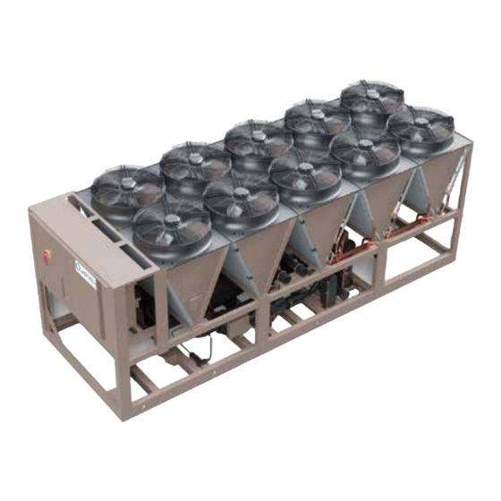
Air-Cooled Screw Liquid Chillers
New Release
Form QTC4-NM2 (523)
Installation, Operation, Maintenance
035-29078-000
Model QTC4 Style B
Air-Cooled Screw Liquid Chillers with Variable Speed Drive
Frame Sizes 016 to 026
150 ton to 550 ton
525 kW to 1,934 kW
2 Compressor
50 Hz and 60 Hz
R-134a or R-513A
Issue Date:
May 12, 2023
Advertisement
Table of Contents

Related Manuals for Quantech QTC40160


Summary of Contents for Quantech QTC40160
- Page 1 Air-Cooled Screw Liquid Chillers New Release Form QTC4-NM2 (523) Installation, Operation, Maintenance 035-29078-000 Model QTC4 Style B Air-Cooled Screw Liquid Chillers with Variable Speed Drive Frame Sizes 016 to 026 150 ton to 550 ton 525 kW to 1,934 kW 2 Compressor 50 Hz and 60 Hz R-134a or R-513A...
- Page 2 Indicates a potentially hazardous situa- Highlights additional information useful tion which will result in possible injuries to the technician in completing the work or damage to equipment if proper care is being performed properly. not taken. Quantech...
- Page 3 Johnson Controls Service office or accessing the John- son Controls Knowledge Exchange website at https:// docs.johnsoncontrols.com/chillers/ Quantech...
- Page 4 Planned Service Agreement that leverages real time and generalized conditions. In lieu of the traditional and historical data, delivering performance reporting, maintenance program, a Johnson Controls Quantech corrective actions required and data enabled guidance Conditioned Based Maintenance (CBM) program can for optimal operation and lifecycle assurance.
- Page 5 Form QTC4-NM2 Issue date: 05/12/2023 Unit nonmenclature UNIT NOMENCLATURE QTC4 SXXX Base Product Type Q = Quantech TC = Variable Speed Screw Level / Refrigerant 4 = Air Cooled Design Series A = Refrigerant R-134a B = Refrigerant R-513A Model Number...
-
Page 6: Table Of Contents
About this manual ............................12 Misuse of equipment ............................12 Section 2 - Product description ...........................15 General system description ..........................15 Semi-hermetic Quantech twin-screw compressors ..................17 Evaporator ..............................17 Condenser ..............................17 Refrigerant circuit ............................17 Electrical ................................. 17 Building automation system capabilities ...................... - Page 7 History key ..............................128 Setpoints key ..............................135 Program key ..............................137 Unit setup mode ............................140 Options key ..............................147 Date/time and schedule keys ........................150 Manual override key ............................. 153 Print key ............................... 154 System switches key ............................ 157 Quantech...
- Page 8 Maintenance requirements for QTC4 chillers ....................175 R-134a conversion table ..........................179 R-513A conversion table, temperature to pressure ..................180 Chilled liquid and suction temperature sensor input voltage ............... 181 Section 10 - Decommissioning, dismantling, and disposal ................185 General ................................. 185 Temperature ..............................186 Quantech...
- Page 9 Figure 1 - QTC4 air-cooled screw liquid chiller with variable speed drive .............. 15 Figure 2 - Chiller control system ..........................16 Figure 3 - View of Quantech control center user interface ..................19 Figure 4 - Lifting lugs ..............................24 Figure 5 - Lifting using lugs.............................24 Figure 6 - Power panel.
- Page 10 Table 39 - Outside air temperature sensor input voltage, measured signal to shield at the sensor ...... 182 Table 40 - Pressure transducer output voltage, measured signal to return at the transducer ......183 Table 41 - Motor temperature sensor resistance ....................184 Table 42 - SI metric conversion ..........................186 Quantech...
-
Page 11: Section 1 - General Chiller Information And Safety
Issue date: 05/12/2023 Section 1 - General chiller information and safety Introduction Warranty Quantech QTC4 chillers are manufactured to the high- Quantech warrants QTC4 chillers in accordance with est design and construction standards to ensure high the Limited Warranty Engineered Systems Equipment performance, reliability and adaptability to all types of procedure. -
Page 12: Quality Assurance And Safety
• ASME Boiler and Pressure Vessel Code, Section This manual and any other document supplied with VIII, Division 1. the unit are the property of Quantech which reserves GB marked units conform to the following standards: all rights. They may not be reproduced, in whole or in part, without written authorization from an authorized •... - Page 13 EN 61000-6-2:2005 and EN 61000-6 working in contact with any components to avoid risk 4:2007 (with EN 55011:2007 limits). It is not intended of minor abrasions and lacerations. to be used on a low-voltage public network which sup- Quantech...
- Page 14 When switching from utility power to generator power, a minimum of a 10 s delay must be provided. This same delay is required when switching power back from generator power to utility power, unless a synchronized transfer system is used. Quantech...
-
Page 15: Section 2 - Product Description
Issue date: 05/12/2023 Section 2 - Product description General system description Quantech QTC4 chillers are designed for water or gly- col cooling. All units are designed to be located outside The QTC4 Chiller combines the best of modern screw on the roof of a building or at ground level. -
Page 16: Figure 2 - Chiller Control System
The basic system control and VSD system compressor speed. Displacement Power Factor is 0. 95 architecture is shown in Figure 2 on page 16. at part or full load. Quantech... -
Page 17: Semi-Hermetic Quantech Twin-Screw Compressors
The QTC4 Style B introduces next-gen 4G microchan- • Orifice and electronic expansion valve. nel coils to the Quantech screw compressor chiller line. • A brazed plate heat exchanger is located in each This design allows for bigger flow channels, reducing refrigerant circuit to increase the system efficiency. -
Page 18: Building Automation System Capabilities
SC-EQUIP Gateway provides an economical and ver- compressor satile connection between Quantech equipment and open/standard protocols. It efficiently manages the • Evaporator pump status communication protocols currently used by Quan- • Evaporator heater status tech equipment, exposing the data in a consistent, or- •... -
Page 19: Accessories And Options
(4 mA to 20 mA or 0 VDC to 10 VDC) from a BAS system. Fan options Figure 3 - View of Quantech control center user Low Sound Fans – The chiller is equipped with spe- interface cially designed fans and motors to provide lower sound levels yet retain appropriate airflow. - Page 20 Option available for front fluid inlet way provides communication between the equipment (control panel end) and back fluid connections for and Building Automation Systems, including BACnet three-pass evaporators. Three-pass evaporators have (MS/TP), Modbus, LON, and N2. inlet and outlet connections on the opposite ends. Quantech...
- Page 21 The circuit breaker is sized to provide motor branch circuit protec- tion, short circuit protection and ground fault protec- tion for the motor branch-circuit conductors, the motor control apparatus and the motors. Quantech...
- Page 22 Form QTC4-NM2 Issue date: 05/12/2023 This page is intentionally left blank. Quantech...
-
Page 23: Section 3 - Rigging, Handling, And Storage
If the unit is to be put into storage, before installation, observe the following precautions: • To prevent inadvertent operation of the pressure relief devices, do not steam clean the unit. • Inspect the unit periodically during storage. Quantech... -
Page 24: Inspecting The Delivery
• Report any major damage immediately to your lo- cal Quantech representative. Moving the chiller Before moving the unit, ensure that the installation site is suitable for installing the unit and is easily capable of supporting the weight of the unit and all associated services. -
Page 25: Figure 6 - Power Panel. 1 To 4
• Lifting instructions are available on a label on the chiller and on the shipping bag. Figure 6 - Unit lifting point locations Table 1 - Unit lifting point locations QTC4 model QTC40160 13.67 347.3 59.7 1516.5 133.42 3389 188.00 4776.0... -
Page 26: Figure 7 - Power Panel, 1 To 5
159.55 4052.5 253.22 6431.9 305.43 7757.9 QTC40265 13.67 347.3 101.5 2578.1 159.55 4052.5 253.22 6431.9 305.43 7757.9 QTC40295 13.67 347.3 101.5 2578.1 159.55 4052.5 253.22 6431.9 349.41 8874.9 QTC40325 13.67 347.3 101.5 2578.1 159.55 4052.5 253.22 6431.9 349.41 8874.9 Quantech... -
Page 27: Figure 8 - Power Panel, 1 To 6
QTC40495 13.67 347.3 101.5 2578.1 159.55 4052.5 253.22 6431.9 305.6 7762.3 455.86 11578.9 QTC40365 13.67 347.3 101.5 2578.1 159.55 4052.5 253.22 6431.9 305.6 7762.3 455.86 11578.9 QTC40395 13.67 347.3 101.5 2578.1 159.55 4052.5 253.22 6431.9 305.6 7762.3 455.86 11578.9 Quantech... -
Page 28: Figure 9 - Power Panel, 1 To 8
13.67 347.3 101.5 2578.1 159.55 4052.5 253.22 6431.9 305.6 7762.3 413.48 10502.3 443.08 11254.2 529.69 13454.2 0450 QTC4 13.67 347.3 101.5 2578.1 159.55 4052.5 253.22 6431.9 305.6 7762.3 413.48 10502.3 443.08 11254.2 529.69 13454.2 0405 QTC4 13.67 347.3 101.5 2578.1 159.55 4052.5 253.22 6431.9 305.6 7762.3 424.36 10778.9 447.02 11354.4 533.63 13554.4 0470 Quantech... -
Page 29: Section 4 - Installation
Space the channels with the same centers as the unit When units are installed in an enclosure, the enclosure side and front base rails. This allow you to fit vibra- height cannot exceed the height of the unit on more tion isolators if required. Isolators are recommended Quantech... -
Page 30: Figure 10 - Acceptable Minimum Clearances Around And Between Units
It is also necessary to consider ac- cess requirements for safe operation and maintenance of the unit and power and control panels. Local health and safety regulations, or practical considerations for service replacement of large compo- nents, may require larger clearances than those recommended. Quantech... -
Page 31: Vibration Isolators
1 in. N.P.T. connection can be obtained from clockwise to lower. Quantech as an accessory for the unit. Alternatively, a 4. Do this two turns at a time until the top plates of differential pressure switch fitted across an orifice plate all mounts are between 1/4 in. -
Page 32: Evaporator Pressure Drop
If there is a potential 88 ft H2O (263 kPa). Follow Chiller FOF for more for power loss, Quantech requires that the evaporator information on water side pressure drop for specific is drained or that water in the chilled water circuit be chiller configurations. -
Page 33: Water Treatment
This increases the can be recirculated to the chiller. thermal mass and flywheel effect within the system (that is, the more; the better) which in turn promotes stable water temperature control and increases reliabil- ity by reducing compressor cycling. Quantech... -
Page 34: Thermal Storage
Variable primary flow Figure 13 - Suggested layout for applications with a flow rate less than the evaporator Quantech recommends a maximum 10% per minute minimum allowable flow rate flow rate of change, based on design flow, for variable In applications where the required flow rate is greater primary flow applications. -
Page 35: Table 3 - Evaporator Connections Dimensions
298.5 0340 DIN200 221.5 298.5 0365 DIN200 221.5 298.5 0395 DIN200 221.5 298.5 0405 DIN200 221.5 298.5 0450 DIN200 221.5 298.5 0470 DIN200 221.5 298.5 0495 DIN200 221.5 298.5 * See Figure 16 on page 36 for flange dimensions. Quantech... -
Page 36: Refrigerant Relief Valve Piping
If these pre- cautions are not followed it could lead to a risk of electrocution. In addition, electrical noise may cause malfunctions or damage the unit and its controls. Quantech... -
Page 37: Power Wiring
In sub- taken using a common point of isolation freezing weather, this could cause serious (not supplied by Quantech). damage to the chiller due to evaporator freeze-up. Do not remove power unless alternate means are taken to ensure op-... -
Page 38: Volts Free Contacts
• Mount the thermal dispersion flow switch on the top of the horizontal pipes only if the pipe is fully filled with liquid. Mount the thermal dispersion flow switch on the bottom of the horizontal pipes only if the pipe is free from buildup. Quantech... -
Page 39: Power Supply Wiring
Consult YorkWorks or the chiller 230/60/3 208–254 data plate for electrical data on a specific 380/60/3 342–418 chiller. 400/60/3 360–440 460/60/3 414–508 575/60/3 520–635 400/50/3 360–440 Figure 18 - Single point power wiring Quantech... -
Page 40: Figure 19 - Dual Point Power Wiring
230/60/3 208–254 ordered. Consult YorkWorks or the chiller 380/60/3 342–418 data plate for electrical data on a specific 400/60/3 360–440 chiller. 460/60/3 414–508 575/60/3 520–635 400/50/3 360–440 Figure 19 - Dual point power wiring Quantech... -
Page 41: Customer Control Wiring
In subfreezing regions, failure to connect EVAP. PUMP START SIGNAL from terminal 23 and ter- minal 24 to chilled water pump starter will void warranty, except when the water in the evaporator is fully dried or appropriate concentration of glycol is reached in the water system. Figure 20 - Customer control connections Quantech... -
Page 42: Thermal Dispersion Flow Switch Connections
Wire color Connection in VSD panel Red/black ITB - 13 Red/yellow ITB - 2 ITB - 2 Terminal No. 11 in relay board No. 1 Red/white (115 VAC) Green Not used Figure 21 - Thermal dispersion flow switch connections Quantech... -
Page 43: Figure 22 - Reserved Customer Wiring Entry
IP65. 220VAC-1PH-50HZ (CUSTOMER CONNECTION) PE/G WBHTR POLE BREAKER 10A 240V 325, PE/G 325A 2, 29, G 324 326, 326A PE/G 325, 326, PE/G ETH1 ETH2 325A, 326A, PE/G LD28285 Figure 23 - Water box heater wiring box Quantech... - Page 44 18-4-AWG. Before turning on the breaker, make sure the evaporator is filled with water. Misop- eration may void the warranty and a water box heater fail, which leads to the freezing of the evaporator. Quantech...
-
Page 45: Table 4 - Standard 2 Hp Condenser Fans, Single Point Electrical Lug Data
#2 – 600 #1 ~ 500 #2 ~ 600 kcmil kcmil kcmil #2 – 600 2/0 ~ 500 #2 – 600 kcmil kcmil kcmil #2 – 600 #1 ~ 500 #2 ~ 600 kcmil kcmil kcmil Quantech... - Page 46 #2 – 600 #1 ~ 500 #2 ~ 600 kcmil kcmil kcmil #2 – 600 2/0 ~ 500 #2 – 600 kcmil kcmil kcmil #2 – 600 #1 ~ 500 #2 ~ 600 kcmil kcmil kcmil Quantech...
- Page 47 #2 – 600 #1 ~ 500 #2 ~ 600 kcmil kcmil kcmil #2 – 600 2/0 ~ 500 #2 – 600 kcmil kcmil kcmil #2 – 600 #1 ~ 500 #2 ~ 600 kcmil kcmil kcmil Quantech...
- Page 48 #2 – 600 #1 ~ 500 #2 ~ 600 kcmil kcmil kcmil #2 – 600 2/0 ~ 500 #2 – 600 kcmil kcmil kcmil #2 – 600 #1 ~ 500 #2 ~ 600 kcmil kcmil kcmil Quantech...
- Page 49 #2 – 600 #1 ~ 500 #2 ~ 600 kcmil kcmil kcmil #2 – 600 2/0 ~ 500 #2 – 600 kcmil kcmil kcmil #2 – 600 #1 ~ 500 #2 ~ 600 kcmil kcmil kcmil Quantech...
- Page 50 #2 – 600 4/0 ~ 500 #2 ~ 600 kcmil kcmil kcmil #2 – 600 3/0 ~ 400 #2 ~ 600 kcmil kcmil kcmil #2 – 600 3/0 ~ 400 #2 ~ 600 kcmil kcmil kcmil Quantech...
- Page 51 #2 – 600 4/0 - 500 #2 ~ 600 kcmil kcmil kcmil #2 – 600 3/0 - 400 #2 ~ 600 kcmil kcmil kcmil #2 – 600 3/0 - 400 #2 ~ 600 kcmil kcmil kcmil Quantech...
- Page 52 #2 – 600 4/0 - 500 #2 ~ 600 kcmil kcmil kcmil 0405 2205/2605 #2 – 600 40 - 500 #2 ~ 600 kcmil kcmil kcmil 0470 2605 #2 – 600 4/0 - 500 #2 ~ 600 kcmil kcmil kcmil Quantech...
-
Page 53: Table 5 - Standard 2 Hp Condenser Fans, Dual Point Electrical Lug Data
#2 – 600 3/0 - 3/0 - kcmil 400kcmil 400kcmil #2 – 600 3/0 - 3/0 - kcmil 400kcmil 400kcmil #2 – 600 #1 - #1 - kcmil 500kcmil 500kcmil #2 – 600 #1 - #1 - kcmil 500kcmil 500kcmil Quantech... - Page 54 #2 – 600 3/0 - 3/0 - kcmil 400kcmil 400kcmil #2 – 600 3/0 - 3/0 - kcmil 400kcmil 400kcmil #2 – 600 #1 - #1 - kcmil 500kcmil 500kcmil #2 – 600 #1 - #1 - kcmil 500kcmil 500kcmil Quantech...
-
Page 55: Table 6 - Ebm Condenser Fans, Single Point Electrical Lug Data
#2 – 600 3/0 ~ 400 #2 ~ 600 kcmil kcmil kcmil #2 – 600 3/0 ~ 400 #2 ~ 600 kcmil kcmil kcmil #2 – 600 #1 ~ 500 #2 ~ 600 kcmil kcmil kcmil Quantech... - Page 56 #2 – 600 3/0 ~ 400 #2 ~ 600 kcmil kcmil kcmil #2 – 600 #1 ~ 500 #2 ~ 600 kcmil kcmil kcmil #2 – 600 #1 ~ 500 #2 ~ 600 kcmil kcmil kcmil Quantech...
- Page 57 #2 – 600 3/0 ~ 400 #2 ~ 600 kcmil kcmil kcmil #2 – 600 #1 – 500 #2 ~ 600 kcmil kcmil kcmil #2 – 600 #1 – 500 #2 ~ 600 kcmil kcmil kcmil Quantech...
- Page 58 #2 – 600 3/0 ~ 400 #2 ~ 600 kcmil kcmil kcmil #2 – 600 #1 ~ 500 #2 ~ 600 kcmil kcmil kcmil #2 – 600 #1 ~ 500 #2 ~ 600 kcmil kcmil kcmil Quantech...
- Page 59 #2 – 600 3/0 ~ 400 #2 ~ 600 kcmil kcmil kcmil #2 – 600 #1 ~ 500 #2 ~ 600 kcmil kcmil kcmil #2 – 600 #1 ~ 500 #2 ~ 600 kcmil kcmil kcmil Quantech...
- Page 60 #2 – 600 4/0 ~ 500 #2 ~ 600 kcmil kcmil kcmil #2 – 600 4/0 ~ 500 #2 ~ 600 kcmil kcmil kcmil #2 – 600 3/0 ~ 400 #2 ~ 600 kcmil kcmil kcmil Quantech...
- Page 61 #2 – 600 4/0 ~ 500 #2 ~ 600 kcmil kcmil kcmil #2 – 600 4/0 ~ 500 #2 ~ 600 kcmil kcmil kcmil #2 – 600 3/0 ~ 400 #2 ~ 600 kcmil kcmil kcmil Quantech...
- Page 62 #2 – 600 4/0 ~ 500 4/0 ~ 500 kcmil kcmil kcmil #2 – 600 4/0 ~ 500 4/0 ~ 500 kcmil kcmil kcmil #2 – 600 4/0 ~ 500 2/0 ~ 500 kcmil kcmil kcmil Quantech...
-
Page 63: Table 7 - Ebm Condenser Fans, Dual Point Electrical Lug Data
3/0 ~ 400 #2 – 600 3/0 ~ 400 kcmil kcmil kcmil 3/0 ~ 400 #2 – 600 3/0 ~ 400 kcmil kcmil kcmil #2 – 600 #1 ~ 500 #1 ~ 500 kcmil kcmil kcmil Quantech... - Page 64 3/0 ~ 400 kcmil kcmil kcmil #2 – 600 3/0 ~ 3/0 ~ 400 kcmil kcmil kcmil #2 – 600 3/0 ~ 3/0 ~ 400 kcmil kcmil kcmil #2 – 600 #1 ~ 500 #1 ~ 500 kcmil kcmil kcmil Quantech...
-
Page 65: Section 5 - Technical Data
Issue date: 05/12/2023 Section 5 - Technical data The data shown in the tables of this section are appli- Contact your nearest Quantech sales representative for cable to selected standard configurations. Other con- the chiller configuration that best matches your spe- figurations are available through the configuration and cific needs. -
Page 66: Table 8 - Physical Data, Microchannel Coil
(19) Notes: 1. Shipping and operating weights shown are for base unit; selected options may add weight to unit. Contact your nearest Quantech sales representative for weight data. 2. For leaving liquid temperature below 40°F (4.4°C) or above 70°F (21.1°C), contact your nearest Quantech sales representative for applica- tion requirements. - Page 67 (19) Notes: 1. Shipping and operating weights shown are for base unit; selected options may add weight to unit. Contact your nearest Quantech sales representative for weight data. 2. For leaving liquid temperature below 40°F (4.4°C) or above 70°F (21.1°C), contact your nearest Quantech sales representative for applica- tion requirements.
- Page 68 (mm) Notes: 1. Shipping and operating weights shown are for base unit; selected options may add weight to unit. Contact your nearest Quantech sales representative for weight data. 2. For leaving liquid temperature below 40°F (4.4°C) or above 70°F (21.1°C), contact your nearest Quantech sales representative for applica- tion requirements.
- Page 69 (19) Notes: 1. Shipping and operating weights shown are for base unit; selected options may add weight to unit. Contact your nearest Quantech sales representative for weight data. 2. For leaving liquid temperature below 40°F (4.4°C) or above 70°F (21.1°C), contact your nearest Quantech sales representative for applica- tion requirements.
-
Page 70: Figure 24 - Standard Two-Pass, Right Side Inlet/Outlet Evaporator Connections
Note: Minimum chilled water flow rate is for full load selections; variable primary flow ratings as low as 50% of the minimum are permitted. Glycol limits are higher. Contact your Quantech sales representative for ratings and further information. Quantech... - Page 71 Note: Minimum chilled water flow rate is for full load selections; variable primary flow ratings as low as 50% of the minimum are permitted. Glycol limits are higher. Contact your Quantech sales representative for ratings and further information. Quantech...
-
Page 72: Figure 25 - Optional Two-Pass Left Side Inlet/Outlet Connections
Note: Minimum chilled water flow rate is for full load selections; variable primary flow ratings as low as 50% of the minimum are permitted. Glycol limits are higher. Contact your Quantech sales representative for ratings and further information. Quantech... - Page 73 Note: Minimum chilled water flow rate is for full load selections; variable primary flow ratings as low as 50% of the minimum are permitted. Glycol limits are higher. Contact your Quantech sales representative for ratings and further information. Quantech...
-
Page 74: Figure 26 - Standard Two-Pass Left Side Inlet/Outlet Connections
Note: Minimum chilled water flow rate is for full load selections; variable primary flow ratings as low as 50% of the minimum are permitted. Glycol limits are higher. Contact your Quantech sales representative for ratings and further information. Quantech... -
Page 75: Figure 27 - Optional Three-Pass Inlet/Outlet Connections
Note: Minimum chilled water flow rate is for full load selections; variable primary flow ratings as low as 50% of the minimum are permitted. Glycol limits are higher. Contact your Quantech sales representative for ratings and further information. Quantech... - Page 76 Note: Minimum chilled water flow rate is for full load selections; variable primary flow ratings as low as 50% of the minimum are permitted. Glycol limits are higher. Contact your Quantech sales representative for ratings and further information. Quantech...
-
Page 77: Figure 28 - Qtc4 Dimensions
Section 5 - Technical data Issue date: 05/12/2023 The following data is applicable to select configura- Contact your nearest Quantech sales representative for tions. Other configurations are available through the the chiller configuration that best matches your spe- configuration/selection software. -
Page 78: Figure 29 - Isolator Selection And Mounting Locations
– – – – – – – – – – – – – – Notes: • Contact your nearest Quantech sales representative for weight data. • All isolator mounting holes are 19 mm. • Dimensions are in inches (mm). Quantech... -
Page 79: Figure 30 - Isolator Selection And Mounting Locations
– – – – – – – – – – – – – – Notes: • Contact your nearest Quantech sales representative for weight data. • All isolator mounting holes are 19 mm. • Dimensions are in inches (mm). Quantech... -
Page 80: Figure 31 - Isolator Selection And Mounting Locations
– – – – – – – – – – – – – – Notes: • Contact your nearest Quantech sales representative for weight data. • All isolator mounting holes are 19 mm. • Dimensions are in inches (mm). Quantech... -
Page 81: Figure 32 - Isolator Selection And Mounting Locations
– – – – – – – – – – – – – – Notes: • Contact your nearest Quantech sales representative for weight data. • All isolator mounting holes are 19 mm. • Dimensions are in inches (mm). Quantech... -
Page 82: Figure 33 - Isolator Selection And Mounting Locations
– – – – – – – – – – – – – – Notes: • Contact your nearest Quantech sales representative for weight data. • All isolator mounting holes are 19 mm. • Dimensions are in inches (mm). Quantech... -
Page 83: Figure 34 - Isolator Selection And Mounting Locations
– – – – – – – – – – – – – – Notes: • Contact your nearest Quantech sales representative for weight data. • All isolator mounting holes are 19 mm. • Dimensions are in inches (mm). Quantech... -
Page 84: Figure 35 - Isolator Selection And Mounting Locations
– – – – – – – – – – – – – – Notes: • Contact your nearest Quantech sales representative for weight data. • All isolator mounting holes are 19 mm. • Dimensions are in inches (mm). Quantech... -
Page 85: Figure 36 - Isolator Selection And Mounting Locations
– – – – – – – – – – – – – – Notes: • Contact your nearest Quantech sales representative for weight data. • All isolator mounting holes are 19 mm. • Dimensions are in inches (mm). Quantech... -
Page 86: Figure 37 - Isolator Selection And Mounting Locations
– – 540.2 540.2 503.5 (13,721) (13,721) (12,789) – – – – 585.1 (14,861) Notes: • Contact your nearest Quantech sales representative for weight data. • All isolator mounting holes are 19 mm. • Dimensions are in inches (mm). Quantech... -
Page 87: Figure 38 - Isolator Selection And Mounting Locations
(10,721) (10,712) – – – – 503.5 (12,789) – – – – 585.1 (14,861) Notes: • Contact your nearest Quantech sales representative for weight data. • All isolator mounting holes are 19 mm. • Dimensions are in inches (mm). Quantech... -
Page 88: Elastomeric Isolator Installation
Install the isola- tor base (A) on a level surface. Shim or grout as required, leveling all isolator bases to the same el- evation. 0.03125 of an inch maximum difference can be tolerated. Quantech... -
Page 89: Elastomeric Isolator Specifications
(M27 X 3) (76.20) Type B 029-25335-004 (434005) Table 15 - Elastomeric weights Model P/N Isolator color Weight range 029-25335-001 Charcoal Up to 825 Up to 374 (434002) 029-25335-002 Brick red 826–1688 375–766 (434004) 029-25335-004 Charcoal 1689–4000 767–1814 (434005) Quantech... -
Page 90: One Inch Deflection Isolator Installation
0.25 in. clearance is achieved between the (0.25 in. maximum difference can be tolerated). lower housing and upper housing. See previous figure. 3. Bolt or anchor all isolators to supporting structure using base slotted holes (C). 8. Fine adjust isolators to level equipment. Quantech... -
Page 91: One Inch Deflection Spring Isolator Specifications
Use either all CP's or all CP2's at all locations on a unit. • Installation requires bolting or anchoring mount to support structure with a 2 x 0.625 in. diameter bolts or 2 x 0.5 in. diameter concrete anchors. • All springs are designed for 50% over-travel. Quantech... -
Page 92: Two Inch Deflection, Isolator Installation And Adjustment
0.25 in. to 0.375 in. gap. The limit top of plate (A) of isolator. stop nuts must be kept at this gap to ensure uni- form bolt loading during uplift, as is the case when the equipment is drained. Quantech... -
Page 93: Two Inch Deflection, Restrained Spring Isolator Specifications
All dimensions are in inches, interpret as per ANSI Y14. • Equipment must be bolted or welded to the top plate to meet allowable seismic ratings. • All springs are designed for 50% overload capacity with exception of the 029-25336-013 and 029-25336-014. • Consult Quantech for concrete installation. Quantech... - Page 94 Form QTC4-NM2 Issue date: 05/12/2023 This page is intentionally left blank. Quantech...
-
Page 95: Section 6 - Commissioning
Compressor oil refrigerant pressure is present in both systems and To add oil to a circuit - connect a Quantech hand oil that no leaks are apparent. If no pressure is present, pump (Part No. 470-10654-000) to the 1/4 in. (6.35... -
Page 96: Figure 45 - Led Indicator Buttons
Purge air from the top of the LD29413 evaporator using the plugged air vent mounted on the Figure 45 - LED indicator buttons top of the evaporator body. Quantech... -
Page 97: Figure 46 - Flow Switch Set
When the normal flow exceeds the representation maximum reset required must be programmed by range of the display, the LED displays the following: pressing the SETPOINTS key. See Setpoints key on Page 135. HIGH LD29416 Figure 48 - Flow exceeds the representation range Quantech... -
Page 98: First Time Startup
If a high heat load is present, the control- of the following freeze protection protocols must be ler will increase the speed of the compressors. followed: Quantech... -
Page 99: Table 19 - Qtc4 Freeze Damage Protection Requirements
Required if chilled fluid pumps Not required from 32⁰F (0⁰C) down to 0⁰F service isolation valve is not are not controlled by chiller con- (-17.8⁰C) selected trol panel Ambient air temperatures Required Required Required below 0⁰F (-17.8⁰C) down to -20⁰F (-28⁰C) Quantech... - Page 100 Form QTC4-NM2 Issue date: 05/12/2023 This page is intentionally left blank. Quantech...
-
Page 101: Section 7 - Operation
▲,▼,◄, and ► play message displayed under the data (UNIT DATA, (ARROW) keys. The keypad uses an overlay to con- SYSTEM DATA, and so on) keys. Quantech... - Page 102 30 s or if pear for 2 s indicating the user must choose between the pump has run in the last 30 s to prevent pump motor accepting or canceling the change: overheating. Quantech...
- Page 103 OFF (dry contact open) to indicate an alarm of power failure. situation. The Alarm will be activated (contacts open), if any of the following are true. Run permissive A Run permissive input is available for each system. Quantech...
-
Page 104: Basic Operating Sequence
24 VAC power is applied to the 331-03478-xxx microboard connector J12 and is then used to create the various DC power sources required by the microboard circuitry. If the chiller control is malfunctioning, measure the power supply test points to determine the status of the microboard. Quantech... - Page 105 JP6 Remote Sound Limit jumper position (Pins 1 to 2 TP5 +15 V [11.3 VDC to 16.6 VDC] powers the analog (left) = 4mA to 20 mA, Pins 2 to 3 (right) = 0 VDC to outputs to the EEV valves. 10 VDC. Quantech...
-
Page 106: Figure 50 - New 331-03478-Xxx Microboard
JP4, JP5, JP6 Port 2 RS485 U18 VSD Remote Setpoint TP5 + 15 V Datalog RS-485 Driver Jumpers U23 Port 2 U26 PORT 1 U5 RTC/BRAM TP10 + 24 V RS-485 Driver RS-485 Driver Figure 50 - New 331-03478-xxx microboard Quantech... -
Page 107: Sc-Eq Communications Card
BAS SC-EQ points list on the Chillers SOFTWARE UPDATE IN PROGRESS PLEASE Knowledge Exchange. For more informa- WAIT tion, contact your local Quantech sales representative. The keypad and display do not respond during the flash update. After the software update is com- J2 VSD#1 and J1 VSD#2 connections headers for plete, the controller automatically reboots. -
Page 108: Data Logging
20150303.csv file into Excel and look at the system parameter details leading up to the 2:05pm event. If there are other internal errors that occur, the panel Follow all Quantech Safety Directives displays the following message until the user presses when inserting or removing the SD card the enter key. -
Page 109: Unit Warning
• After initializing the VSD. the ENTER key. • If no number-of-compressors-select jumpers are Again, follow the Quantech Safety Directives to stop installed. the chiller, power off the unit and open the control cab- • If more than 1 jumper is installed. -
Page 110: Unit Safeties
1.1°C (2°F). fault message will show a YYYYYYY to indicate that a system is in a FAULT condition and will restart when the fault clears or LOCKOUT” and will not restart until the operator clears the fault using the keypad. Quantech... -
Page 111: System Safeties, Faults
VSD fault occurred the VSD for a data request. The following is an ex- (that is, IGBT Gate Drive, Single Phase Input, VSD CT ample of a Comms Failure fault message: Plug, and so on). The control panel fault that occurred Quantech... - Page 112 120 s anti-recycle timer times out or LOCK- usually indicating that a compressor is not running. This OUT and will not restart until the operator clears the safety is ignored for the first 10 s of operation. fault using the keypad. Quantech...
-
Page 113: Table 21 - Low Differential Oil Pressure Cutout
The X indicates the system and YYYYYYY indicates the system is in a FAULT condition and will restart when the 120 s anti-recycle timer times out or LOCK- OUT and will not restart until the operator clears the fault using the keypad. Quantech... -
Page 114: Table 22 - Discharge Pressure Load Limiting/Unloading
Discharge pressure cutout - 6 psig 6 Hz Discharge pressure cutout - 4.5 psig 7 Hz Discharge pressure cutout - 3 psig 8 Hz Discharge pressure cutout - 1.5 psig 9 Hz Discharge Pressure Cutout - 0 psig 10 Hz Quantech... -
Page 115: Table 24 - Start Inhibit Sensor Thresholds
The safety will not cause a lockout and the system fault A specific motor temperature sensor can be ig- will reset when power is returned. The following is a nored using the unit setup mode, if it fails. Report sample message: any failure to Quantech service for investigation. Quantech... - Page 116 The fault occurs when the SYS X YYYYYYYYYY Differential Oil to Discharge Pressure is greater than ISO VALVE FAILED TO OPEN 50 psid. Following is the system message, where X is the sys- tem number: SYS X WARNING REPLACE OIL FILTER Quantech...
-
Page 117: Section 8 - Micropanel
MANUAL OVERRIDE mode. This message is a pri- priate general status message: ority message and cannot be overridden by any other (C)2004 QUANTECH INTERNATIONAL CORPORATION STATUS message. When in Manual Override, no other status message will ever be present. C.XXX.XX.XX 18-SEPT-2010 12:45: AM... - Page 118 The motor current limiting message indicates the mo- micro has not loaded the lead system far enough into tor current load limit or motor current unloading is in the loading sequence to bring the lag system ON. This effect. Quantech...
- Page 119 The setpoint may be offset the VSD Baseplate temp is high and load limit or un- using a remote voltage or current signal. The sound loading is in effect. limit option must be activated for this function to operate. Quantech...
-
Page 120: Unit Data Key
The next key press displays the error in temperature tive will be displayed, while the inactive items will be between the actual leaving chilled liquid temperature blanked out. and the setpoint temperature. The display also shows the rate of change of the chilled liquid temperature. Quantech... - Page 121 The chiller is in remote mode. • BAS - SC-EQ using Remote BAS connection. The chiller in remote mode. • CURR - Remote Current Limiting is enabled. • TEMP - Remote Temperature Reset is enabled. • SOUND - Remote Sound Limiting is enabled. Quantech...
-
Page 122: System Data Keys 1 Through 4
▼ (DOWN ARROW) key displays system suction thermistor temperatures. and condenser liquid pressure. SYS 1 MOTOR TEMPS T1 = XXX.X °F SYS 1 PRESSURES SUCTION = XXXX PSIG T2 = XXX.X °F T3 = XXX.X °F CONDENSER LIQUID = XXXX PSIG Quantech... - Page 123 • 2 = MANUAL • 3 = INACTIVE • 4 = START HOLD • 5 = SETP HOLD • 6 = PID CTRL • 9 = OS DIFF OR • 10 = DS DIFF OR • 20 = VSD COOL Quantech...
-
Page 124: Table 25 - System Sensor Minimum And Maximum Outputs
Remote current limit 100% 0 mA to 20 mA or 2 VDC to 10 VDC 4 mA to 20 mA, 0 VDC to 10 VDC, Remote sound limit 100% 0 mA to 20 mA or 2 VDC to 10 VDC Quantech... -
Page 125: Vsd Data Key
“XXX” instead of a numeric value. unless the circuit board is replaced. VSD CURRENT LIMIT LOCAL = XXX %FLA COMP 1 MOTOR OVERLOAD = XXX AMPS ISN = XXX REMOTE = XXX %FLA COMP 2 MOTOR OVERLOAD = XXX AMPS Quantech... -
Page 126: Table 26 - Compressor Overload Settings
400 V - 50 Hz 460 V - 60 Hz (see note 1) 50/60 Hz tons Sys # 1 Sys # 2 Sys # 1 Sys # 2 Sys # 1 Sys # 2 QTC40160 QTC40200 QTC40170 QTC40210 QTC40190 QTC40175 QTC40180 QTC40215 QTC40225... -
Page 127: Operating Hours/Start Counter Key
A single display is available under this key and is dis- displayed with a single key press. The maximum value played as follows. for both hours and starts is 99,999, at which point they HOURS 1=XXXXX, 2=XXXXX will roll over to 0. START 1=XXXXX, 2=XXXXX Quantech... -
Page 128: History Key
If the FAULT SHUTDOWNS history is selected, the Normal shutdowns history following screen is displayed: If the NORMAL SHUTDOWNS history is selected, the following screen is displayed: FAULT HIST XX 18-JUN-2004 10:34:58 AM YYYYYYYYYYYYYYYYYYYYYYYYYYYYYYYYYYYYY NORM HIST XX 18-JUN-2004 10:34:58 AM YYYYYYYYYYYYYYYYYYYYYYYYYYYYYYYYYYYYY Quantech... - Page 129 This message indicates the type of system fault. This screen is skipped if a UNIT Fault caused the shutdown. Ambient air temperature UNIT OUTSIDE AMBIENT AIR TEMP = XXX.X °F This message indicates the ambient air temperature at the time of the fault. Quantech...
- Page 130 This message displays the IGBT highest baseplate limited. temperature for 2 and 3 compressor units at the time of the fault. 4 compressor units display temperatures for 1/3 (T1) and 2/4 (T2). Quantech...
- Page 131 ON or OFF at the time of the fault. SYS 1 DISCHARGE TEMP = XXX.X °F SUPERHEAT = XXX.X SAT TEMP = XXX.X °F This message displays the system discharge, discharge superheat and saturated discharge temperatures at the time of the fault. Quantech...
- Page 132 Imperial units (°F, psig) was selected at the time of the Remote setpoint and range fault. SETPOINTS REMOTE SETPOINT = XXX.X °F REMOTE CONTROL RANGE = +/- X.X °F This message displays the remote setpoint and control range at the time of the fault. Quantech...
- Page 133 If the option is not factory enabled, the option will not Condenser subcooling setpoint appear. PROGRAM SUBCOOLING SETPOINT = XXX.X °F This message indicates the liquid subcooling setpoint programmed at the time of the fault. Quantech...
- Page 134 If the option is not factory activated, the display will not appear. Eductor differential temperature PROGRAM ◄DEF XXXXX LO XXXXX HI XXXXX EDUCTOR DIFFERENTIAL = XXX °F This message indicates the programmed eductor dif- ferential temperature at the time of the fault. Quantech...
-
Page 135: Setpoints Key
The (ENTER) key must also be pressed after the last key a third time displays the remote setpoint and cool- value in the display to store the data into memory. ing range. This display automatically updates about ev- ery 2 s. The following is the remote setpoint message: Quantech... -
Page 136: Table 27 - Setpoint Limits
Water cooling 4.4°C 15.6°C 6.7°C Leaving chilled liquid setpoint 15.0°F 70.0°F 44.0°F Glycol cooling -9.4°C 15.6°C 6.7°C 1.5°F 2.5°F 2.0°F Leaving chilled liquid control range – 0.8°C 1.4°C 1.1°C 2°F 40°F 20°F Maximum remote temperature reset – 1°C 22°C 11°C Quantech... -
Page 137: Program Key
PRESS ENTER KEY TO CONTINUE 2.80 barg (7.7 psig and 40.7 psig) in the Glycol Cool- ing mode. The default value for both modes will be To display the first programmable selection, press the 1.93 barg (28.0 psig). (ENTER) key again. Quantech... - Page 138 = XXX MIN from 0°C to 10.0°C (0°F to 50.0°F). The default value The pulldown current limit time is programmable. is 5.0°F. This allows the microprocessor to limit a system on pulldown limiting for a defined period of time for the Quantech...
-
Page 139: Table 28 - Programmable Operating Parameters
– Sound limit Sound limit setpoint 100% option enabled 5.0°F 50.0°F 15.0°F Eductor temperature differential – 2.77°C 27.8°C 8.3°C Eductor safety time – 10 min 1000 min 30 min* 150.0°F 250.0°F 240.0°F Motor temperature unload – 65.6°C 121.1°C 115.5°C Quantech... -
Page 140: Unit Setup Mode
System 1 compressor CTS24 = 62, CTS36 = 82 – displacement CTS45 = 100, CTS51 = 128, CTS70 = 187, GTS75 = 217 System 2 compressor Same as Sys. 1 – displacement Maximum compressor 121.0 Hz 210.0 Hz 180.0 Hz speed Quantech... - Page 141 Microchannel or round tube Microchannel disabled System 1 evaporator 20.0% 80.0% 50.0% level control setpoint System 2 evaporator 20.0% 80.0% 50.0% level control setpoint Evaporator level control valve startup position Evaporator level 0 min 10 min 3 min control startup delay Quantech...
- Page 142 – 20 Hz speed - 20 Hz Discharge pressure 10 psi/s 99 psi/s 99 psi/s rate threshold Harmonic filter Disabled/enabled Disabled Opt. fan low oil hold 15.0 psid 30.0 psid 15.0 psid diff. Evap. anti-freeze pump Any Disabled/enabled Disabled Quantech...
- Page 143 SETUP MODE CLEAR HISTORY BUFFERS? SETUP MODE CONDENSER FAN CONTROL ◄ ► XXXXXXXXXXXXXXXXXXXXXXXXXXXX ◄ ► XXXXXXXXXXXXXXXXXXXXXXXXXXXX The following three setup OPTION displays are select- able as ENABLED or DISABLED using the ◄ and ► keys according to the options installed on the chiller: Quantech...
- Page 144 • TEMP SENSOR 1 SETUP MODE ◄ DEF XXXXX LO XXXX HI XXXX • TEMP SENSOR 2 FAN POWER EXPNENT = X.X • TEMP SENSOR 3 SETUP MODE ◄ DEF XXXXX LO XXXX HI XXXX DESIGN ELEVATION = XXXXX FT Quantech...
- Page 145 SETUP MODE ◄DEF XXXXX LO XXXXX HI XXXXX ◄ ► XXXXXXXXXXXXXXXXXXXXXXXXXXXX DATA LOGGING TIME = XX SEC SETUP MODE EVAP ANTI-FREEZE PUMP SETUP MODE ◄DEF XXXXX LO XXXXX HI XXXXX ◄ ► XXXXXXXXXXXXXXXXXXXXXXXXXXXX ANTI RECYCLE TIMER = XXX SECS Quantech...
- Page 146 REPLACE OIL FILTER WARNING ◄ ► XXXXXXXXXXXXXXXXXXXXXXXXXXXX The following setup option display is used to select the correct chiller protocol for data communications with the E-link or SC-EQ communication cards: • YORKTalk 3 SETUP MODE YORKTALK PROTOCOL TYPE ◄ ► XXXXXXXXXXXXXXXXXXXXXXXXXXXX Quantech...
-
Page 147: Options Key
Polish, Hungarian, German, French, Portuguese, such as an BAS controller. and Spanish. OPTIONS LOCAL / REMOTE CONTROL MODE OPTIONS DISPLAY LANGUAGE ◄ ► REMOTE CONTROL ◄ ► XXXXXXXXXXXXXXXXXX The default mode is LOCAL CONTROL. The default language is English. Quantech... - Page 148 LEAD / LAG CONTROL MODE ◄ ► 0.0 TO 10.0 VOLTS DC ◄ ► MANUAL SYS 2 LEAD OPTIONS REMOTE CURRENT LIMIT INPUT ◄ ► 2.0 TO 10 VOLTS DC OPTIONS REMOTE CURRENT LIMIT INPUT ◄ ► 0.0 TO 20.0 MILLIAMPS Quantech...
- Page 149 OPTIONS REMOTE SOUND LIMIT INPUT ◄ ► 4.0 TO 20.0 MILLIAMPS The default setting for remote sound limit is DISABLED. This display will only appear if the re- mote sound limit option is enabled under the unit setup mode. Quantech...
-
Page 150: Date/Time And Schedule Keys
◄ or ► (LEFT OR RIGHT ARROW) key to select the day. After the day is CLOCK FRI 18-JUN-2011 10:15:33 AM MONTH ◄ ► = XXX selected, the (ENTER) key must be pressed to store the data. Quantech... - Page 151 AM/PM can be selected by pressing the ◄ or ► correct values for the START hour and minute, press (ARROW) keys. After the meridian is selected, the the (ENTER) key. The cursor will then move to the (ENTER) key must be pressed to store the data. Quantech...
- Page 152 The Holiday schedule must be programmed weekly. If key will scroll backwards to the previous screen. there is no holiday, the “*” key is also used to delete the “*”. The (ENTER) key is used to accept the holiday schedule for the entire week. Quantech...
-
Page 153: Manual Override Key
Remote Contacts, ride mode automatically disables itself after 30 min. UNIT switch and SYSTEM switches permitting. This is a priority message and cannot be overridden by anti- MANUAL OVERRIDE recycle messages, fault messages, and so on, when in Quantech... -
Page 154: Print Key
◄ (LEFT ARROW) or ► History buffer 6 (RIGHT ARROW) keys until the preferred printout is History buffer 7 displayed. History buffer 8 History buffer 9 History buffer 10 Cancel printing The specific printout is initiated by pressing the (ENTER) key. Quantech... - Page 155 UNIT ID NUMBER SOUND LIMIT SETPOINT 100% MOTOR TMP XXX.XXXX.XXXX.XDEGF COMPRESSOR SPEED XXX.X % (if Sound Limiting enabled) COND DRAIN % OPEN XXX.X % UNIT DATA ECONOMIZER % OPEN XXX.X % LEAVING LIQUID TEMP 49.0 DEGF CONDENSER FANS ON Quantech...
- Page 156 ECONOMIZER % OPEN XXX.X% the header information shown as follows: CONDENSER FANS ON Quantech INTERNATIONAL CORPORATION CONDENSER FAN SPEED XXX% (vsd) COMPRESSOR HEATER QTC4 SCREW CHILLER VI STEP SOLENOID 1...
-
Page 157: System Switches Key
(System 1 and 2). sors. SYSTEM SWITCHES SYS 2 ON / OFF / RESET ◄ ► =XXXXXXXXXXXXXX The ◄ (LEFT ARROW) or ► (RIGHT ARROW) keys allow scrolling through the choices of: • SYSTEM OFF (default) • SYSTEM ON • RESET (LOCKOUT) Quantech... - Page 158 Form QTC4-NM2 Issue date: 05/12/2023 This page is intentionally left blank. Quantech...
-
Page 159: Section 9 - Maintenance
Do not run with oil levels above the ter into a maintenance agreement with a Quantech ser- sight glass. Be careful when viewing the sight glass not vice organization to protect the operation of the unit. -
Page 160: Checking The System For Leaks
The acceptable limit for Callout Component Callout Component Compressor discharge line isolation ball valve Condenser drain liquid service valve Liquid line angle valve Suction service valve (Optional) Figure 64 - Service connections Quantech... -
Page 161: System Pressure Test
6. Use the soap solution to test around each unit fit- to either of the following leak detection methods: ting joint and weld seams carefully and thorough- Conducting the soap visual gas leak test or Con- ducting the optional trace gas leak test. Quantech... -
Page 162: Conducting The Optional Trace Gas Leak Test
100 psig (690 kPa). Pressure can be test gas as applicable, make the necessary repairs, increased upto 150 psig to detect very small leaks. repeat the leak tests, evacuate the chiller, and per- form the time-based pressure hold test. Quantech... -
Page 163: System Evacuation
The Figure 66 - Evacuation of the chiller operation Quantech... -
Page 164: Dehydration
If the system reacts much as a refrigerant would. How- system has been pressure tested and found to be tight ever, the vacuum pressure in the system cannot Quantech... -
Page 165: Conducting The Dehydration Process
During the primary or dehydration evacuation, close- there is a leak, in most cases this can be traced to ly monitor the vacuum level. Do not let it fall below an elastomeric or O-ring sealing issue. 5,000 μm or the equivalent 35°F (1.6°C). Quantech... -
Page 166: Conducting The Final Evacuation
See see Figure 66 on page 163 for values. 7. An acceptable vacuum pressure rise is 150 μm in 60 min. Quantech... -
Page 167: Table 32 - R-134A Pressure To Saturated Temperature Conversion
385.0 (26.54) 179.9 (82.2) 120.0 (8.27) 98.0 (36.7) 255.0 (17.58) 147.7 (64.3) 390.0 (26.89) 180.9 (82.7) 125.0 (8.62) 100.4 (38.0) 260.0 (17.93) 149.2 (65.1) 395.0 (27.23) 182.0 (83.3) 130.0 (8.96) 102.7 (39.3) 265.0 (18.27) 150.6 (65.9) 400.0 (27.58) 183.0 (83.9) Quantech... -
Page 168: Table 33 - R-513A Pressure To Saturated Temperature Conversion
Fit this charging connection being transferred to the chiller. between the system charging valve and the fitting on the charging drum. Quantech... -
Page 169: Removing The Refrigerant Charge For Service
Monitor the weight of the recovery Weight – Tare Weight cylinder to determine when the cylinder is full. While handling refrigerant into or out of any chiller, Change the cylinder as needed. every precaution must be taken to prevent air from Quantech... -
Page 170: Checking And Trimming The Refrigerant Charge
Checking the refrigerant charge during unit shutdown Because QTC4 uses a hybrid falling film technology, there are no reliable means to evaluate the refrigerant charge when the chiller is not running. Quantech... -
Page 171: Microchannel Coil Cleaning
Only use cleaning solutions approved by 10 mins. Quantech. The required cleaning procedure is different depend- 4. Repeat the water rinse as described in Step 2 to ing on the type of coil and protective coating supplied remove the cleaning solution. -
Page 172: Cleaning Procedure For Environment Guard Premium Microchannel Coils
Allow the cleaning solution to remain on each of the coils for approximately 10 mins. 4. Repeat the water rinse as described in Step 2 to remove the cleaning solution. Quantech... -
Page 173: Steps To Touch-Up End, Dead Tubes Or Condenser Coil Headers
30 min. Power mixing is pre- erating data. ferred. If needed, make more amount of solution for application. 7. Using the paint brush, apply the touch up paint to the end tubes or coil headers as needed. Quantech... - Page 174 Winterization If glycol is used in the evaporator, the glycol concentration must ensure that the freeze point is below the lowest expected ambient temperature at the chiller loca- tion to avoid evaporator damage. Quantech...
-
Page 175: Maintenance Requirements For Qtc4 Chillers
*** Chiller controller cannot detect the failure of heaters, all heaters including compressor and evaporator heater need to be checked weekly and maintained to be operational in subfreezing regions in winter. Weekly maintenance to heaters and with the chilled water pump controlled by unit controller is recommended and mandatory. Quantech... -
Page 176: Table 35 - Troubleshooting Guide
Check Sensor for intermittent operation Check Wiring for shorts or opens Check respective system fuse 20FU System fault: or 21FU System fuse is blown Control voltage Note: Always remove power to the chiller and ensure the DC Bus voltage has bled off. Quantech... - Page 177 Economizer feed valve malfunction Check economizer feed valve operation Economizer line solenoid purge valve Check economizer line solenoid purge malfunction valve operation Note: Always remove power to the chiller and ensure the DC Bus voltage has bled off. Quantech...
- Page 178 Clean VSD cooling coil SCR/Diode module is defective Check SCR/diode module VSD fault: Low DC Bus voltage SCR trigger board is defective Check SCR trigger board Note: Always remove power to the chiller and ensure the DC Bus voltage has bled off. Quantech...
-
Page 179: R-134A Conversion Table
385.0 (26.54) 179.9 (82.2) 120.0 (8.27) 98.0 (36.7) 255.0 (17.58) 147.7 (64.3) 390.0 (26.89) 180.9 (82.7) 125.0 (8.62) 100.4 (38) 260.0 (17.93) 149.2 (65.1) 395.0 (27.23) 182.0 (83.3) 130.0 (8.96) 102.7 (39.3) 265.0 (18.27) 150.6 (65.9) 400.0 (27.58) 183.0 (83.9) Quantech... -
Page 180: R-513A Conversion Table, Temperature To Pressure
Notes: 1. Temperature data is mean of vapor temperature and liquid temperature. 2. Source of the tabulated data above: REFPROP 9.1214, R-513A. MIX, HMX.BNC from Chemours, saturation table. Data generated by Justin P. Kauffman on and as of 07/29/2016. Quantech... -
Page 181: Chilled Liquid And Suction Temperature Sensor Input Voltage
52.6 (11.4) 2.75 74.9 (23.8) 3.42 33.6 (0.9 ) 2.11 53.2 (11.8) 2.77 – – 34.2 (1.2) 2.13 53.8 (12.1) 2.79 – – 34.8 (1.5) 2.15 54.5 (12.5) 2.81 – – 35.3 (1.8) 2.17 55.0 (12.8) 2.83 – – Quantech... -
Page 182: Table 39 - Outside Air Temperature Sensor Input Voltage, Measured Signal To Shield At The Sensor
45.2 (7.3) 1.85 87.8 (31) 3.16 – – 46.1 (7.8) 1.88 88.9 (31.6) 3.19 – – 47.0 (8.3) 1.91 90.1 (32.3) 3.22 – – 48.0 (8.9) 1.94 91.1 (32.8) 3.25 – – 48.9 (9.4) 1.97 92.2 (33.4) 3.28 – – Quantech... -
Page 183: Table 40 - Pressure Transducer Output Voltage, Measured Signal To Return At The Transducer
2.26 3.25 2.42 3.50 2.58 3.75 2.74 4.00 2.90 4.25 3.06 4.50 3.22 – – 3.38 – – 3.54 – – 3.70 – – 3.86 – – 4.02 – – 4.18 – – 4.34 – – 4.50 – – Quantech... -
Page 184: Table 41 - Motor Temperature Sensor Resistance
6.60 363.4 414.7 257 (125) 341.2 6.70 318.4 364.1 266 (130) 300.2 6.90 279.5 320.9 275 (135) 264.9 7.10 246.1 283.7 284 (140) 234.4 7.30 217.3 251.5 293 (145) 208.0 7.40 192.6 223.3 302 (150) 185.0 7.50 171.1 198.9 Quantech... -
Page 185: Section 10 - Decommissioning, Dismantling, And Disposal
If no isolation valves are installed it may be necessary to drain the complete system. After removal from position, dispose of the unit parts according to local laws and regulations. Quantech... -
Page 186: Temperature
Kilopascals (kPa) Temperature Example: (45.0°F - 32) x 0.5556 = 7.22°C. To convert a temperature range (that is a range of 10°F) from Fahrenheit to Celsius, multiply by 5/9 or 0.5556. Example: 10.0°F range x 0.5556 = 5.6 °C range. Quantech... - Page 187 Form QTC4-NM2 Issue date: 05/12/2023 This page is intentionally left blank. Quantech...
- Page 188 Quantech Incorporated Subject to change without notice. Printed in USA www.Quantech-HVAC.com Copyright © 2023 ALL RIGHTS RESERVED Form QTC4-NM2 (523) Issue Date: May 12, 2023 New Release...
Need help?
Do you have a question about the QTC40160 and is the answer not in the manual?
Questions and answers