Sign In
Upload
Manuals
Brands
Quantech Manuals
Chiller
QTC3075TSE
Quantech QTC3075TSE Manuals
Manuals and User Guides for Quantech QTC3075TSE. We have
2
Quantech QTC3075TSE manuals available for free PDF download: Installation Operation & Maintenance, Manual
Quantech QTC3075TSE Installation Operation & Maintenance (190 pages)
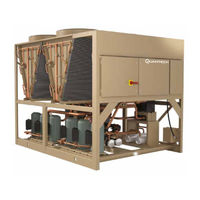
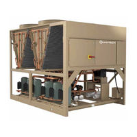
Air-Cooled Scroll Chiller With Brazed Plate Heat Exchanger Style B 60 Hz 4-12 Fan 40 ton to 230 ton 140 kW to 800 kW
Brand:
Quantech
| Category:
Chiller
| Size: 11.92 MB
Table of Contents
Table of Contents
5
Section 1 - General Chiller Information and Safety
11
Introduction
11
Warranty
11
Handling
11
Safety and Quality
11
About this Manual
12
Misuse of Equipment
12
Section 2 - Product Description
15
Introduction
15
General System Description
15
FIGURE 1 - Compressor Enclosure for QTC3040HE
16
TABLE 1 - Canadian Registration Numbers
16
Communications
18
Building Automation System Interface
18
Power Panel
18
Accessories and Options
18
FIGURE 2 - Unit Components (Front)
20
FIGURE 3 - Unit Components (Side)
21
FIGURE 4 - Power Panel Components
22
FIGURE 5 - Power Panel / Control Components
23
TABLE 2 - Complete Pin Number Description
24
FIGURE 6 - Process and Instrumentation Diagram
29
Section 3 - Rigging, Handling and Storage
31
Lifting Weights
31
Delivery and Storage
31
Inspection
31
Moving the Chiller
32
Unit Removal from Shipping Container
32
Lifting Using Lugs
32
Lifting Using Shackles
32
FIGURE 7 - Unit Rigging/Lifting Points
33
Section 4 - Installation
35
Installation Checklist
35
Startup/Commissioning
35
Location and Clearances
35
Spring Isolators (Optional)
36
Compressor Mounting
36
Chilled Liquid Piping
36
Pipework Arrangement
37
Wiring
37
FIGURE 8 - Chilled Liquid System
37
Relief Valves
38
High Pressure Cutout
38
Single-Point Supply Connection - Terminal Block, Non-Fused
39
Disconnect Switch or Circuit Breaker
39
FIGURE 9 - Single-Point Supply Connection - Terminal Block, Non-Fused Disconnect Switch or
39
FIGURE 10 - Control Wiring Inputs
40
TABLE 3 - Chemical Specification of Water
41
FIGURE 11 - Thermal Dispersion Flow Switch
42
FIGURE 12 - (Combine Together)
42
FIGURE 13 - Control Wiring Outputs
44
Section 5 - Technical Data
45
Operational Limitations (English)
45
TABLE 4 - Temperatures and Flows
45
TABLE 5 - Ethylene and Propylene Glycol Correction Factors
46
Physical Data QTC3040T - QTC3225T 60 Hz
47
TABLE 6 - Physical Data (English) 60 Hz
47
Electrical Data
50
Compressor Heaters
50
TABLE 7 - Micropanel Power Supply
50
TABLE 8 - Voltage Range
50
TABLE 9 - Pump Electrical Data (60 Hz)
51
TABLE 10 - Transformer Load
51
TABLE 11 - Electrical Data Without Pumps
52
TABLE 12 - Wiring Lugs
58
Electrical Notes
60
FIGURE 14 - Elementary Wiring Diagram
64
FIGURE 15 - Elementary Wiring Diagram
66
FIGURE 16 - Fan Wiring, Standard Low Sound or Ultra Quiet, QTC3070T - QTC3225T
68
FIGURE 17 - Fan Wiring, High Air Flow
70
FIGURE 19 - Compressor Wiring
76
FIGURE 20 - Power Options Connection Diagram
79
FIGURE 21 - Power Panel
80
FIGURE 22 - Micro Panel Connections
83
Dimensions
84
Weight Distribution and Isolator Mounting Positions
91
FIGURE 23 - Sample Printout Supplied in the Isolator Package and in the Chiller Panel Literature Packet
91
Clearances
92
FIGURE 24 - Unit Clearances - All Models
92
Isolator Locations
93
Isolator Information
96
Section 6 - Commissioning
103
Preparation - Power off
103
Preparation - Power on
105
Section 7 - Unit Controls
111
Introduction
111
IPU II and I/O Boards
111
Transformer
112
Display
112
Keypad
112
Unit Switch
112
Battery Back-Up
112
Programming # of Compressors
112
Status Key
113
FIGURE 25 - Status Key Messages Quick Reference List
118
Display/Print Keys
119
FIGURE 26 - Operation Data
122
Entry Keys
127
Setpoints Keys
128
Schedule/Advance Day Key
129
TABLE 13 - Cooling Setpoint, Programmable Limits and Defaults
130
Program Key
131
TABLE 14 - Program Key Limits and Default
133
FIGURE 27 - Setpoints Quick Reference List
134
TABLE 15 - Program Key Limits and Default
135
Unit Keys
137
FIGURE 28 - Unit Keys Options Programming Quick Reference List
142
Bacnet, Modbus, N2, and E-Link Communications
143
FIGURE 29 - Micro Panel Connections
144
TABLE 16 - Minimum, Maximum and Default Values
144
TABLE 17 - Values Required for Bas Communication
145
TABLE 18 - Real Time Error Numbers
146
TABLE 19 - Native Bacnet, Modbus, and N2 Communications Data Map
147
TABLE 20 - Yorktalk 2 Communications Data Map
151
Section 8 - Unit Operation
157
Unit Operating Sequence
157
Capacity Control
157
Suction Pressure Limit Controls
158
Discharge Pressure Limit Controls
158
Leaving Chilled Liquid Control
158
FIGURE 30 - Leaving Water Temperature Control Example
158
Leaving Chilled Liquid Control Override to Reduce Cycling
159
FIGURE 31 - Setpoint Adjust
159
TABLE 21 - Sample Compressor Staging for Return Water Control
159
TABLE 22 - Return Chilled Liquid Control for 4 Compressors (6 Steps)
159
Leaving Chilled Liquid System Lead/Lag and Compressor Sequencing
160
Return Chilled Liquid Control
160
TABLE 23 - Lead/Lag Return Chilled Liquid Control for 4 Compressors (6 Steps)
160
Return Chilled Liquid System Lead/Lag and Compressor Sequencing
161
Anti-Recycle Timer
161
Anti-Coincidence Timer
161
Evaporator Pump Control and Hydro Kit Pump Control
161
Evaporator Heater Control
162
Pumpdown Control
162
Standard Condenser Fan Control
162
VSD Fan
162
Changing the Switch Point of the Thermal Dispersion Flow Switch
162
FIGURE 32 - Condenser Fan Locations
163
TABLE 24 - QTC3 Standard Condenser Fan Control Using Discharge Pressure Only (2, 3, or 4 Fans Per System)
164
TABLE 25 - QTC3 Standard Condenser Fan Control Using Discharge Pressure Only
165
Load Limiting
166
Compressor Run Status
166
Alarm Status
166
TABLE 26 - Compressor Operation Load Limiting
166
Remote BAS/EMS Temperature Reset Using a Voltage or Current Signal
167
Service Mode
170
Service Mode - Chiller Configuration
170
Service Mode - Analog and Digital Inputs
170
TABLE 27 - I/O Digital Inputs
171
TABLE 28 - I/O Digital Outputs
171
TABLE 29 - I/O Analog Inputs
171
TABLE 30 - I/O Analog Outputs
171
FIGURE 33 - Microboard Layout
172
Checking Inputs and Outputs
173
TABLE 33 - Pressure Transducers
175
FIGURE 34 - I/O Board Relay Contact Architecture
176
TABLE 34 - Data Logging to Flash
177
Optional Printer Installation
179
FIGURE 35 - Printer to Microboard Electrical Connections
180
Troubleshooting
181
TABLE 35 - Troubleshooting
181
Section 10 - Maintenance
183
Compressors
183
Condenser Fan Motors
183
Operating Parameters
183
On-Board Battery Back-Up
183
Overall Unit Inspection
184
Temperature
189
TABLE 36 - si Metric Conversion
189
Advertisement
Quantech QTC3075TSE Manual (62 pages)
AIR-COOLED SCROLL CHILLERS
Brand:
Quantech
| Category:
Chiller
| Size: 8.86 MB
Table of Contents
Table of Contents
3
Introduction
5
Equipment Overview
8
Unit Components
15
Accessories and Options
16
Design Parameters
20
Water Pressure Drop
21
Physical Data and Nominal Ratings
22
Part Load Ratings
24
Unit Dimensions
26
Isolator Locations
33
Isolator Details
36
Electrical Notes
39
Variable Speed Pump Electrical Data
41
Wiring Lugs
42
Electrical Data Without Pumps
44
Wiring Diagram
48
User Control Wiring
50
Notes
51
Application Data
53
Guide Specifications
55
Advertisement
Related Products
Quantech QTC3079THE
Quantech QTC3070T
Quantech QTC3075T
Quantech QTC3070TSE
Quantech QTC3085TSE
Quantech QTC3095TSE
Quantech QTC3090THE
Quantech QTC3050T
Quantech QTC3060T
Quantech QTC3080T
Quantech Categories
Chiller
Air Compressor
Heat Pump
More Quantech Manuals
Login
Sign In
OR
Sign in with Facebook
Sign in with Google
Upload manual
Upload from disk
Upload from URL