
Related Manuals for MTS Sensors Temposonics MH-Series


Summary of Contents for MTS Sensors Temposonics MH-Series
- Page 1 Temposonics ® Magnetostrictive Linear Position Sensors MH-Series Flexible MH Installation Manual...
-
Page 2: Table Of Contents
Temposonics Flexible MH ® Operation Manual Table of contents 1. Introduction ..............................3 1.1 Purpose and use of this manual ................................3 1.2 Used symbols and warnings ..................................3 2. Safety instructions ............................. 3 2.1 Intended use ......................................3 2.2 Forseeable misuse ..................................... 3 2.3 Installation, commissioning and operation .............................. -
Page 3: Introduction
This product may be used only for the applications defined under item 1 and only in conjunction with the third-party devices and components recommended or approved by MTS Sensors. As a prerequsite of proper and safe operation: the product requires correct transport, storage, mounting and commissioning and must be operat ed with utmost care. -
Page 4: Installation, Commissioning And Operation
Under no systems, protective devices etc. are required. In the event of trouble, circumstances will MTS Sensors accept liability in the event of offense shut down the sensor and protect it against accidental operation. -
Page 5: Identification
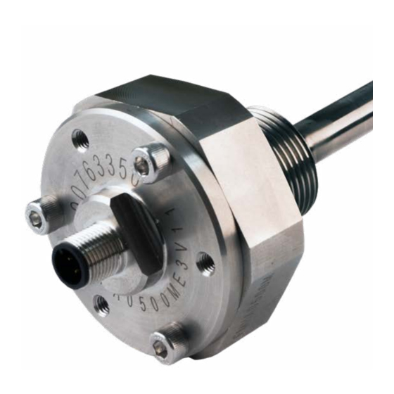
Temposonics Flexible MH ® Installation Manual 3. Identification 3.1 Order code of Flexible MH analog F M H a Sensor model F M H Flexible MH b Design A M33 thread flange, flat end plug B M33 thread flange, M4 female plug Z Base unit (for replacement) c Stroke length M 0500…5000 mm (20 mm increments) -
Page 6: Order Code Of Flexible Mh Canbus
Temposonics Flexible MH ® Installation Manual 3.2 Order code of Flexible MH CANbus F M H a Sensor model F M H Flexible MH b Design A M33 thread flange, flat end plug B M33 thread flange, M4 female plug Z Base unit (for replacement) c Stroke length M 0500…5000 mm (20 mm increments) -
Page 7: Nameplate
Interaction with position magnet fi eld generates torsional strain pulse Principle of operation and system construction Torsional strain pulse propagates The absolute, linear position sensors provided by MTS Sensors Strain pulse detected by converter rely on the company’s proprietary Temposonics magnetostrictive ®... -
Page 8: Styles And Installation Of Flexible Mh
Temposonics Flexible MH ® Installation Manual 4.2 Styles and installation of Flexible MH FMH with flat end plug Sensor electronics housing Null zone Stroke length Dead zone A/F 60 38.9 500…5000 84.8 M12×1-6g R32.5 Threaded flange Sensor rod M33×2-6g Ø12.7 FMH with M4 female thread plug Sensor electronics... - Page 9 Temposonics Flexible MH ® Installation Manual Installation of a rod-style sensor in a fluid cylinder Cavity Dimensions The rod-style version has been developed for direct stroke Notice for metric threaded flanges measurement in a fluid cylinder. Mount the sensor via threaded flange. Thread Z°...
-
Page 10: Replacement Of Sensor
Temposonics Flexible MH ® Installation Manual 4.3 Replacement of sensor The sensor element of the sensor is replaceable. The sensor can be replaced without interrupting the hydraulic circuit. 4.3.1 FMH replacement parts Lid (1 ×) Protective cap Sensor element Sensor element (1 ×) Protective cap M5×12 screw M2×12 screw... -
Page 11: Fmh Replacement Parts
Temposonics Flexible MH ® Installation Manual 4.3.2 FMH replacement steps Step 1: Remove endcaps Remove Remove Step 2: Remove lid Step 2 A Step 2 B • Remove three screws (M5×12 mm) with 4 mm hex key • Insert screws into threaded holes in lid to aid lid removal Step 2 C Step 2 D •... - Page 12 Temposonics Flexible MH ® Installation Manual Step 3: Remove old sensor element Step 3 A Step 3 B • Slowly remove lid entirely • Unplug sensor element from PCB in lid • Be careful not to damage PCB or wires •...
- Page 13 Temposonics Flexible MH ® Installation Manual Step 4: Install new sensor element Step 4 A Step 4 B • Insert new sensor element into sensor cavity • Apply one drop of Loctite 242 to each screw thread • be careful not to bend the sensor element more than 200 mm radius •...
-
Page 14: Electrical Connections
Temposonics Flexible MH ® Installation Manual Analog output 4.4 Electrical connections M12 connector Placement of installation and cabling have decisive influence on the sensor‘s electromagnetic compatibility (EMC). Hence correct 1 do not connected installation of this active electronic system and the EMC of the entire do not connected system must be ensured by using suitable metal connectors, shielded cables and grounding. -
Page 15: Frequently Ordered Accessories
Temposonics Flexible MH ® Installation Manual 4.5 Frequently ordered accessories Position magnets Cord sets and adapter cables Ø 30.5 Ø 19.8 Ring magnet 4 pin M12 to DTM06 connector 4 pin M12 to DT04 connector Part no. 402 316 Part no. 254 597 Part no. -
Page 16: Technical Data
Temposonics Flexible MH ® Installation Manual 5. Technical data 5.1 Technical data Flexible MH-Series analog Output Signal characteristic Analog output restricted by noise or A/D converter of control unit Voltage 0.25…4.75 VDC / 0.5…4.5 VDC Current 4…20 mA Sample rate 2 ms Measured value Position... -
Page 17: Technical Data Flexible Mh-Series Canbus
Temposonics Flexible MH ® Installation Manual 5.2 Technical data Flexible MH-Series CANbus Output Interface CANopen / SAE J1939 Sample rate CANopen: 1 ms; SAE J1939: 20 ms Measured value Position Measurement parameters Resolution ±0.2 mm Linearity ±0.04 % (F.S.) Repeatability ±0.005 % (F.S.) Hysteresis ±0.2 mm... -
Page 18: Appendix
Don’t specify chemical formulas. In the event of suspected penetration of substances into the sensor, Please include safety data sheets of the substances, if applicable. consult MTS Sensors to determine measures to be taken before shipment. Short description of malfunction:... - Page 19 MTS, Temposonics and Level Plus are registered trademarks of MTS Systems Corporation in the United States; MTS SENSORS and the MTS SENSORS logo are trademarks of MTS Systems Corporation within the United States. These trademarks may be protected in other countries. All other trademarks are the property of their respective owners. Copyright © 2018 MTS Systems Corporation. No license of any intellectual property rights is granted.
Need help?
Do you have a question about the Temposonics MH-Series and is the answer not in the manual?
Questions and answers