
Related Manuals for MTS Sensors Temposonics R-Series Ethernet/IP


Summary of Contents for MTS Sensors Temposonics R-Series Ethernet/IP
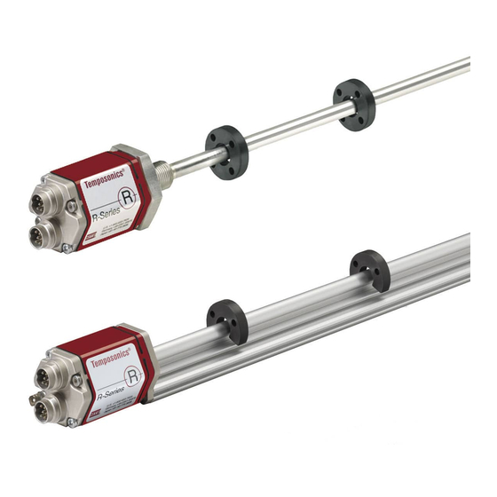
- Page 1 Temposonics ® Magnetostrictive Linear Position Sensors R-Series Ethernet/IP Operation Manual...
-
Page 2: Table Of Contents
1 and item 2 and only in conjunction with the third-party devices 7. Integration in RSLogix5000 ........26 and components recommended or approved by MTS Sensors. As a 7.1 Install the MTS EtherNet/IP EDS file ........28 prerequisite of proper and safe operation, the product requires correct 7.2 Add sensor to I/O configuration using EDS file .... -
Page 3: Forseeable Misuse
. The MTS Sensors obligation is limited to repair or re- placement of any defective part of the unit. No warranty can be taken for defects that are due to improper use or above average stress of the product, as well as for wear parts. -
Page 4: Identification
Temposonics R-Series EtherNet/IP ® Operation Manual 3. Identification 3.1 Order structure of R-Series RP Temposonics order code ® a Sensor model P Profile b Design S Magnet slider, joint on top (Part number: 252182) V Magnet slider, joint at front (Part number: 252184) M U-magnet, OD33 (Part number: 251416-2) c Stroke length X M 0025…5080 mm... -
Page 5: Order Structure Of R-Series Rh
Temposonics R-Series EtherNet/IP ® Operation Manual 3.2 Order structure of R-Series RH Temposonics order code ® a Sensor model Output H Rod 1 EtherNet/IP™ Optional: for multi-position measurement only b Design (Order additional magnets seperately) M Flange M18×1.5 (Standard) g Magnet number for multi-position measurement V Flange M18×1.5 with Fluoroelastomer housing-seal X 02…20 magnets D Flange M18×1.5 bushing on rod end... -
Page 6: Order Structure Of R-Series Rd4
Temposonics R-Series EtherNet/IP ® Operation Manual 3.3 Order structure of R-Series RD4 Temposonics order code ® c Stroke length a Sensor model X M Flange M & C: 0025…5080 mm 4 Detachable sensor electronics Flange S: 0025…2540 mm b Design U Flange M &... -
Page 7: Order Structure Of R-Series Rf
Temposonics R-Series EtherNet/IP ® Operation Manual 3.4 Order structure of R-Series RF Temposonics order code ® a Sensor model F Flexible sensor rod b Design C Basic sensor M Flange M18×1.5-6g S Flange ¾"×16UNF-3A c Stroke length (Longer strokes are available. Contact applications engineering for details.) X M 00100…10060 mm U 0004.0…0396.0 in. -
Page 8: Nameplate (Example)
Temposonics R-Series EtherNet/IP Ağaç isadleme ® Operation Manual 3.5 Nameplate (example) Measuring range (e.g. 1250 mm) Sensor electronics Connection type Design Output version Sensor model Magnet number Part No. RD4CD1S1250MD56N101Z02 MAC adress MAC ID: 00-03-CA-00-2D-5F Serial number S/N: 90595059 Gradient GRD: 9.1044 uS/In | 2789.85 m/s 3.6 Approvals CE certification (only for RP &... -
Page 9: Styles And Installation Of R-Series Rp
Temposonics R-Series EtherNet/IP ® Operation Manual 4.2 Styles and installation of R-Series RP Temposonics RP offers modular construction, flexible mounting configurations and easy installation. Position measurement is non-contact ® via two versions of permanent magnets. • A sliding magnet running in profile housing rails. Connection with the moving machine part is via a ball jointed arm for taking up axial forces. •... - Page 10 Temposonics R-Series EtherNet/IP ® Operation Manual 4.2.2 Installation of RP 4.2.3 Magnet mounting The position sensor can be installed in any position. Normally, Mounting the U-magnet the sensor is firmly installed and the position magnet is fastened The U-magnet is removable and can be used for profile- and rod-style to the mobile machine part.
-
Page 11: Styles And Installation Of R-Series Rh
(1.97) (2.68) Temposonics R-Series EtherNet/IP ® Operation Manual Ø 5.5 4.3 Styles and installation of R-Series RH 35.6 Temposonics RH with a pressure resistant stainless steel flange and sensing rod. They are suitable in all fluid power cylinders and externally in ®... - Page 12 Temposonics R-Series EtherNet/IP ® Operation Manual NOTICE Hydraulics sealing There are two ways for sealing the flange contact surface: For mounting by means of screws, use only a hexagonal flange 1. A sealing by using an O-ring (e.g. 22.4×2.65 mm) in a cylinder width across flats 46 mm (1.8 in.) below the sensor electronics bottom groove (fig.
-
Page 13: Styles And Installation Of R-Series Rd4
Temposonics R-Series EtherNet/IP ® Measuring length (5.24) 100…10060 (3.7) Operation Manual (4…396) (1.93) 11.5 (0.45) 4.4 Styles and installation of R-Series RD4 Temposonics RD4 is a high-performance position sensor with a detached electronics, which allows a flexible installation. The sensor is completely ®... - Page 14 (1.26) Measuring length PUR-cable Ø 6 mm 36.5 25…5080 63.5 / 66* bend radius > 24 mm (1.44) (1…200) * up to 4500 mm Temposonics R-Series EtherNet/IP ® Stroke length Operation Manual Electronics with bottom cable entry for the mesuring rod 24.7 (0.97) (0.3)
- Page 15 Temposonics R-Series EtherNet/IP ® Operation Manual 4.4.1 Mounting distances Active measuring range The technical data of each sensor is checked as well as documented and the active stroke length (useful electrical stroke) with its start and end position is adjusted during final inspection and testing (see Fig.
- Page 16 Temposonics R-Series EtherNet/IP ® Operation Manual 4.4.2 Installation of RD4 with pressure fit flange »S« Cylinder mounting Bore in cylinder Ø 13…17 mm (Ø 0.51…0.67 in.) to push single wires For installation in fluid power cylinders, the standard sensor system with flat connector through.
- Page 17 Temposonics R-Series EtherNet/IP ® Operation Manual 4.4.3 Installation of RD4 with threaded flange »M« & »T« 4.4.4 Installation of RD4 with threaded flange »C« & »D« The sensor’s pipe will be fixed via the threaded flange M18×1.5 or The sensor’s pipe will be fixed via the threaded flange M18×1.5 or 3/4”-16 UNF.
- Page 18 Temposonics R-Series EtherNet/IP ® Operation Manual 4.4.4 Magnet installation Mounting the ring magnet Install the magnet using non-magnetizable material for mounting device, screws, spacers etc. – Max. permissible surface pressure: 40 N/mm – Max. fastening torque for M4 screws: 1 Nm; use washers, if necessary Mounting the U-magnet Using a non-magnetizable mounting device is mandatory.
-
Page 19: Styles And Installation Of R-Series Rf
Measuring range 25…5080 Temposonics R-Series EtherNet/IP ® Operation Manual O-ring 4.5 Styles and installation of R-Series RF (0.98) Measuring range Temposonics RF is a high-performance sensor with a bendable sensor rod. Thanks to its flexible design, the sensor is available for ®... - Page 20 Temposonics R-Series EtherNet/IP ® Operation Manual NOTICE 4.5.2 Installation of RF Mounting of sensor electronics housing requires the use of A flexible sensor requires supports or anchoring to maintain proper 2 non-magnetizable screws M4×59. alignment between sensor rod and the magnet, otherwise the sensor output signal can be interfered or lost.
- Page 21 Temposonics R-Series EtherNet/IP ® Operation Manual 4.5.3 Magnet installation Mounting the ring magnet Install the magnet using non-magnetic material for mounting device, screws, spacers etc. – Max. permissible surface pressure: 40 N/mm – Max. fastening torque for M4 screws: 1 Nm; use washers, if necessary Mounting the U-magnet The U-magnet can be used for rod-style sensors (HD pressure pipe)
-
Page 22: Electrical Connections
Temposonics R-Series EtherNet/IP ® Operation Manual 4.6 Electrical connections Connection types The placement of the sensor and cabling have a decisive influence on The sensor must be connected directly with the control system the sensor’s EMC resistance. Hence correct installation of this active according to wiring diagram: electronic system and the EMC of the entire system must be protected by using suitable... -
Page 23: Accessories
Temposonics R-Series EtherNet/IP ® Operation Manual 4.7 Frequently ordered accessories - Additional options available in our Accessories Guide 551444 Position magnets for profile model (RP) Ø 32.8 57 (2.24) (Ø 1.29) (1.69) (0.55) (0.55) 49 (1.93) Ø 4.3 (0.79) (Ø 0.17) Ø... -
Page 24: Operation
Temposonics R-Series EtherNet/IP ® Operation Manual 5. Operation 6. IP Address Configuration 5.1 Getting started An example of configuring a MTS EtherNet/IP sensor will be shown The sensor is factory-set to its order sizes and adjusted, i.e. the using an Allen-Bradley CompactLogix L35E controller, and the required output signal corresponds exactly to the selected measuring RSLogix 5000 software from Rockwell. -
Page 25: Set The Ip Address Of The Sensor
Temposonics R-Series EtherNet/IP ® Operation Manual 6.1 Setting the IP address of the sensor 6.1.4 Verify that your unique IP address and MAC ID appear in the ‘Relation List’ window. If the relation list window does not Each sensor comes from the factory with BOOTP and DHCP modes contain both MAC ID and IP address, repeat steps 6.1.2 to active, and a unique MAC ID (see sensor label). -
Page 26: Integration In Rslogix5000
Temposonics R-Series EtherNet/IP ® Operation Manual 6.1.7 Click to select your sensor in the ‘Relation List’ box and click 7.1.3 The ‘EDS Wizard’ window opens, click Next, in the ‘Options’ the disable BOOTP/DHCP button. window select Register an EDS file(s) and click “Next”. 6.1.8 The ‘Status’... - Page 27 Temposonics R-Series EtherNet/IP ® Operation Manual 7.1.5 If the installation completed successfully, the ‘EDS File installation test results’ window displays. Click “Next”. Fig. 58: Confirmation of path to the EDS file 7.1.6 The ‘Final Task Summary’ window opens, click “Next”. Fig.
-
Page 28: Add Sensor To I/O Configuration Using Eds File
Temposonics R-Series EtherNet/IP ® Operation Manual 7.2 Add sensor to I/O configuration using EDS file 7.2.2 In the Select Module Type window, choose “R-Series EtherNet/ IP” and click “Create”. 7.2.1 After completing the EDS wizard, return to the main window of RSLogix 5000. -
Page 29: Add Sensor To I/O Configuration W/O Using Eds File
Temposonics R-Series EtherNet/IP ® Operation Manual 7.2.4 Verify that the new sensor is listed in the I/O Configuration tree. 7.3 Add sensor to I/O configuration w/o using EDS file Before you begin, you will need the sensors permanent IP address you recorded in from section 6.1.3. -
Page 30: Verify Generic Ethernet Module
Temposonics R-Series EtherNet/IP ® Operation Manual 7.3.4 In the ‘New Module’ window (shown below) perform steps 7.3.4.1 – 7.3.4.4 to configure the new generic ethernet module to the R-Series EtherNet/IP sensor. NOTICE Enter the “Connection Parameters” and “Comm Format” exactly in the following order in steps 7.3.4.1 –... -
Page 31: Controller Tags Configuration Data
Temposonics R-Series EtherNet/IP ® Operation Manual 7.6 Controller tags configuration data 7.6.1 In the ‘I/O configuration tree’, click to open the ‘Controller Tags’ directory. The controller tag table displays in the left pane (shown below). The description column fields will be blank by default. Fig. - Page 32 Temposonics R-Series EtherNet/IP ® Operation Manual 7.7 Changing Configuration Values In the ‘Value’ column, update the configuration field data if needed. Run/Idle Header Position Data - Magnet 1 Velocity Data - Magnet 1 Fig. 71: Device data tags The following are 'Value' field descriptions, Acceptable values for each field are as follows. 7.7.1 'Value' = Data [0], 'Description' = Data Format: Options are:...
- Page 33 Temposonics R-Series EtherNet/IP ® Operation Manual Used for missing magnet detection purposes only. If the 'Value' = 0, the sensor will determine how many magnets are on the sensor at startup. It will use the determined number of magnets to determine missing magnet status. The missing magnet status is reported in the status attribute of the Position Sensor object and through the LEDs in the connector flange.
-
Page 34: Maintenance And Troubleshooting
8.2 Maintenance The sensor is maintenance-free. 8.3 Repair Repairs on the sensor may be performed only by MTS Sensors or a repair facility explicitly authorized by MTS Sensors. 8.4 List of spare parts No spare parts are available for this sensor. -
Page 35: Technical Data
Temposonics R-Series EtherNet/IP ® Operation Manual 9. Technical data Output Interface EtherNet/IP™ Data transmission rate Max. 100 Mbit/s Measured value Position, velocity / Option: Multi-position and multi-velocity measurement (max. 20 positions/velocities simultaneous) Accuracy Resolution 1…1000 µm selectable Cycle time 1.0 ms up to 2000 mm, 2.0 ms up to 4800 mm, 3.0 ms up to 7620 mm, 4.0 ms up to 10060 mm stroke length Linearity <... -
Page 36: Annex
Personnel exposure to health risks during transport and repair has been removed. Stamp Signature Date GERMANY JAPAN MTS Systems Corporation MTS Sensor Technologie MTS Sensors Technology Corp. Sensors Division GmbH & Co. KG 737 Aihara-machi, 3001 Sheldon Drive Auf dem Schüffel 9 Machida-shi, Cary, N.C. 27513, USA 58513 Lüdenscheid, Germany... -
Page 37: Appendix A - Sensor Reset
Temposonics R-Series EtherNet/IP ® Operation Manual 11. Appendix A - Sensor Reset After the LED’s turn red, remove pins 2 and 4 from ground and let them float again. The In and Out Port LED’s will turn off. 10.1 Step 1: Ground pins 2 and 4 In the event that the IP address has been configured on a sensor, but M8 connector Function... -
Page 38: Appendix B - Port Details
Temposonics R-Series EtherNet/IP ® Operation Manual 12. Appendix B - Port Details C Y L I N D E R P O R T D E T A I L S P O R T D E TA I L ( P D ) F O R T E M P O S O N I C S R H S E N S O R S W I T H H O U S I N G S T Y L E S : NOTES: 1. - Page 39 MTS, Temposonics and Level Plus are registered trademarks of MTS Systems Corporation in the United States; MTS SENSORS and the MTS SENSORS logo are trademarks of MTS Systems Corporation within the United States. These trademarks may be protected in other countries. All other trademarks are the property of their respective owners. Copyright © 2018 MTS Systems Corporation. No license of any intellectual property rights is granted.
Need help?
Do you have a question about the Temposonics R-Series Ethernet/IP and is the answer not in the manual?
Questions and answers