
Related Manuals for MicroNet SP6008PWS


Summary of Contents for MicroNet SP6008PWS
- Page 1 User’s Manual 8-Port Web Smart Switch with PoE Model No.: SP6008PWS http://www.micronet.info...
-
Page 2: Table Of Contents
Table of Contents Chapter 1 Introduction................... 1 1.1 Key Features..................1 1.2 Package Contents................1 Chapter 2 Hardware Installation..............2 2.1 Hardware Installation ............... 3 Chapter 3 Web Administration ..............9 3.1 Administrator..................9 3.2 Port Management ................12 3.3 VLAN Setting ................. 14 3.4 QoS Setting.................. -
Page 3: Chapter 1 Introduction
Chapter 1 Introduction Micronet SP6008PWS 8-Port Web Smart Switch with PoE offers Broadcast storm protection, Port-based VLAN and QoS to manage your networks. Moreover, it automatically detects the presence of IEEE 802.3af-compliant devices (PD) and supplies power to each appliance such as IP Camera, VoIP, and Wireless Access Point. -
Page 4: Chapter 2 Hardware Installation
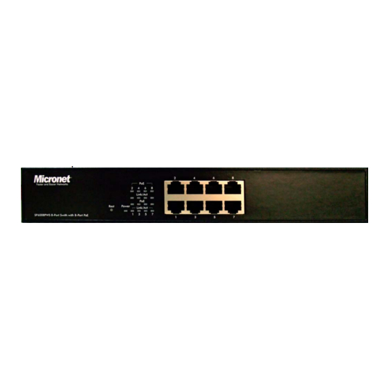
Chapter 2 Hardware Installation Front Panel RJ-45 PoE ports and LED indicators Back Panel Work with AC 90-260V AC, 50-60Hz. LED Indicator For definitions of LED indicators, please refer to the following table: Status Color Description Yellow Power On POWER Power is not connected. -
Page 5: Hardware Installation
2.1 Hardware Installation The setup of the Switch can be performed using the following steps: Step 1: Connect a RJ-45 Ethernet cable from IEEE802.3af-compliant devices (PD) to an available PoE port of SP6008PWS. - Page 6 Make sure the power switch on the rear panel of the SP6008PWS is turned Step 2: off(O). Connect the AC Power Adaptor to SP6008PWS and then to a power outlet.
- Page 7 Tour the system The configuration of the switch can be performed using the following steps: Step1: •Click the Start button followed by Control Panel. • In the Control Panel, double-click the Network Connections. • In the Network Connections window, double-click Local Area Connection.
- Page 8 Step 2: • Click Internet Protocol (TCP/IP) from the components list and then click the Properties Step 3: • In the Internet Protocol (TCP/IP) Properties window, click the Use the following IP address. • Enter the following information:...
- Page 9 IP Address: 192.168.2.xxx ( xxx = 2~254) Subnet Mask: 255.255.255.0 Note: Do not use 192.168.2.1 as this address is reserved for the web management tool. Step 4: Step 5: • The Login screen will show up.
- Page 10 Step1: Step: • Login in with User Username:admin Password :admin • Click OK...
-
Page 11: Chapter 3 Web Administration
Chapter 3 Web Administration On the following home page, select the configuration by clicking the icon. It includes, - Administrator - Port Management - VLAN Setting - QoS Setting - Port Security - Logout 3.1 Administrator Administrator: Configuration... - Page 12 You can change the user name and the password, and click “Update” to confirm the new change. After that, you can reset this switch by power off and then power on to take the new user name and the password effectively. Administrator: System IP Configuration You can change the IP address by typing the new IP address and click “Update”...
- Page 13 It shows this switch MAC address, and you can select “Back to the last display” or “Logout” when the time’s out. Administrator: Load Default Setting to EEPROM You can click “Load” to load the new factory default setting, and then reset the switch by power off and then power on to take it effectively.
-
Page 14: Port Management
Follow the instruction on the screen to update the new firmware. Please contact with your sales agents to get the latest firmware information. 3.2 Port Management Port Management: Port Control Configuration Select the “Port No.” which you want to configure the mode below, “Capability”... - Page 15 Select the “Port No.” which you want to configure the mode below, “TX Rate” is meant you can set the maximum transmission rate of this selected port and choose the full speed or in 128K/256K/512K/1M/2M/4M/8M speed. “RX Rate” is meant you can set the maximum receiving rate of this selected port and choose full speed or in 128K/256K/512K/1M/2M/4M/8M speed.
-
Page 16: Vlan Setting
You can enable or disable the broadcast storm protection feature by clicking “Update”. Port Management: Max Packet Length You can select the maximum packet length setting, 1536 byte or 1552 byte of this switch. 3.3 VLAN Setting VLAN Setting: Group VLAN Setting... -
Page 17: Qos Setting
There are 4 VLAN groups, 01, 02, 03, 04, can be used. You can select a group, and then click the port number which you want to put it into the selected VLAN group. VLAN Setting: Multi to 1 Setting This is a special design for easily setting the switch VLAN into “VLAN Per Port“. - Page 18 You can select the class of service for each port. QoS Setting: High Priority Queue Configuration You can select WRR low weight 1/4 or 1/8. QoS Setting: Customization Diffserv...
-
Page 19: Port Security
Please follow the instruction on the screen to update the setting. 3.5 Port Security... -
Page 20: Logout
When this function is enabled, the port will record the first receiving source MAC address as the security MAC address and only allow the packet which has this MAC address to activate on the port. 3.6 Logout You can click “Logout” to logout. -
Page 21: Chapter 4 Specification
Chapter 4 Specification IEEE 802.3 / IEEE 802.3u/ IEEE 802.3af/ IEEE 802.3x Standards / IEEE 802.1p 8 PSE/Power over Ethernet 10/100Mbps Interface 112 KB Buffer Memory 8K entries Mac Address Table Store and Forward Transmission Method 100Mbps port - 148,800pps Filtering/Forwarding Rates 10Mbps port - 14,880pps VLAN...
Need help?
Do you have a question about the SP6008PWS and is the answer not in the manual?
Questions and answers