
Subscribe to Our Youtube Channel
Related Manuals for MicroNet SP6524PWS


Summary of Contents for MicroNet SP6524PWS
- Page 1 User’s Manual 20-port 10/100/1000M + 4G Combo Web Smart PoE Switch Model No.: SP6524PWS...
- Page 2 Release 0.90 2012 Micronet Communication Inc., All rights reserved. All brand and product names are trademarks or registered trademarks of their respective companies. Publication date: August, 2012 Revision A1...
- Page 3 he information in this document is subject to change without notice. Unless the explicit written permission of Manufacture Corporation, this document in whole or in part shall not be replicated or modified or amended or transmitted, in any from, or by any means manual, electric, electronic, electromagnetic, mechanical, optical or otherwise for any purpose.
- Page 4 documentation, including any revisions made by Manufacture. The copyright notice must be reproduced and included with any copy of any portion of the Software or related documentation. Except as expressly authorized above, Licensee shall not copy or transfer the Software or related documentation, in whole or in part. Licensee also shall not modify, translate, decompile, disassemble, use for any competitive analysis, reverse compile or reverse assemble all or any portion of the Software, related documentation or any copy.
-
Page 5: Table Of Contents
Table of Contents ......................... AUTION ................LECTRONIC MISSION OTICES :......................ARNING VIII INTRODUCTION ....................2 1-1. O 24-P ........2 VERVIEW OF MART WITCH 1-2. C ....................... 3 HECKLIST 1-3. F ......................3 EATURES 1-4. V 24-P ..........5 IEW OF MART WITCH 1-4-1. - Page 6 4-3-5. PoE Status .................... 87 4-3-6. Ping Status .................... 89 4-4. M ....................91 AINTENANCE 4-4-1. Warm Restart ..................92 4-4-2. Factory Default..................93 4-4-3. Software Upgrade ................. 94 4-4-4. Configuration File Transfer..............95 4-4-5. Logout ....................96 5. MAINTENANCE....................97 5-1.
-
Page 7: Revision History
Revision History Release Date Revision 0.90 Aug. 07/2012 Publication date: August, 2012 Revision A1... -
Page 8: Caution
Caution Circuit devices are sensitive to static electricity, which can damage their delicate electronics. Dry weather conditions or walking across a carpeted floor may cause you to acquire a static electrical charge. To protect your device, always: Touch the metal chassis of your computer to ground the static electrical charge before you pick up the circuit device. -
Page 9: Warning
Warning: Self-demolition on Product is strictly prohibited. Damage caused by self- demolition will be charged for repairing fees. Do not place product at outdoor or sandstorm. Before installation, please make sure input power supply and product specifications are compatible to each other. Publication date: August, 2012 viii Revision A1... -
Page 10: User Manual
User Manual About this user’s manual This user’s manual provides instructions on how to install your Web Smart Switch. This guide also covers management options and detailed explanation about hardware and software functions. Overview of this user’s manual Chapter 1 “Introduction” describes the features of 24-port Gigabit Web Smart PoE Switch ... -
Page 11: Introduction
1. Introduction 1-1. Overview of 24-Port GbE Web Smart PoE Switch The 24-port Gigabit Web Smart PoE Switch is a standard switch that meets all IEEE 802.3/u/x/z Gigabit, Fast Ethernet specifications. The switch has 20 10/100/1000Mbps TP ports and 4 Gigabit TP/SFP transceiver slots, It supports http and SNMP interface for switch management. -
Page 12: Checklist
4 10/100/1000Mbps TP or 1000Mbps SFP Fiber dual media auto sense 512KB on-chip frame buffer In SP6524PWS, it supports 370 watts for PoE Power and up to 15.4 watts for 24 ports. Jumbo frame support 9KB Publication date: August, 2012... - Page 13 Programmable classifier for QoS (Layer 2/Layer 3) 8K MAC address and support VLAN ID (1~4094) Per-port shaping, policing, and Broadcast Storm Control Power Saving with "ActiPHY Power Management" and "Perfect Reach Power Management" techniques. IEEE802.1Q-in-Q nested VLAN support ...
-
Page 14: View Of 24-Port Gbe Web Smart Poe Switch
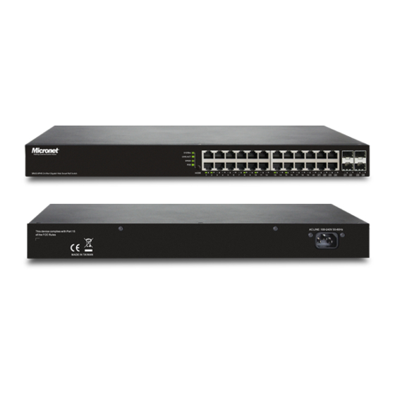
1-4. View of 24-Port GbE Web Smart PoE Switch Fig. 1-1 Full View of 24-PORT GBE WEB SMART PoE SWITCH 1-4-1. User Interfaces on the Front Panel (Button, LEDs and Plugs) There are 24 TP Gigabit Ethernet PoE ports and 4 SFP fiber ports for optional removable modules on the front panel of the switch. -
Page 15: User Interfaces On The Rear Panel
• LED Indicators Color Function System LED POWER Green Lit when +3.3V power is coming up 10/100/1000Ethernet TP Port 1 to 20 LED Lit when connection with remote device is good LINK/ACT Green Blinks when any traffic is present Lit Green when TP link on 1000Mbps speed Green/ Yellow/ Lit Yellow when TP link on 10/100Mbps speed... -
Page 16: View Of The Optional Modules
1-5. View of the Optional Modules In the switch, Port 21~24 include two types of media --- TP and SFP Fiber (LC, BiDi-SC…); they support 10/100/1000Mbps TP or 1000Mbps SFP Fiber with auto-detected function. 1000Mbps SFP Fiber transceiver is used for high-speed connection expansion;... -
Page 17: Installation
2. Installation 2-1. Starting 24-Port GbE Web Smart PoE Switch Up This section will give users a quick start for: Hardware and Cable Installation - Management Station Installation - Software booting and configuration 2-1-1. Hardware and Cable Installation At the beginning, please do first: ... - Page 18 • TP Port and Cable Installation In the switch, TP port supports MDI/MDI-X auto-crossover, so both types of cable, straight-through (Cable pin-outs for RJ-45 jack 1, 2, 3, 6 to 1, 2, 3, 6 in 10/100M TP; 1, 2, 3, 4, 5, 6, 7, 8 to 1, 2, 3, 4, 5, 6, 7, 8 in Gigabit TP) and crossed-over (Cable pin-outs for RJ-45 jack 1, 2, 3, 6 to 3, 6, 1, 2) can be used.
-
Page 19: Cabling Requirements
2-1-2. Cabling Requirements To help ensure a successful installation and keep the network performance good, please take a care on the cabling requirement. Cables with worse specification will render the LAN to work poorly. 2-1-2-1. Cabling Requirements for TP Ports ... - Page 20 2-1-2-3. Switch Cascading in Topology • Takes the Delay Time into Account Theoretically, the switch partitions the collision domain for each port in switch cascading that you may up-link the switches unlimitedly. In practice, the network extension (cascading levels & overall diameter) must follow the constraint of the IEEE 802.3/802.3u/802.3z and other 802.1 series protocol specifications, in which the limitations are the timing requirement from physical signals defined by 802.3 series specification of Media Access Control (MAC) and PHY, and timer from some...
- Page 21 Case1: All switch ports are in the same local area network. Every port can access each other (See Fig. 2-2) Fig. 2-2 No VLAN Configuration Diagram If VLAN is enabled and configured, each node in the network that can communicate each other directly is bounded in the same VLAN area. Here VLAN area is defined by what VLAN you are using.
- Page 22 Case 2b: Port-based VLAN (See Fig.2-4). Fig. 2-4 Port-based VLAN Diagram 1. VLAN1 members could not access VLAN2, VLAN3 and VLAN4 members. 2. VLAN2 members could not access VLAN1 and VLAN3 members, but they could access VLAN4 members. VLAN3 members could not access VLAN1, VLAN2 and VLAN4. 4.
-
Page 23: Configuring The Management Agent Of 24-Port Gbe Web Smart Switch
2-1-3. Configuring the Management Agent of 24-Port GbE Web Smart Switch In the way of web, user is allowed to startup the switch management function. Users can use any one of them to monitor and configure the switch. You can touch them through the following procedures. -
Page 24: Ip Address Assignment
Fig. 2-7 the Login Screen for Web 2-1-4. IP Address Assignment For IP address configuration, there are three parameters needed to be filled in. They are IP address, Subnet Mask, Default Gateway and DNS. IP address: The address of the network device in the network is used for internetworking communication. - Page 25 Network address Host address Class B: IP address range between 128.0.0.0 and 191.255.255.255. Each class B network has a 16-bit network prefix followed 16-bit host address. There are 16,384 (2^14)/16 networks able to be defined with a maximum of 65534 (2^16 –2) hosts per network.
- Page 26 manage practically. Now if we divide it into smaller network by extending network prefix from 16 bits to, say 24 bits, that’s using its third byte to subnet this class B network. Now it has a subnet mask 255.255.255.0, in which each bit of the first three bytes is 1.
- Page 27 65536 65534 Table 2-3 According to the scheme above, a subnet mask 255.255.255.0 will partition a network with the class C. It means there will have a maximum of 254 effective nodes existed in this sub-netted network and is considered a physical network in an autonomous network.
- Page 28 subnet mask such as 255.255.255.x is allowable in this case. Publication date: August, 2012 Revision A1...
-
Page 29: Typical Applications
2-2. Typical Applications The 24-Port GbE Web Smart Switch implements 24 Gigabit Ethernet TP ports with auto MDIX and four slots for the removable module supporting comprehensive fiber types of connection, including LC and BiDi-LC SFP modules. For more details on the specification of the switch, please refer to Appendix A. The switch is suitable for the following applications. - Page 30 Fig. 2-11 Peer-to-peer Network Connection Fig. 2-12 Office Network Connection Publication date: August, 2012 Revision A1...
-
Page 31: Basic Concept And Management
3. Basic Concept and Management This chapter will tell you the basic concept of features to manage this switch and how they work. 3-1. What’s the Ethernet Ethernet originated and was implemented at Xerox in Palo Alto, CA in 1973 and was successfully commercialized by Digital Equipment Corporation (DEC), Intel and Xerox (DIX) in 1980. -
Page 32: Logical Link Control (Llc)
IEEE 802.2 LLC Data Link Layer IEEE802.3 CSMA/CD MAC IEEE 802.3 PLS Physical Layer ANSI X3T9.5 PMD IEEE 802.3 Fiber Coaxial/STP/UTP This above diagram shows the Ethernet architecture, LLC sub-layer and MAC sub-layer, which are responded to the Data Link layer, and transceivers, which are responded to the Physical layer in OSI model. - Page 33 Table 3-1 LLC Format The table 3-1 is the format of LLC PDU. It comprises four fields, DSAP, SSAP, Control and Information. The DSAP address field identifies the one or more service access points, in which the I/G bit indicates it is individual or group address.
-
Page 34: Media Access Control (Mac)
3-3. Media Access Control (MAC) 3-3-1. MAC Addressing Because LAN is composed of many nodes, for the data exchanged among these nodes, each node must have its own unique address to identify who should send the data or should receive the data. In OSI model, each layer provides its own mean to identify the unique address in some form, for example, IP address in network layer. - Page 35 Type/Length Data Pad bit if any 46-1500 Table. 3-4 Ethernet frame structure Preamble (PRE) —The PRE is 7-byte long with alternating pattern of ones and zeros used to tell the receiving node that a frame is coming, and to synchronize the physical receiver with the incoming bit stream. The preamble pattern is: 10101010 10101010 10101010 10101010 10101010 10101010 10101010...
- Page 36 Length. Frame check sequence (FCS) — This field contains a 32-bit cyclic redundancy check (CRC) value, and is a check sum computed with DA, SA, through the end of the data field with the following polynomial. It is created by the sending MAC and recalculated by the receiving MAC to check if the packet is damaged or not.
- Page 37 Ethernet MAC transmits frames in half-duplex and full-duplex ways. In half-duplex operation mode, the MAC can either transmit or receive frame at a moment, but cannot do both jobs at the same time. As the transmission of a MAC frame with the half-duplex operation exists only in the same collision domain, the carrier signal needs to spend time to travel to reach the targeted device.
- Page 38 Parameter 10Base 100Base 1000Base value/LAN Max. collision 100 meters for UTP 100 meters for UTP 100 meters domain DTE to 412 meters for fiber 316 meters for fiber Max. collision 2500 meters 205 meters 200 meters domain with repeater 512 bit times 512 bit times 512 bit times Slot time...
-
Page 39: Flow Control
3-4. Flow Control Flow control is a mechanism to tell the source device stopping sending frame for a specified period of time designated by target device until the PAUSE time expires. This is accomplished by sending a PAUSE frame from target device to source device. - Page 40 Frame Reception In essence, the frame reception is the same in both operations of half duplex and full duplex, except that full-duplex operation uses two buffers to transmit and receive the frame independently. The receiving node always “listens” if there is traffic running over the medium when it is not receiving a frame.
- Page 41 received frame is tagged VLAN and the next two bytes are Tag Control Information (TCI) used to provide user priority and VLAN ID, which are explained respectively in the following table. User Priority 7-0, 0 is lowest priority Bits 15-13 CFI (Canonical Format Indicator) Bit 12 1: RIF field is present in the tag header...
-
Page 42: How Does A Switch Work
3-5. How does a switch work? The switch is a layer 2 Ethernet Switch equipped with 24 Gigabit Ethernet ports and 4 optional modules which support Gigabit Ethernet or 100M Ethernet. Each port on it is an independent LAN segment and thus has 26 LAN segments and 26 collision domains, contrast to the traditional shared Ethernet HUB in which all ports share the same media and use the same collision domain and thus limit the bandwidth utilization. - Page 43 Fig.3-6 Collision Domain Extended Distance Limitations: The diameter of a half-duplex LAN segment is determined by its maximum propagation delay time. For example, in 10M LAN, the most distance of a LAN segment using yellow cable is 2500 meters and 185 meters when using coaxial cable.
- Page 44 Fig. 3-7 How does a switch operate? A Layer 2 switch uses some features of the Data Link layer in OSI model to forward the packet to the destination port(s). Here we introduce some important features of a switch and how they work. MAC address table When a packet is received on a port of switch, the switch first checks if the packet good or bad and extracts the source MAC address (SA) and destination...
- Page 45 do with the priority level a packet has. With the given priority, the scheduler will do the proper action on it. The scheduler has many ways to implement, and different chips may support different schedule algorithms. Most common schedulers are: FCFS: First Come First Service.
-
Page 46: Virtual Lan
3-6. Virtual LAN What is a VLAN? It is a subset of a LAN. Before we discuss VLAN, we must understand what LAN is. In general, a LAN is composed of different physical network segments bridged by switches or bridges which attach to end stations in the same broadcast domain. - Page 47 Fig. 3-9 Now we apply VLAN technology to configure the system shown as the figure above. We can partition the users into the different logical networks which have their own broadcast domain. The traffic will not disturb among these logical networks. The users 1x (x denotes a ~ d) are members of VLAN 1.
- Page 48 It identifies the VLAN membership by layer 3 protocol types, for example IPX, Appletalk, IP, etc. Other VLAN technologies not mentioned above are MAC-based VLAN, IP- based VLAN and so on. Terminology Tagged Frame: A frame, carrying a tag field following the source MAC address, is four bytes long and contains VLAN protocol ID and tag control information composed of user priority, Canonical Format Indicator (CFI) and optional VLAN identifier (VID).
- Page 49 VLAN Identifier: Also referred to as VID. It is used to identify a member whether it belongs to the VLAN group with the VID. The assignable number is 1- 4094. If VID=0, the tagged frame is a priority packet. Both the value of 0 and 4095 also cannot be assigned in VLAN management.
- Page 50 membership, and tagged or untagged for a transmitted packet. When a packet is transmitted out, the VLAN bridge checks the port’s egress list. If the VLAN of the packet is on the egress list of the port on which the packet transmits out, the packet will be transmitted with the priority accordingly.
- Page 51 If we plan to deploy four VLANs in an office and use a switch to partition them, we should check which ports belong to which VLAN first. Assuming a 24-port switch is applied. Publication date: August, 2012 Revision A1...
- Page 52 Name Port Members Marketing 1,2,3,4,5 Service 6,7,20,21,22 Sales 8,9,10,11,12,13,14,15,16 Administration 17,18,19,23,24 Table 3-5 Next, assigns IP address to each VLAN. Usually, we use 10.x.x.x as internal IP block. Because there are total four VLANs in the network, we must assign 4 IP blocks to each of them.
-
Page 53: Link Aggregation
3-7. Link Aggregation Basically, Link Aggregation is to aggregate the bandwidth of more than one port to an assigned logical link. This highly increases total bandwidth to the targeted device. There is more than one Link Aggregation technology in many vendors’ switch products already, which may cause the problem of interoperability. - Page 54 Terminology Link Aggregation: It is a method to have multiple physical links with the same media and speed bundled to be a logical link forming a Link Aggregation Group with a group ID. With the viewpoint of MAC client, each Link Aggregation Group is an independent link. There are three cases of link used in the network, which are switch to switch, switch to station and station to station.
-
Page 55: Operation Of Web-Based Management
4. Operation of Web-based Management This chapter would introduce how to manage your Web Smart Switch and how to configure the 10/100/1000Mbps TP Ports and Gigabit SFP Fiber ports on the switch via web user interfaces. Web Smart Switch provides 20 fixed Gigabit Ethernet TP ports and 4 optional Gigabit dual media ports. -
Page 56: Web Management Home Overview
4-1. Web Management Home Overview After login, System Information would be displayed as Fig. 4-2 illustrated. This page lists default values and shows you the basic information of the switch, including “Switch Status”, “TP Port Status”, “Fiber Port Status”, “Aggregation”, “VLAN”, “Mirror”, “SNMP”, and “Maximum Packet Length”. - Page 57 4-1-1. The Information of Page Layout • On the top part of the information page, it shows the front panel of the switch. Linked ports will be displayed in green color, and linked-off ones will be in black. For the optional modules, the slots with no module will only show covered plates, the other slots with installed modules would present modules.
-
Page 58: Configuration
4-2. Configuration Configuration includes the following functions: System Configuration, Ports Configuration, VLAN Mode Configuration, VLAN Group Configuration, Aggregation, LACP, IGMP Snooping, Mirror, QoS, Storm Control and SNMP. Configuration System Information Ports Configuration VLAN Mode Configuration VLAN Group Configuration VLAN Isolation Aggregation IGMP Snooping Mirroring... -
Page 59: System Information
4-2-1. System Information System configuration is one of the most important functions. Without a proper setting, network administrator would not be able to manage the device. The switch supports manual IP address setting. Fig. 4-3 Function name: System Configuration Function description: Show system description, firmware version, hardware version, MAC address, serial number, active IP address, active subnet mask, active gateway, DHCP server and Lease time left. - Page 60 The simple description of this switch. Firmware Version: The firmware version of this switch. Hardware Version: The hardware version of this switch. MAC Address: It is the Ethernet MAC address of the management agent in this switch. Serial Number: The serial number is assigned by the manufacturer. Active IP Address: Show the active IP address of this switch.
- Page 61 is introduced to solve this problem. Subnet mask uses some bits from host address and makes an IP address looked Network address, Subnet mask number and host address. It is shown in the following figure. This reduces the total IP number of a network able to support, by the amount of 2 power of the bit number of subnet number (2^(bit number of subnet number)).
-
Page 62: Port Configuration
4-2-2. Port Configuration Function name: Port Configuration Function description: Port Configuration is applied for the settings of the ports on the switch. By this function, you can set or reset the values for Mode and Flow Control. Others you could set the power saving mode for switch power consumption. Fig. - Page 63 Link: Show link status of this port. Mode: Set the speed and duplex of the port. If the media is 1Gbps fiber, there are three modes to choose: Auto Speed, 1000 Full and Disable. If the media is TP, the Speed/Duplex is comprised of the combination of speed mode, 10/100/1000Mbps, and duplex mode, full duplex and half duplex.
-
Page 64: Vlan Mode Configuration
4-2-3. VLAN Mode Configuration Web Smart Switch supports Port-based VLAN and Tag-based VLAN (802.1q). Its VLAN mode supports 10 active VLANs and the available VLAN ID range is from 1~4094. VLAN configuration is used to divide a LAN into smaller ones. With proper configuration, you can gain not only improved security and increased performance, but also save a lot of VLAN management effort. -
Page 65: Vlan Group Configuration
4-2-4. VLAN Group Configuration Function name: Tag-Based VLAN Configuration (Tag based VLAN mode) Function description: The VLAN membership configuration for the selected switch can be monitored and modified here. Up to 4094 VLANs are supported. This page allows for adding and deleting VLANs as well as adding and deleting port members of each VLAN. - Page 66 Fig. 4-5-2 Per port configuration Publication date: August, 2012 Revision A1...
- Page 67 Parameter description: VID: VLAN identifier. Each tag-based VLAN group has a unique VID. It appears only in tag-based mode. Member: In modify function this is used to enable or disable if a port is a member of the new added VLAN, “Enable” means it is a member of the VLAN. Just tick the check box () beside the port x to enable it.
- Page 68 Function name: Port-Based VLAN Configuration (Port-based VLAN mode) Function description: It shows the information of VLAN Groups, and allows administrators to maintain them by modifying and deleting each VLAN group. User also can add a new VLAN group by inputting a new VLAN name and VLAN ID. If you are in port-based VLAN, it will just show the ID、Member of the existed port-based VLAN group.
- Page 69 Fig. 4-7 Add or Remove VLAN Member Parameter description: ID (Group ID): When you want to edit a VLAN group, you must select the Group ID field. Then, you will enter Tag Base VLAN Group Setting or Port Base VLAN Group Setting page, which depends on your VLAN mode selection.
-
Page 70: Vlan Port Isolation Configuration
4-2-5. VLAN Port Isolation Configuration Function name: Port Isolation Configuration Function description: Port Isolation provides for an apparatus and method to isolate ports on layer 2 switches on the same VLAN to restrict traffic flow. The apparatus comprises a switch having said plurality of ports, each port configured as a protected port or a non-protected port. -
Page 71: Aggregation
4-2-6. Aggregation The Aggregation (Port Trunking) Configuration is used to configure the settings of Link Aggregation. You can bundle ports by same speed, MAC, and full duplex to be a single logical port, thus the logical port can aggregate the bandwidth of these ports. -
Page 72: Igmp Snooping
4-2-7. IGMP Snooping Function name: IGMP Snooping Configuration Function description: IGMP Snooping lets administrators configure a switch to constrain multicast traffic by listening to (IGMP). After finishing the Internet Group Management Protocol settings, please press <Apply> button to start up the function. Fig. - Page 73 Unregistered IGMP Flooding enabled: ) Just tick the check box ( to enable this function. Default: enable VLAN ID: At the IGMP Enable mode being selected, it will list the VLAN ID number. IGMP Snooping Enabled: ) After IGMP Enabled function start up then user can tick the check box ( enable this function.
-
Page 74: Mirroring Configuration
4-2-8. Mirroring Configuration Function name: Mirror Configuration Function description: Mirror Configuration is provided to monitor the traffic in the network. This switch supports one-port mirror multi-ports. For example, we assume that Port A and Port B are Source Ports, and Port C is Mirror Port respectively, thus, the traffic passing through Port A and Port B will be copied to Port C for monitor purpose. - Page 75 Fig. 4-12 Mirror ports configuration Publication date: August, 2012 Revision A1...
-
Page 76: Snmp
4-2-9. SNMP Any Network Management System (NMS) running the Simple Network Management Protocol (SNMP) can manage the Managed devices equipped with SNMP agent, provided that the Management Information Base (MIB) is installed correctly on the managed devices. It is a protocol used to govern the transfer of information between SNMP manager and agent and traverses the Object Identity (OID) of the management Information Base (MIB), described in the form of SMI syntax. - Page 77 Parameters description: SNMP enable: The term SNMP enable here is used for the activation or de-activation of SNMP. Default is “Disable”. Get/Set/Trap Community: Community name is used as password for authenticating if the requesting network management unit belongs to the same community group.
-
Page 78: Loop Detection
4-2-10. Loop Detection Function name: Loop Detection Configuration Function description: The loop detection is used to detect the presence of traffic. When switch receives packet’s(looping detection frame) MAC address the same as oneself from port, show Loop detection happens. The port will be locked when it received the looping detection frames. - Page 79 Fig. 4-14 Loop Detection Configuration Parameter description: Mode: Controls whether Loop is enabled (as a whole). Detection Unlock Time: The period (in seconds) for which a port will be kept disabled in the event of a loop is detected (and the port action is to shut down the port). State: Show the status on the port.
-
Page 80: Broadcast Strom Protection
4-2-11. Broadcast Strom Protection Function name: Broadcast Strom Protection configuration Function description: When the broadcast packets received by the switch exceed the threshold configured, the port will be blocked for a period of time which can be set. After a configured time, the switch will detect whether the broadcast packets received on the port still exceed the threshold. - Page 81 Fig. 4-15 Rate Limit Configuration Publication date: August, 2012 Revision A1...
- Page 82 Parameter description: Mode: Controls whether Broadcast Strom Protection is enabled (as a whole). Packet Per Second: It is a threshold. When the broadcast packet traffic in a second is higher than the threshold configured, the Broadcast Strom Protection enable. Unlock Time: The period (in seconds) for which a port will be kept disabled in the event of a loop is detected (and the port action is to shut down the port).
-
Page 83: Poe
4-2-12. PoE Power Over Ethernet (PoE) technology allows IP telephones, wireless LAN access points, and other powered devices (PDs) to receive power and transfer data over existing LAN cabling. Function name: Power over Ethernet configuration Function description: In PoE Port Management function, user can configure the settings about PoE. The switch complies with IEEE 802.3af protocol and be capable of detecting automatically that whether the device linked to the port on the switch is PD (Powered Device) or not. - Page 84 Fig. 3-16 Parameter description: PoE Enabled: To evoke to enable which port supply the power to the PD. Priority: Publication date: August, 2012 Revision A1...
- Page 85 Three options are offered for the user to choose, including Normal, Low and High. Default is Normal. The switch will stop supplying the power to the port based on the order of the priority LowNormalHigh in case total power required by all PDs linked to the switch excesses the power limit.
-
Page 86: Qos(Quality Of Service) Configuration
4-2-13. QoS(Quality of Service) Configuration offers powerful QoS function. This function supports VLAN-tagged switch priority that can make precedence of 8 priorities, and DSCP(Differentiated Services Code Point) on Layer 3 of network framework. Fig. 4-17 QoS Configuration Function name: QoS Configuration Function description: While setting QoS function, please select QoS Mode in drop-down menu at first. - Page 87 Each Priority can select any of Queue. In Default, Priority 0 is mapping to Queue normal, Priority 1 is mapping to Queue low, Priority 2 is mapping to Queue low, Priority 3 is mapping to Queue normal, Priority 4 is mapping to Queue medium, Priority 5 is mapping to Queue medium, Priority 6 is mapping to Queue high, and Priority 0 is mapping to Queue high.
- Page 88 The QoS setting would apply to all ports on the switch if one of the following values is selected: All Low Priority, All Normal Priority, All Medium Priority, or All High Priority. Port Number When Custom is selected for Prioritize Traffic, you may assign specific Port Number for DSCP Configuration.
-
Page 89: Monitoring
4-3. Monitoring There are six functions contained in the monitoring function. Monitoring Statistics Overview Detailed Statistics IGMP Status PoE Status Ping Publication date: August, 2012 Revision A1... -
Page 90: Statistics Overview
4-3-1. Statistics Overview Function name: Statistics Overview for all ports Function description: The section describes to the Port statistics information and provides overview of general traffic statistics for all switch ports. Fig. 4-20 Statistics Overview for all ports Parameter description: Tx/Rx Bytes: The number of received and transmitted bytes per port. -
Page 91: Detailed Statistics
4-3-2. Detailed Statistics Function name: Detailed Statistics Function description: Display the detailed counting number of each port’s traffic. In the Fig. 4-26, the window can show all counter information each port at one time. Fig. 4-21 Detailed Statistics for each port Parameter description: Rx Packets: The counting number of the packet received. - Page 92 packet. Rx Error Packets: Show the counting number of the received error packets. Tx Packets: The counting number of the packet transmitted. TX Octets: Total transmitted bytes. Tx High Priority Packets: Number of Tx packets classified as high priority. Tx Low Priority Packets: Number of Tx packets classified as low priority.
- Page 93 Number of 65 ~ 126-byte frames in good and bad packets transmitted. Tx 128-255 Bytes: Number of 127 ~ 255-byte frames in good and bad packets transmitted. Tx 256-511 Bytes: Number of 256 ~ 511-byte frames in good and bad packets transmitted. Tx 512-1023 Bytes: Number of 512 ~ 1023-byte frames in good and bad packets transmitted.
-
Page 94: Igmp Status
4-3-4. IGMP Status Function name: IGMP Status Function description: Display IGMP status. In Fig. 4-22, the window shows VLAN ID for each multicast group. Fig. 4-22 IGMP Status Parameter description: VLAN Id: Show VLAN Id for each multicast group. Querier: Show the group membership queries status. - Page 95 Queries received: To count the group membership queries received. V1 Reports: When a host receives a group membership query, it identifies the groups associated with the query and determines to which groups it belongs. The host then sets a timer, with a value less than the Max Response Time field in the query, for each group to which it belongs.
-
Page 96: Poe Status
4-3-5. PoE Status Function name: PoE State Function description: Display the information about the PoE status. Fig. 4-23 Parameter description: Vmain: The volt is supplied by the PoE. Imain: The sum of the current that every port supplies. Pconsume: The sum of the power that every port supplies. Power Limit: Publication date: August, 2012 Revision A1... - Page 97 The maximal power that the switch can supply (Read Only). Temperature: The temperature of the chip on PoE. Port No: Port number. Port On: Show whether the port is supplying the power to the PD or not. AC Disconnect Port Off: Port is turned off due to the AC Disconnect function.
-
Page 98: Ping Status
4-3-6. Ping Status Function name: Ping Status Function description: To set up target IP address for ping function and display ping status. In Fig. 4- 24, the window shows the ping information. Fig. 4-24 Ping Parameter description: Ping Parameters: Target IP address: Set up a Target IP address to ping. - Page 99 Ping Results: Target IP address: Show the active target IP address. Status: Show the result of the ping status. Received replies: Show the received replies number of times. Request timeouts: Show the timeout of request. Average Response times (In ms): Show the average response time in milliseconds.
-
Page 100: Maintenance
4-4. Maintenance There are five functions contained in the maintenance function. Maintenance Warm Restart Factory Default Software Upgrade Configuration File Transfer Logout Publication date: August, 2012 Revision A1... -
Page 101: Warm Restart
4-4-1. Warm Restart Web Smart Switch offers many approaches to reboot your switch, such as: power up, hardware reset and software reset. You can press RESET button in the front panel of your switch to reset the device and to retrieve default settings. After upgrading software, you have to reboot the device to have new configuration take effect. -
Page 102: Factory Default
4-4-2. Factory Default Function name: Factory Default Function description: Factory Default provides the function to retrieve default settings and replace current configuration. Except the IP address setting, all settings will be restored to the factory default values when “Factory Default” function is performed. -
Page 103: Software Upgrade
4-4-3. Software Upgrade Function name: Software Upgrade Function description: You can just click Browse button to retrieve the file you want in your system to upgrade your switch. Fig. 4-27 Software Upgrade Publication date: August, 2012 Revision A1... -
Page 104: Configuration File Transfer
4-4-4. Configuration File Transfer Function name: Configuration File Transfer Function description: You can backup your switch’s configuration file into your computer folder in case accident happens. In addition, uploading backup configuration file into a new or a crashed switch can save much time and avoid mistakes. Fig. -
Page 105: Logout
4-4-5. Logout In addition to auto logout function we just mentioned in system configuration section, the switch also allows administrators to logout manually by Logout function. Function name: Logout Function description: The switch allows you to logout the system to prevent other users from the system without the permission. -
Page 106: Maintenance
5. Maintenance 5-1. Resolving No Link Condition The possible causes for a no link LED status are as follows: The attached device is not powered on The cable may not be the correct type or is faulty The installed building premise cable is faulty ... -
Page 107: Appendix A Technical Specifications
Appendix A Technical Specifications Features 20 (10/100/1000Mbps) Gigabit Ethernet (TP) switching ports are compliant with IEEE802.3, 802.3u, 802.3z and 802.3ab. 4 Gigabit TP/SFP fiber are dual media ports with auto detected function. Non-blocking store-and-forward shared-memory Web-Smart switched. ... - Page 108 Hardware Specifications Standard Compliance: IEEE802.3/802.3ab / 802.3z / 802.3u / 802.3x Network Interface: Configuration Mode Connector Port 10/100/1000Mbps Gigabit TP 1 - 8 NWay TP (RJ-45) 9,10 1000 FDX *SFP 1000Base-SX Gigabit Fiber (Option) 9,10 1000 FDX *SFP 1000Base-LX Gigabit Fiber (Option) 9,10...
- Page 109 Diagnostic LED: System LED : Power Per Port LED: 10/100/1000M TP Port 1 to 20 : LINK/ACT, SPD 1000M SFP Fiber Port 21 to 24 : LINK/ACT, SPD AC Line Power Requirement Voltage 100240 V Frequency 5060 Hz Consumption ...
Need help?
Do you have a question about the SP6524PWS and is the answer not in the manual?
Questions and answers