
Related Manuals for MicroNet SP676C


Summary of Contents for MicroNet SP676C
- Page 1 User’s Manual Gigabit Smart Switch Model No.: SP676C/SP684C World Wide Web: www.micronet.com.tw ; www.micronet.info...
-
Page 2: Table Of Contents
Table of Content ------------------------------------------------------------------------------------------------------------------------- 1. Introduction................3 1.1 Package Contents ............3 1.2 Features ................3 1.3 Physical Description ............4 2. Installation .................5 2.1 Preparing the Site.............5 2.2 Settling the Switch............5 2.3 Connecting to Power ............5 2.4 Connecting to Network .............5 3. Web-based Interface Configuration ...........7 3.1 Setting Up Connection .............7 3.2 Main Menu ...............7 3.3 Configuration..............10... -
Page 3: Introduction
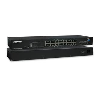
Introduction Micronet SP676C/SP684C Gigabit Smart Switch delivers wire speed Gigabit performance and web-based management functions, suitable for high performance workgroups and server applications. With 16/24 10/100/1000Mbps RJ-45 ports and 4 shared SFP slots for fiber optic connection, it provides a perfect solution for huge data transmission and preserves the great flexibility of network infrastructure. -
Page 4: Physical Description
1.3 Physical Description SP676C Front Panel SP684C Front Panel Please refer to the following description for LED indicators and reset button: Restore Default Button Use this button to reset the switch or restore factory default settings. To reset the switch, press the button once. -
Page 5: Installation
Installation 2.1 Preparing the Site Select the site that meets the following requirements: Characteristic Requirement Temperature (0 to 40˚C) 32 to 104˚F Humidity 5% ~ 90%, non-condensing 2.2 Settling the Switch Mounted to 19-inch standard rack Locate the accessories provided in the product package. Use the rack-mount brackets and screws to install the switch into any EIA 19”... - Page 6 It may cause electric shock or any possible harm to you if the power is not switched off. Step 2: Prepare cable with corresponding connectors for each type of port in use. Step 3: Connect one end of the cable to the switch and the other end to a desired device. Step 4: Once the connections between two end-devices are made successfully, turn on the power.
-
Page 7: Web-Based Interface Configuration
3.1 Setting Up Connection In the web browser, enter the IP address “192.168.1.1” as SP676C/SP684C’s URL. Key in username/password to pass the login step below. The factory default value of username/password is “admin/admin”. And then, you can enter the main page. - Page 8 Monitoring * Statistics Overview * Detailed Statistics Maintenance * Restart * Factory Default * Smart Boot * Software Upload On the left side, the main menu tree for web is listed in the page. According to the function name in boldface, all functions can be divided into three parts, including “Configuration”, “Monitoring”...
- Page 9 on “Detailed Statistics” button and the window will show. On the top side, it shows the front panel of the switch. In the front panel, the linked ports will display green; as to the ports, which are link off, they will be dark.
-
Page 10: Configuration
3.3 Configuration Eleven functions, including System, Port, VLAN, Aggregation Configuration, Quality of Service, Mirror, Rate Limit, SNMP and Discover is contained in this function folder for system and network management. Each of them will be described in detail orderly in the following sections. - Page 11 Parameter description: MAC Address: It is the Ethernet MAC address of the management agent in this switch. S/W Version: The sfotware version of this switch. IP Address: Users can configure the IP settings and fill in new values. Then, click <Apply> button to update.
-
Page 12: Port
32 bits Network ID Host ID Network ID Host ID Subnet number Subnet mask is used to set the subnet mask value, which should be the same value as that of the other devices resided in the same network it attaches. Default: 255.255.255.0 Gateway: Set an IP address for a gateway to handle those packets that do not meet the... - Page 13 Parameter description: Link: Shows the link status of each port. The column lights green with the link speed while there is valid connection on this port. Mode: Select a speed for this port. “Auto Speed” enables auto-negotiation. “Disable” stop the port from functioning. Flow Control There are two modes to choose in flow control, including Enable and Disable.
-
Page 14: Vlan Mode Configuration
3.3.3 VLAN Mode Configuration VLAN divides the network members into groups to reduce packets collisions and improve the network efficiency. The switch supports 802.1Q tag-based VLAN. Please follow the instructions to configure. To add new VLAN groups, * Fill in a VLAN id from 2 to 4094 in the “VLAN\Port” column. * Select the ports for each VLAN groups. - Page 15 Port: Port Number 1~16/24 Egress: Select “tagged” in the drop list to enable the PVID checking and tag inserting of one port, and select “untagged” to cancel. For example, if an Egress-tagged port receives an untagged frame, it will be transmitted as a PVID tagged frame. For the detail tagging status, please refer to the following table.
-
Page 16: Aggregation/ Trunk Configuration
3.3.4 Aggregation/ Trunk Configuration To set up the Port trunk groups, put the ports number into the same Aggregation group. There are eight groups to choose. Don’t forget to click the “Apply” to save the setting. There are three aggregation modes for you to setup, SMAC, DMAC, and XOR. SMAC mode selects the path of packets according to source MAC while DMAC mode selects path according to destination MAC. - Page 17 Parameter description: Port-based mode QoS: The port-based QoS allows users to configure certain ports as high or low priority To give priority level for each port: Select “Port” in the “Mode” column for those ports that are going to perform port-based QoS.
- Page 18 DSCP mode QoS: The DSCP mode QoS gives packet priority by the types of the incoming packets. We distinguish those packets according to the “Delay”, “Throughput” and “Reliability” information attaching on the packet. The types are listed as the following table: Bit 0 (Delay) Bit 1 (Throughput) Bit 3 (Reliability) 0 (Normal) 0 (Normal)
-
Page 19: Mirror Configuration
3.3.6 Mirror Configuration Mirror Configuration is to monitor the traffic of the network. For example, we assume that Port A and Port B are Sniffer Port and Monitor Port respectively, thus, the traffic passed by Port B will be copied to Port A for monitoring. Parameter description: Sniffer Port: Set up the port for monitoring. -
Page 20: Snmp
3.3.8 SNMP This device supports SNMP-management, which allows network administrators to monitor and configure this device with SNMP software. To allow this device to be managed via SNMP: *. Select “enable” in the drop list. *. Specify a trap IP. A trap IP is the destination port for sending trap information, which is usually the IP address of network administrators. -
Page 21: Discovery
3.3.9 Discovery After installing series of our switches, the discovery management tool helps users to search and get access to those switches within the LAN. 3.4 Monitoring There are two functions contained in the monitoring function. Monitoring Statistics Overview Detailed Statistics 3.4.1 Statistics Overview The function of Statistics Overview collects any information and provides the counting summary about the traffic of the port, no matter the packet is good or bad. -
Page 22: Detailed Statistics
Parameter description: Tx Bytes: Total transmitted bytes. Tx Frames: The counting number of the packet transmitted. Rx Bytes: Total received bytes. Rx Frames: The counting number of the packet received. Tx Errors: Number of bad packets transmitted. Rx Errors: Number of bad packets received. 3.4.2 Detailed Statistics Display the detailed counting number of each port’s traffic. - Page 23 Rx Packets: The counting number of the packet received. RX Octets: Total received byte Rx Broad- and Multicast: Show the counting number of the received broadcast/ multicast packet. Tx Packets: The counting number of the packet transmitted. TX Octets: Total transmitted bytes. Tx Broad- and Multicast: Show the counting number of the transmitted broadcast/ multicast packet.
-
Page 24: Restart
3.5. Maintenance 3.5.1 Restart To restart the system, click the “Yes” button. The system restarts and shows the authentication window. Please fill in the username and password to continue. 3.5.2 Factory Default To restore the factory default value, click the Yes button. The IP address of the device will also be configured as factory-default setting, which is 192.168.1.1. -
Page 25: Software Upload
3.5.4 Software Upload This “Software Upload” page allows users to upgrade firmware for this switch. Note: This new firmware is going to be applied on the other flash that you select in “Smart Boot”, that is, the new firmware is going to be applied on the flash that is NOT chosen as the booting flash. -
Page 26: Specifications
Specifications Model SP676D SP684D IEEE standard IEEE802.3 10BASE-T IEEE802.3u 100BASE-TX IEEE802.3ab 1000BASE-T IEEE802.3x Flow control IEEE802.1Q VLAN interoperability IEEE802.1P Traffic prioritization Interface 16*10/100/1000Mbps 24*10/100/1000Mbps RJ-45 RJ-45 ports ports 4 * shared SFP slots 4 * shared SFP slots Cable Connection RJ-45 (10BASE-T): Cat.3,4,5 UTP/STP RJ-45 (100BASE-TX): Cat.5 UTP/STP RJ-45 (1000BASE-T): Cat. -
Page 27: Appendix- Command Line Interface
5. Appendix- Command Line Interface Start-up and Terminal configuration To start-up the command line interface, please connect a PC COM port to the RS-232 connector and activate a terminal emulation software (e.g. HyperTerminal of Windows.) The terminal emulation software should be started as the following configuration: Data rate: 115200 baud Data format: 8 data bits, 1 stop bit and no parity Flow control: none. - Page 28 Command Hierarchy After logging in, press ? + <enter> to show the 9 command groups. System - System commands Console - Console commands Port - Port commands VLAN - VLAN commands Aggr - Aggregation commands - QoS commands Mirror - Mirror commands - IP commands SNMP - SNMP commands...
- Page 29 Command Description The following session introduces the command structure of the command line interface. Command groups: System - System commands Console - Console commands Port - Port commands VLAN - VLAN commands Aggr - Aggregation commands - QoS commands Mirror - Mirror commands - IP commands SNMP...
- Page 30 [<username>]: String of up to 16 characters (default: Show user name). System Password [<password>] Description: Set or show the console password. The empty string ("") disables the password check. [<password>]: Password string of up to 16 characters. System Systemname [<systemname>] Description: Set or show the system name.
- Page 31 Port Commands Commands at Port level: Port Configuration [<portlist>] Port Mode [<portlist>] [<mode>] Port Flow Control [<portlist>] [enable|disable] Port Admin [<portlist>] [enable|disable] Port MaxFrame [<portlist>] [<framesize>|reset] Port Statistics [<portlist>] [clear] ------ #Note: If your want to change maxframe bigger than 1518. The [Flow Control] should be enabled! Port Configuration [<portlist>] Description:...
- Page 32 Port Admin [<portlist>] [enable|disable] Description: Set or show the state for the port. [<portlist>] : Port list (default: All ports). [enable|disable]: Enable or disable port state (default: Show state). Port MaxFrame [<portlist>] [<framesize>|reset] Description: Set or show the maximum frame size in bytes (including FCS) for frames received on the port.
- Page 33 VLAN Commands Commands at VLAN level: VLAN Configuration [<portlist>] VLAN Add <vidlist> [<portlist>] VLAN Delete <vidlist> VLAN Lookup VLAN Egress [<portlist>] [untagged|tagged] VLAN PVID [<portlist>] [<vid>|none] VLAN Frame Type [<portlist>] [all|tagged] VLAN Configuration [<portlist>] Description: Show the VLAN aware mode, port VLAN ID and accepted frame type for the port and the permanently stored VLAN table.
- Page 34 VLAN Egress [<portlist>] [untagged|tagged] Description: Set or show the VLAN egress mode setting for the port. Egress untagged ports will strip the VLAN tag from received frames. Egress tagged ports will not strip the tag from received frames [<portlist>]: Port list (default: All ports). [tagged|untagged]: (default: Show egress tag setting).
- Page 35 Aggregation Commands Commands at Aggr level: Aggr Configuration Aggr Add <portlist> Aggr Delete <portlist> Aggr Lookup <portlist> Aggr Mode [smac|dmac|xor] Aggr Configuration Description: Shows the aggregation groups and the aggregation mode. Aggr Delete <portlist> Description: Delete link aggregation group. <portlist>: Port list. Aggregations including any of the ports will be deleted. Aggr Lookup <portlist>...
- Page 36 QoS Commands Commands at QoS level: QoS Configuration [<portlist>] QoS Mode [<portlist>] [tag|port|diffserv] QoS Port [<portlist>] [<class>] QoS Tagprio [<portlist>] [<tagpriolist>] [<class>] QoS DiffServ [<dscpno>] [<class>] <class> range: low|normal|medium|high QoS Configuration [<portlist>] Description: Show the configured QoS mode and the priority setting of all ports. [<portlist>]: Port list (default: All ports).
- Page 37 QoS DiffServ [<dscpno>] [<class>] Description: Set or show the IP Differentiated Services mapping. [<dscpno>]: IP DSCP number, 0-7. [<class>] : range: low|normal|medium|high Mirror Commands Mirror Configuration Mirror Port [<port>] Mirror Source [<portlist>] [enable|disable] Mirror Configuration Description: Show the mirror destination port and mirror mode for source ports. Mirror Port [<port>] Description: Set or show the mirror destination port.
- Page 38 IP Commands Commands at IP level: IP Configuration IP Setup [<ipaddress> [<ipmask> [<ipgateway>]]] [<vid>] IP Web management [enable|disable] IP Configuration Description: Show IP configured IP address, mask, gateway, VLAN ID and mode. IP Setup` Description: Setup or show IP configuration. [<ipaddress>]: IP address.
- Page 39 SNMP Setup [enable|disable] Description: Activate or deactivate the SNMP. [enable|disable]: Enable/disable SNMP (default: Show SNMP mode). SNMP Trap [<IP Address>] Description: Set or show SNMP traps destination. <IP Address>: IP address to send traps to. (default: Show trap configuration) Ratelimit Commands Commands at Storm Control level: Ratelimit Configuration Ratelimit Setup <traffic type >...
- Page 40 Ratelimit Egress Description: Set or show the shaper configuration. [<portlist>] : Port list (default: All ports). [enable|disable] : Enable or disable shaper. [<rate>] : Disable or set leaky bucket rate in Kbit/s [0-3968k] (default: Show shaper rate). Ratelimit Ingress Description: Set or show the policer configuration.
Need help?
Do you have a question about the SP676C and is the answer not in the manual?
Questions and answers