Table of Contents
Advertisement
Quick Links
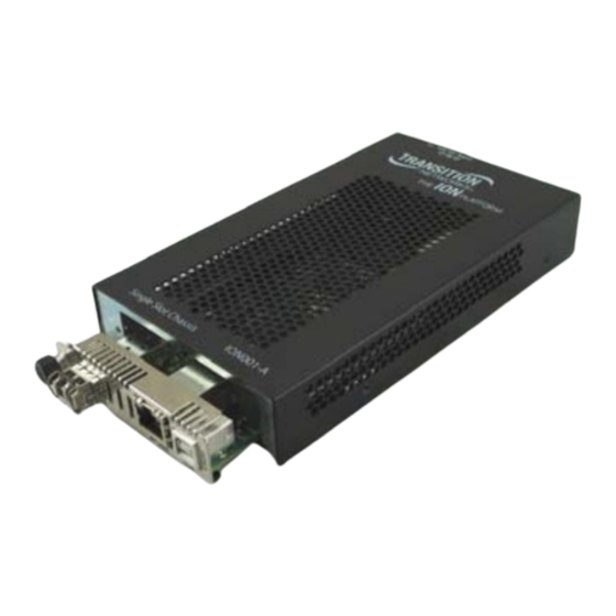
ION001‐A
Single‐Slot ION Chassis
Install Guide
Desktop installation
Supports WMBP wall mount brackets
Unmanaged Chassis
Supports any ION slide‐in card that requires 6 Watts or less of power (C4120‐1048 is not
supported)
Fan‐less design
External AC power
Supports IP addressable managed ION slide‐in cards
Contents
Introduction .................................................................................................................................................. 1
Ordering Information . ................................................................................................................................... 2
Optional Accessories (sold separately) . .................................................................................................... 2
Kit Contents . .................................................................................................................................................. 2
Power Supply Included ................................................................................................................................. 2
Installation .................................................................................................................................................... 3
Installing a Slide‐In Card ........................................................................................................................... 3
Powering the Chassis . ............................................................................................................................... 4
Grounding the Chassis .............................................................................................................................. 4
Specifications ................................................................................................................................................ 5
Troubleshooting . ........................................................................................................................................... 6
Related Manuals and Help . ........................................................................................................................... 6
Contact Us . .................................................................................................................................................... 7
Compliance Information ............................................................................................................................... 7
Declaration of Conformity ........................................................................................................................ 7
FCC Regulations ........................................................................................................................................ 8
Canadian Regulations ............................................................................................................................... 8
Record of Revisions . ...................................................................................................................................... 8
Introduction
The Transition Networks ION001‐A Single Slot chassis is designed for installing a single Transition
Networks ION slide‐in card. The ION001‐A is a 1‐slot ION chassis that is design for network edge
deployments, allowing a single ION card to be deployed as a stand‐alone unit. This chassis provides a
method of mounting one single‐wide ION slide‐in media converter module and includes an external AC
power supply.
33419 Rev. B
https://www.transition.com/
Page 1 of 8
Advertisement
Table of Contents

Related Manuals for Transition Networks ION001-A


Summary of Contents for Transition Networks ION001-A
- Page 1 ION001‐A Single‐Slot ION Chassis Install Guide Desktop installation Supports WMBP wall mount brackets Unmanaged Chassis Supports any ION slide‐in card that requires 6 Watts or less of power (C4120‐1048 is not supported) Fan‐less design External AC power Supports IP addressable managed ION slide‐in cards Contents Introduction .............................. 1 Ordering Information ............................ 2 Optional Accessories (sold separately) ..................... 2 Kit Contents .............................. 2 Power Supply Included .......................... 2 Installation .............................. 3 Installing a Slide‐In Card ........................... 3 Powering the Chassis .......................... 4 Grounding the Chassis .......................... 4 Specifications .............................. 5 Troubleshooting ............................ 6 Related Manuals and Help ...
-
Page 2: Ordering Information
Transition Networks ION001‐A Install Guide Ordering Information Part Number Description 1‐Slot Chassis for the ION Platform, AC Powered. The Single‐Slot ION chassis is ION001‐A intended for installing any 6W or less ION slide‐in card. Optional Accessories (sold separately) Part Number Description External Power Supply 24‐60 VDC and 24‐42 VAC RMS. For use with all TN stand‐ SPS‐2460‐SA alone media converters and some chassis. IONFP ION Blank face plate WMBP Wall Mount Bracket: 5" [127 mm] SFP Modules SFP and SFP+ modules supported on some slide‐in cards; see the TN SFP webpage. Kit Contents The ION001‐A kit includes: □ One ION001‐A Single Slot chassis □ One Power Supply □ One Power Cord □ Four rubber feet ... -
Page 3: Installation
Transition Networks ION001‐A Install Guide Installation Installing a Slide-In Card CAUTION: Wear a grounding device and observe electrostatic discharge precautions when installing the slide‐in card, into the single‐slot chassis. Failure to observe this caution could result in damage to the slide‐in card. Note: The maximum power delivery capacity for the ION001‐A Single Slot chassis is 6 Watts. To install a slide‐in‐card into the single‐slot chassis: 1. Refer to the user guide that came with the slide‐in card to ensure that any DIP switches or jumpers on the module’s circuit board are set correctly for the site installation. 2. Carefully align the slide‐in card to the chassis installation guides and slide it fully into the installation slot, as shown below. 3. Ensure that the slide‐in card is firmly seated inside the chassis. 4. Push in and rotate the attached panel fastener screw to secure the slide‐in card to the single‐ chassis frame. 33419 Rev. C https://www.transition.com/ Page 3 of 8 ... -
Page 4: Powering The Chassis
Transition Networks ION001‐A Install Guide Powering the Chassis To supply power to the single‐slot chassis: 1. Connect the barrel connector on the power adapter to the ION001‐A back panel Power port. 2. Connect the power adapter plug to AC power. 3. Use the cable tie down to secure the power supply cord and the barrel connector. 4. Verify that the single‐slot chassis is powered by observing the lit LED(s) on the installed slide‐in card. See the related slide‐in card manual for LED and other details. For an optional DC power source see the SPS‐2460‐SA External Power Supply 24‐60 VDC and 24‐42 VAC rms. Go to https://www.transition.com and click Search then type in the Search box. SPS‐2460‐SA Grounding the Chassis The single‐slot chassis comes equipped with grounding lugs located on its back panel. They require a grounding conductor wire terminated with a two‐hole, compression‐type, grounding connector (not provided). The grounding wire (must be a copper conductor) is not included with the chassis and must be provided by the customer/installer. The electrical‐conducting path from the single‐slot chassis must: • Flow via the grounding lugs to the common bonding network (CBN) for telecom installations, or to an alternative approved grounding system (if required) for non‐telecom installations. • Be of sufficiently low impedance to conduct fault currents likely to be imposed on the converter. • Enable proper operation of any over‐current protection devices. Ground Wire Size The wire size of the Protective Earth (ground) conductor should be greater than or equal to the wire size ... -
Page 5: Specifications
Transition Networks ION001‐A Install Guide Grounding Method The conductor must be fastened to the grounding lugs with the enclosed antirotation star‐washers and lug‐nut fasteners. The torque requirement for the connector lug‐nut fasteners is specified by the connector’s manufacturer. To properly ground the single‐slot chassis: 1. Obtain one (1) two‐hole, compression‐type, grounding connector. 2. Attach the grounding conductor to the chassis by placing the two‐hole connector onto the grounding lugs and fasten with the enclosed lockwashers/lug‐nuts at the proper torque (per the manufacturer’s specification). 3. Attach the opposite end of the grounding conductor to the common‐bonding network (CBN) for telecom, or to earth ground (if required) for non‐telecom installations. Specifications For use with Transition Networks Model ION001‐A Single Slot chassis or equivalent. Note: The ION001‐A Single Slot chassis is Class A compliant. Status LEDs None, Power indicator is on the slide‐in card Dimensions Width: 4" [102 mm] W x 7.1” [180 mm] D x 1.2” [30.48 mm] (H) Power Supply External AC/DC power supply included, 120‐240VAC input, 12VDC Output (See selected Slide‐In Card manual for power consumption data) Operating Temp. 0°C to 50°C ... -
Page 6: Troubleshooting
• Contact Technical Support. See Contact Us below. YES • Proceed to step 3. 3. Check the power requirement for the installed slide‐in card: • Power requirement must be 6 W or less. • For additional assistance, see Contact Us below. Related Manuals and Help For Transition Networks A printed documentation card is shipped with each ION001-A chassis. Application Notes, Brocures, Case Studies, Data Sheets, Specifications, Webinars, White papers, etc. go to https://www.transition.com/support/library/ (no registration required). For Transition Networks Drivers, Firmware, Release Notes, Manuals (Install Guides, Quick Start Guides, User Guides) go to the Product Support webpage at https://www.transition.com/support/product‐ support/ (logon required). Other ION system and related device manuals include. 1. Product Documentation Postcard, 33504 2. -
Page 7: Declaration Of Conformity
Transition Networks ION001‐A Install Guide Contact Us Technical Support: Technical support is available 24‐hours a day US and Canada: 1‐800‐260‐1312 International: 00‐1‐952‐941‐7600 Main Office tel: +1.952.941.7600 | toll free: 1.800.526.9267 | fax: 952.941.2322 sales@transition.com | techsupport@transition.com | customerservice@transition.com Address Transition Networks 10900 Red Circle Drive Minnetonka, MN 55343, U.S.A. Web: https://www.transition.com Compliance Information Declaration of Conformity 33419 Rev. C https://www.transition.com/ Page 7 of 8 ... -
Page 8: Fcc Regulations
Transition Networks ION001‐A Install Guide FCC Regulations This equipment has been tested and found to comply with the limits for a Class A digital device, pursuant to part 15 of the FCC rules. These limits are designed to provide reasonable protection against harmful interference when the equipment is operated in a commercial environment. This equipment generates, uses, and can radiate radio frequency energy and, if not installed and used in accordance with the instruction manual, may cause harmful interference to radio communications. Operation of this equipment in a residential area is likely to cause harmful interference. In which case, the user will be required to correct the interference at the user’s own expense. Canadian Regulations This digital apparatus does not exceed the Class A limits for radio noise for digital appa‐ratus set out on the radio interference regulations of the Canadian Department of Communications. Le présent appareil numérique n'émet pas de bruits radioélectriques dépassant les limites applicables aux appareils numériques de la Class A prescrites dans le Règlement sur le brouillage radioélectrique édicté par le ministère des Communications du Canada. CAUTION: RJ connectors are NOT INTENDED FOR CONNECTION TO THE PUBLIC TELEPHONE NETWORK. Failure to observe this caution could result in damage to the public telephone network. Der Anschluss dieses Gerätes an ein öffentlickes Telekommunikationsnetz in den EGMitgliedstaaten verstösst gegen die jeweligen einzelstaatlichen Gesetze zur Anwendung der Richtlinie 91/263/EWG zur Angleichung der Rechtsvorschriften der Mitgliedstaaten über Telekommunikationsendeinrichtungen einschliesslich der gegenseitigen Anerkennung ihrer Konformität. In accordance with European Union Directive 2002/96/EC of the European Parliament and of the Council of 27 January 2003, Transition Networks will accept post usage returns of this product for proper disposal. The contact information for this activity can be found in the 'Contact Us' portion of this document. Record of Revisions Rev Date Notes A 6/9/10 ...
Need help?
Do you have a question about the ION001-A and is the answer not in the manual?
Questions and answers