Table of Contents
Advertisement
Available languages
Available languages
Advertisement
Chapters
Table of Contents

Related Manuals for Delta 36-267


Summary of Contents for Delta 36-267
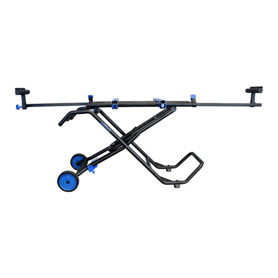
- Page 1 FOLDING MITER SAW STAND www.DeltaMachinery.com Instruction Manual To reduce risk of serious injury, thoroughly read and comply with all warnings 36-267 and instructions inthis manual and on product. KEEP THIS MANUAL NEAR YOUR STAND FOR EASY REFERENCE AND TO INSTRUCT OTHERS...
-
Page 2: Table Of Contents
TABLE OF CONTENTS PRODUCT SPECIFICATIONS ........... 2 ADJUSTMENTS ................. 9 SAFETY INFORMATION ............2 Workpiece Supports and Stop Plates ........UNPACKING ................4 Rail Extensions ................Package Contents ............... Collapsing the stand for transport ..........Hardware .......................... Mounting bracket clamping pressure ASSEMBLY .................6 PARTS, SERVICE OR WARRANTY ASSISTANCE .... - Page 3 GENERAL SAFETY RULES WARNING FAILURE TO FOLLOW THESE RULES MAY RESULT IN SERIOUS PERSONAL INJURY. • FOR YOUR OWN SAFETY, READ AND UNDERSTAND THE INSTRUCTION MANUAL BEFORE OPERATING THE PRODUCT STAND. KEEP WORK AREA CLEAN AND WELL LIT. Cluttered or poorly-lit work areas, surfaces and benches can lead to accidents.
-
Page 4: Unpacking
3. Using the illustration below, locate and identify all parts and hardware to make sure they are all accounted for before discarding packing material or beginning to assemble. NOTE: If any part is missing or damaged, DO NOT attempt to assemble the product and call DELTA® Power Equipment Corporation Customer Care at 1-800-223-7278. - Page 5 UNPACKING PACKAGE CONTENTS DESCRIPTION (QTY) 1. Miter saw stand (1) 2. Handle (1) 3. Mounting bracket (2) 4. Workpiece support w/stop plate (2) 5. Vertical stabilizer (1) 6. Wheel (2) 7. Rubber Feet (2 Small and 2 Large) 8. Knob – Large (2) HARDWARE DESCRIPTION (QTY) •...
-
Page 6: Assembly
ASSEMBLY Tools Required for Assembly (not included): Phillips screwdriver, socket set, and an adjustable wrench. PIVOT BOLT 1. Lay the stand on its side. 2. Pull the rear folding support (A) toward the Align holes handle tube openings (B) in order to align the holes in the rear folding support and front folding support. -
Page 7: Front Handle And Wheels
ASSEMBLY FRONT HANDLE AND WHEELS 1. Attach handle (A) by inserting the tubes into the top of the front folding supports. The handle should be angled down. 2. Align holes and secure using two M8 x 20mm self-tapping screws (B) and Phillips head screwdriver. -
Page 8: Attaching Miter Saw To The Stand
(D) up through the slots in the bracket and NOTE: The DELTA 36-267 miter saw stand is designed through the mounting holes in the saw. Secure to work with virtually all miter saws. In the event that with an M8 hex nut (E). -
Page 9: Adjustments
Position the stop plate at the desired height and re-tighten the lock knob. RAIL EXTENSIONS The DELTA 36-267 Miter Saw Stand features left and right rail extensions to accomodate longer work pieces. To extend the right or left extensions: Depress the rail lock (A) and pull the rail out to the desired length. -
Page 10: Parts, Service Or Warranty Assistance
Two Year Limited New Accessories Warranty DELTA will repair or replace, at its expense and at its option, any machine accessory which in normal use has proven to be defective in workmanship or material, provided that the customer returns the product... -
Page 11: Specifications Du Produit
SOMMAIRE SPECIFICATIONS DU PRODUIT ..........11 REGLAGES ................18 INSTRUCTIONS DE SECURITE IMPORTANTES ....11 Supports et plaques de butée des pièces de travail ....DEBALLAGE ................13 Rallonges de rail ............... Contenu des cartons ............Plier l'établi pour le transporter ..........Accessoires de montage .......... - Page 12 REGLES GENERALES DE SECURITE LE NON RESPECT DE CES REGLES PEUT CAUSER DES BLESSURES SERIEUSES. AVERTISSEMENT: • POUR SA SECURITE PERSONNELLE, LIRE LE MANUEL D’UTILISATION AVANT D'UTILISER L'ETABLI. GARDER L'AIRE DE TRAVAIL PROPRE ET BIEN ECLAIREE. Des zones, surfaces ou bancs de travail encombrés et mal éclairés favorisent les accidents.
-
Page 13: Deballage
Pour toute question relative à l'utilisation de cet outil ou au contenu de ce manuel, veuillez tout d'abord arrêter d'utiliser l'outil et appeler le Service Clientèle de DELTA® Power Equipment Corporation au 1-800-223-7278. DEBALLAGE 1. Retirer tous le contenu des cartons de transport. -
Page 14: Contenu Des Cartons
DEBALLAGE DESCRIPTION DU CONTENU DES CARTONS (QTE) 1. Établi pour scie à onglet (1) 2. Poignée (1) 3. Fixations de montage (2) 4. Supports de pièce de travail avec plaque de butée (2) 5. Stabilisateur vertical (1) 6. Roues (2) 7. -
Page 15: Assemblage
ASSEMBLAGE O u t i l s ( n o n i n c l u s ) n é c e s s a i re s p o u r l'assemblage : un tournevis Phillips, un jeu de douille, et une clé... -
Page 16: Poignées Avant Et Roues
ASSEMBLAGE POIGNEE AVANT ET ROUES 1. Attacher la poignée (A) en insérant les tubes dans le sommet des supports pliables avant. La poignée devrait former un angle vers le bas. 2. Aligner les trous et fixer à l'aide de deux vis auto taraudeuse M8 x 20mm (B) et d'un tournevis à... -
Page 17: Fixer La Scie À Onglet Sur L'établi
4. Engager vers le haut un boulon hexagonal M8 x NOTE: L'établi pour scie à onglet DELTA 36-267 est 55mm (C) muni d'une rondelle M8 (D) au travers conçu pour recevoir théoriquement toutes scies des rainures dans la fixation et du trou de montage à... -
Page 18: Reglages
2. Placer la plaque de butée à la hauteur désirée, puis resserrer le bouton de verrouillag. RALLONGES DE RAIL L'établi pour scie à onglet DELTA 36-267 comprend des rallonges gauche et droite de rail pour permettre le travail de pièces plus longues. Pour étendre les rallonges gauche et droite: 1. -
Page 19: Plier L'établi Pour Le Transporter
REGLAGES PLIER L'ÉTABLI POUR LE TRANSPORTER L'établi se replie pour être transporté facilement et ce éventuellement avec la scie installée dessus. Pour plier l'établi pour le transporter: 1. S'assurer que la scie est débranchée et le fil électrique enroulé, et que les fixations de montage sont fixées sur les rails et verrouillées. -
Page 20: Assistance Pieces Detachees, Service Apres-Vente Ou Garantie
Centres SAV Agréés. Pour obtenir des informations supplémentaires sur vos produits DELTA® ou obtenir des pièces, bénéficier du SAV ou de la garantie, ou connaître le centre SAV le plus proche, appeler le 1-800-223-7278. -
Page 21: Especificaciones Del Producto
TABLA DE CONTENIDO ESPECIFICACIONES DEL PRODUCTO ........ 21 AJUSTES ..................28 INFORMACIÓN DE SEGURIDAD .......... 21 Soportes para piezas y placas de detención ......DESEMBALAJE ...............23 Extensiones ............Contenido de la caja ............Plegando la base para transporte ..........Tornillería ................Presión de soporte de montaje .......... - Page 22 NORMAS GENERALES DE SEGURIDAD NO SEGUIR ESTAS NORMAS PUEDE RESULTAR EN HERIDAS PERSONALES GRAVES. • POR SU PROPIA SEGURIDAD, LEA EL MANUAL DE INSTRUCCIONES ANTES DE USAR LA BASE DEL PRODUCTO. CONSERVE EL ÁREA DE TRABAJO LIMPIA Y BIEN ILUMINADA. Áreas y mesas abarrotadas o mal iluminadas inducen a accidentes.
-
Page 23: Desembalaje
Lleve ropa de protección y lave las áreas expuestas con agua y jabón. Si tiene cualquier duda o pregunta relativas al uso de su herramienta o los contenidos de este manual, no utilice la herramienta y llame al Centro de Atención al Cliente de DELTA® Power Equipment Corporation al 1-800-223-7278. DESEMBALAJE 1. - Page 24 DESEMBALAJE DESCRIPCIÓN DEL CONTENIDO (CANT.) 1. Base de sierra ingletadora (1) 2. Asa (1) 3. Fijaciones (2) 4. Soportes para piezas con placa de detención (2) 5. Estabilizador vertical (1) 6. Ruedas (2) 7. Pies de goma (2 grandes y 2 pequeños) 8.
-
Page 25: Ensamblaje
ENSAMBLAJE Herramientas necesarias para el montaje (no incluidas): Destornillador Phillips, llaves de tubo, llave inglesa graduable. PERNO DE PIVOTE 1. Ponga la base sobre su lateral. Alinee los 2. Tire del soporte plegable trasero (A) hacia las aberturas de los tubos para el asa (B) para ori cios alinear los orificios de los soportes plegables trasero y delantero. -
Page 26: Asa Frontal Y Ruedas
ENSAMBLAJE ASA DELANTERA Y RUEDAS 1. Monte el asa (A) insertando los tubos en la parte superior del soporte plegable frontal. El ángulo del asa debe ir hacia abajo. 2. Alinee los orificios y asegure usando dos tornillos autorroscantes M8x20mm (B) y un destornillador Phillips. -
Page 27: Acoplando La Sierra Ingletadora A La Base
4. Introduzca un perno hexagonal M8x55mm (C) con NOTA: La base para sierra ingletadora DELTA 36-267 una arandela M8 (D) en sentido ascendente a está diseñada para poder funcionar con prácticamente través de lasranuras de la fijación y a través de los... -
Page 28: Ajustes
EXTENSIONES DE LOS PERFILES La base para sierra ingletadora DELTA 36-267 tiene extensiones para los perfiles derecho e izquierdo que permiten acomodar piezas de trabajo más largas. Para prolongar las extensiones derecha o izquierda: 1. -
Page 29: Plegando La Base Para Transporte
AJUSTES PLEGANDO LA BASE PARA SU TRANSPORTE La base se pliega para un transporte más fácil y puede plegarse y moverse aún con la sierra montada. Para plegar la base para su transporte: 1. Ensure the saw is unplugged and cord wrapped and the Asegúrese que la sierra está... -
Page 30: Piezas, Revisión O Asistencia En Garantía
PIEZAS, REVISIÓN O ASISTENCIA EN GARANTÍA Todas las máquinas y accesorios DELTA® se fabrican con estándares de alta calidad y se revisan y reparan en una red de Centros de Servicio Autorizados. Para obtener más información con respecto a si producto de calidad DELTA®... - Page 32 99 ROUSH ST ANDERSON, SC 29625-3113 (800) 223-7278 www.DeltaMachinery.com Copyright © 2014 DELTA® Power Equipment Corporation DPEC002900 03-19-14...
Need help?
Do you have a question about the 36-267 and is the answer not in the manual?
Questions and answers