
Subscribe to Our Youtube Channel
Related Manuals for Delta Amplon TFM-RT-5/6K


Summary of Contents for Delta Amplon TFM-RT-5/6K
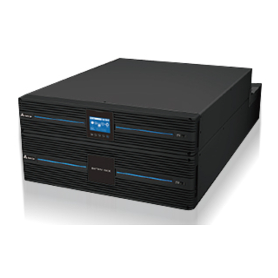
- Page 1 The power behind competitiveness Delta UPS - Amplon Family Transformer Cabinet 5/ 6/ 8/ 10 kVA User Manual www.deltapowersolutions.com...
- Page 2 Failure to heed these instructions and warnings will void the warranty. Copyright © 2019 by Delta Electronics Inc. All Rights Reserved. All rights of this User Manual (“Manual”), including but not limited to the contents, information, and figures are solely owned and reserved by Delta Electronics Inc.
-
Page 3: Table Of Contents
Table of Contents Table of Contents Chapter 1 : Introduction & Safety Instructions -------------------- 1 Chapter 2 : Package Inspection ----------------------------------------- 4 Chapter 3 : Rear Panels --------------------------------------------------- 5 Chapter 4 : Installation ----------------------------------------------------- 9 Installation Placement ------------------------------------------ 9 Installation --------------------------------------------------------10 Rack-mount Configuration -----------------------------------10 Tower Configuration -------------------------------------------12 Connection Warning -------------------------------------------13... -
Page 4: Chapter 1 : Introduction & Safety Instructions
If you experience a problem with the TFM-RT, please refer to Chapter 6: Obtaining Service or contact Delta service personnel for assistance. The TFM-RT is ONLY intended to be installed in an indoor temperature con- trolled environment that is free of conductive contaminants. It is not intended for use in a computer room as defined in the Standard for the Protection of Elec- tronic Computer/ Data Processing Equipment ANSI/ NFPA75. - Page 5 AC current leakage. ONLY Qualified Service Personnel can perform Installation and Servicing of the TFM-RT. Delta accepts no liabilities and is not limited to: injury to the Ser- vice Personnel, or damages to the TFM-RT, the power supply, or the connected equipment caused by the incorrect installation or servicing of the power supply system.
- Page 6 Life support policy As a general policy, Delta does not recommend the use of any of our products in life support applications where failure or malfunction of the product can be reasonably expected to cause failure of the life support device or to significantly affect its safety or effectiveness.
-
Page 7: Chapter 2 : Package Inspection
Chapter 2 Package Inspection Chapter 2 : Package Inspection Once you receive the product it should be visually inspected for damage that may have occurred in shipping. Immediately notify the carrier and place of purchase if any damage is found. Warranty claims for damage caused by the carrier will not be honored by the manufacturer. -
Page 8: Chapter 3 : Rear Panels
Chapter 3 : Rear Panels TFM-RT-5/6K (TFM502R4RT2N035) Rear Panel AC INPUT OUTPUT BREAKER-3 250V AC 20A INPUT BREAKER 250V AC 30A OUTPUT BREAKER-4 250V AC 20A OUTPUT SOCKET-2 OUTPUT SOCKET-1 TRANSFORMER PROTECTION 20A MAX. 30A MAX. BREAKER 8A (Rear View) Description Load 1: 208V output receptacle (L6-30R x 1). - Page 9 Chapter 3 Rear Panels Description The input power cord is for connecting to the UPS. TFM-RT-5/6K (TFM502R5RT2N035) Rear Panel AC INPUT OUTPUT BREAKER-1 OUTPUT BREAKER-3 250V AC 20A 250V AC 20A INPUT BREAKER 250V AC 30A OUTPUT BREAKER-2 OUTPUT BREAKER-4 250V AC 20A 250V AC 20A TRANSFORMER PROTECTION...
- Page 10 Description The input circuit breaker will trip when the load exceeds the TFM-RT’s power rating. The TFM-RT’s circuit breaker will trip when that the TFM-RT becomes overheated. The input power cord is for connecting to the UPS. TFM-RT-8/10K (TFM103R4RT2N035) Rear Panel OUTPUT SOCKET-1 / 20A MAX.
- Page 11 Delta online type UPS is required. 2. TFM-RT-5/6K must be connected to the UPS through the optional Delta Maintenance Bypass Box (model MBB-RT-5K-S). If you want to purchase the Delta Maintenance Bypass Box (MBB), please contact your local dealer or customer service.
-
Page 12: Chapter 4 : Installation
Chapter 4 : Installation Please refer to the block diagram and related information below for correct installa- tion. Breaker Breaker Breaker Output Input To Fan Auxpower To Relay Breaker Relay Breaker Relay Breaker 4.1 Installation Placement The TFM-RT is ONLY intended to be installed in an indoor temperature controlled environment that is free of conductive contaminants. -
Page 13: Installation
Chapter 4 Installation 4.2 Installation Be sure to read this user manual thoroughly before installing the TFM-RT. Place the unit in the final desired location and complete the rest of the installation procedures. Please refer to 4.3 Rack-mount Configuration to install the unit into a rack. The TFM-RT are extremely heavy. - Page 14 2. Follow steps through to install the TFM-RT into the provided rail kit. See the figure below. Adjust the length of the rail according to the rack. Securely tighten the wing nuts. Secure the rail to the rack with the enclosed screws. Slide the TFM-RT onto the rail and secure to the rack with the enclosed screws.
-
Page 15: Tower Configuration
Chapter 4 Installation 4.4 Tower Configuration The tower configuration allows the user to install the TFM-RT in the up-right posi- tion. WARNING: 1. Use two or more people when installing the TFM-RT. 2. The TFM-RT is extremely heavy. Use the appropriate number of person- nel when installing the TFM-RT. -
Page 16: Connection Warning
Front View Front View Tower Stand (TFM-RT-5/6K) Tower Stand Tower Stand Extender (TFM-RT-8/10K) (TFM-RT-5/6K) (TFM-RT-8/10K) 4.5 Connection Warnings 1. When connecting the TFM-RT-8/10K to the UPS, it is highly recommended that you install the protective devices. Please refer to the below table and figure. Suggested TFM-RT Suggested Protective Device... - Page 17 Chapter 4 Installation 1. TFM-RT-8/10K Input/ Output cable selection: Tightening Torque Temperature Rating TFM-RT-8/10K (For AC Wiring) 90°C #6 AWG (Cu) 22 lb-in In accordance with National Electrical Code (NEC), install a suitable conduit and bushing. NOTE : Use copper wire only. 2.
- Page 18 supply's output terminal block labeled N and secure. c) Connect the green wire labeled G on the input power cable to the power supply's output terminal block's ground terminal and secure. 3. Re-install the terminal block cover plate on the TFM-RT-8/10K. 4.
-
Page 19: Chapter 5 : Operation
Chapter 5 Operation Chapter 5 : Operation 5.1 Start up the Step Down Transformer (TFM-RT) The input of the TFM-RT must be connected to the output of the power supply. The equipment must be plugged into the output receptacles on the TFM-RT. 1. -
Page 20: Chapter 6 : Obtaining Service
Chapter 6 : Obtaining Service If the step down transformer (TFM-RT) requires service, 1. Verify there are no tripped circuit breakers. A tripped circuit breaker is the most common issue. 2. Contact Delta service personnel. Amplon Transformer Cabinet... -
Page 21: Appendix 1 : Specifications
Appendix 1 Specifications Appendix 1 : Specifications Model TFM-RT-5/6K TFM-RT-8/10K Topology Isolation, Step Down Transformer, Sine Wave Voltage 208 Vac Frequency 60 Hz Current 24 Amps 49.2 Amps Input (Max) Protection Resettable Circuit Breaker Attached #10 AWG Terminal Block Connection power cord Hardwire only 120 Vac... - Page 22 Model TFM-RT-5/6K TFM-RT-8/10K Operating/ Storage Hu- 0 ~ 95% (non-condensing) midity Environmental Operating 0 ~ 3000 m (0 ~ 10000 ft); Elevation 0 ~ 1000 m (0 ~ 3300 ft) (without derating) Audible Noise 55 dBA 60 dBA Dimensions 17.3 × 22.2 × 3.5 inch 17.3 ×...
-
Page 23: Appendix 2 : Warranty
Appendix 2 Warranty Appendix 2 : Warranty Seller warrants this product, if used in accordance with all applicable instructions, to be free from original defects in material and workmanship within the warranty period. If the product has any failure problem within the warranty period, Seller will repair or replace the product at its sole discretion according to the failure situation. - Page 27 - Regional Office The United States Australia Delta Electronics (Americas) Ltd. Delta Energy Systems Australia Pty Ltd. 46101 Fremont Blvd. Fremont, CA 94538 Unit 20-21, 45 Normanby Road, Notting Hill VIC 3168, Australia T +1 510 344 2157 T +61 3 9543 3720 E ups.na@deltaww.com...
- Page 28 5013274401...
Need help?
Do you have a question about the Amplon TFM-RT-5/6K and is the answer not in the manual?
Questions and answers