Table of Contents
Advertisement
Available languages
Available languages
Quick Links
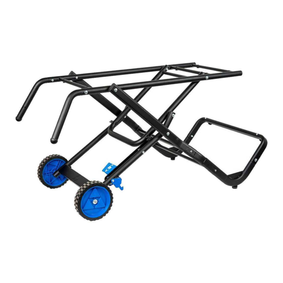
GRAVITY FOLDING STAND FOR
96-107 AND 96-110 WET TILE/STONE SAWS
Français (13)
Español (25)
www.DeltaMachinery.com
Instruction Manual
Manual d'utilisation
Manual de instrucciones
To reduce the risk of serious injury, thoroughly read and comply with all warnings and instructions in this manual and on product
KEEP THIS MANUAL NEAR YOUR PRODUCT FOR EASY REFERENCE AND TO INSTRUCT OTHERS
96-014
Advertisement
Chapters
Table of Contents

Related Manuals for Delta 96-014


Summary of Contents for Delta 96-014
- Page 1 GRAVITY FOLDING STAND FOR 96-107 AND 96-110 WET TILE/STONE SAWS Français (13) Español (25) 96-014 www.DeltaMachinery.com Instruction Manual Manual d’utilisation Manual de instrucciones To reduce the risk of serious injury, thoroughly read and comply with all warnings and instructions in this manual and on product...
-
Page 2: Table Of Contents
TABLE OF CONTENTS PRODUCT SPECIFICATIONS .......... 2 ASSEMBLE PEDAL ASSEMBLY TO MAIN FRAME GENERAL SAFETY RULES ..........2 ASSEMBLY..............7 SAFETY SYMBOLS ............2 ASSEMBLE SUPPORT LEG ROD ASSEMBLY TO WORK AREA SAFETY ............ 3 PEDAL ASSEMBLY............8 PERSONAL SAFETY ............3 ASEMBLE UPPER END OF SUPPORT LEG ROD TOOL SAFETY ............. -
Page 3: General Safety Rules
GENERAL SAFETY RULES WORK-AREA SAFETY Tool Safety KEEP THE WORK AREA CLEAN AND WELL LIT. Cluttered KEEP ALL GUARDS IN PLACE and in working order. benches and dark areas invite accidents. • AVOID ACCIDENTAL STARTING. Be sure the switch • DON’T USE IN A DANGEROUS ENVIRONMENT. Don’t is in the “Off”... -
Page 4: Specific Safety Instructions
SPECIFIC SAFETY INSTRUCTIONS FOR WET TILE/STONE SAW STAND • Never put your fingers or hands in the path of moving BE SURE to read and understand all parts when folding and unfolding stand. instructions in this manual before using • Never use a hand position where a sudden slip could this Wet Tile/ Stone Saw and Stand. -
Page 5: Product Content
PRODUCT CONTENT Product Contents Description (QTY) Pedal Assembly (1) Wrench (1) Main Frame Assembly (1) Carriage Bolt M8 x 87mm (2) Right Leg Support Rod (1) Carriage Bolt M8 x 78mm (4) Left Leg Support Rod (1) Plastic Spacer (6) Wheels (2) M8 Locknut (6) Left Handle (1) -
Page 6: Assembly
ASSEMBLY VERTICAL SUPPORT LEG ASSEMBLY Attach the Right Leg Support Rod (Right Leg Support Rod not shown in Figure 1) and Left Leg Support Rod (D) to the Support Rod Connect Tube (G). (Figure 1) Note: Rubber Feet will point outward away from support rods G and D. -
Page 7: Pedal Assembly
ASSEMBLY Attach both Cross Tube Supports (H & I) with M6 x 40 mm Hex Bolts (O) using Wrench (J). Repeat this step on the other side of this assembly. (Figure 5) This creates the Support Leg Rod Assembly (1). See Figure 4 for assembled image. -
Page 8: Assemble Support Leg Rod Assembly To
ASSEMBLY ASSEMBLE SUPPORT LEG ROD ASSEMBLY TO PEDAL ASSEMBLY Note: Lay unit on side for the following assembly steps. Attach Support Leg Rod Assembly (1) to the Pedal Assembly Hole Alignment (A) so that the "L" portion of the Support Rod Assembly goes out and away from the Pedal Assembly as shown in Figure 9a. -
Page 9: Tile Saw Installation To Stand
ASSEMBLY Install M8 x 45mm Carriage Bolt (Q) through outer side of tube. Ensure that the Carriage Bolt (Q) fits properly into square hole on tube (Figure 13). Tighten M8 Locknut (U) with Wrench (J). Repeat these steps on other side of this assembly. Figure 13 Your assembled stand is now ready for the Tile Saw 10 in. - Page 10 ASSEMBLY Stand Assembly Folded with 7in. Tile Saw To fold stand, step on pedal to release stand lock and lift up on handles (Figure 18) Note: BE SURE TO LOCK MAIN WORKTABLE IN PLACE ON RAILS AND REMOVE TRAYS AND SIDE TABLES BEFORE FOLDING STAND.
- Page 11 NOTES...
- Page 12 24 hours/day. You can also write to us for information at Delta Power Equipment Corporation, 2651 New Cut Road, Spartanburg, SC 29303 - Attention: Technical Service Manager. Be sure to indicate all of the information shown on the nameplate of your saw (model number,...
-
Page 13: Français
96-107 ET 96-110 SCIES MOULÉES POUR TUILES / PIERRES Français (13) Español (25) www.DeltaMachinery.com 96-014 Instruction Manual Manual d’utilisation Manual de instrucciones Pour réduire les risques de blessures graves, lisez attentivement toutes les mises en garde, instructions et instructions de ce manuel et du produit. CONSERVEZ CE MANUEL PRÈS DE VOTRE PRODUIT POUR RÉFÉRENCE FACILE ET... - Page 14 TABLE DES MATIÈRES CARACTÉRISTIQUES DU PRODUIT......14 MONTAGE DE LA PÉDALE SUR LE BÂTI PRINCIPAL ..19 CONSIGNES DE SÉCURITÉ GÉNÉRALES ......14 MONTAGE DE LA TIGE DU PIED DU SUPPORT À LA PÉDALE ................20 SYMBOLES DE SÉCURITÉ ...........14 MONTAGE DE LA PARTIE SUPÉRIEURE DE LA TIGE DU SÉCURITÉ...
-
Page 15: Consignes De Sécurité Générales
CONSIGNES DE SÉCURITÉ GÉNÉRALES SÉCURITÉ DE LA ZONE DE TRAVAIL graves peuvent se produire si l’outil bascule ou si l’outil de coupe est touché de manière involontaire. • TENEZ VOTRE ESPACE DE TRAVAIL PROPRE ET BIEN SÉCURITÉ DES OUTILS ÉCLAIRÉ. Les établis encombrés et les endroits sombres sont propices aux accidents. -
Page 16: Consignes De Sécurité Spécifiques
CONSIGNES DE SÉCURITÉ SPÉCIFIQUES POUR LE SUPPORT À SCIE À PIERRE ET À CÉRAMIQUE HUMIDE sécurité et les procédures d’exploitation dans ce guide. ASSUREZ-VOUS de lire et • Ne placez jamais vos doigts ou mains dans le chemin des de comprendre toutes les directives de ce guide pièces mobiles lorsque vous pliez et dépliez le support. -
Page 17: Contenu De L'emballage
CONTENU DE L’EMBALLAGE DESCRIPTION DU CONTENU DE L’EMBALLAGE (QTÉ) Ensemble de pédale (1) Clé (1) Ensemble de bâti principal (1) Boulon de carrosserie M8 x 87mm (2) Tige de support du pied droit (1) Boulon de carrosserie M8 x 78mm (4) Tige de support du pied gauche (1) Entretoise en plastique (6) Roues (2) -
Page 18: Assemblage
ASSEMBLAGE MONTAGE DU PIED DU SUPPORT VERTICAL Fixez la tige de support du pied droit (tige de support du pied gauche non montrée dans la Figure 1) et tige de support du pied gauche (D) au tube de connexion de la tige de support (G). -
Page 19: Montage De La Pédale
ASSEMBLAGE Fixez les deux supports de tubes croisés (H & I) avec les boulons hexagonaux M6 x 40 mm (O) en utilisant la clé (J). Répétez de l’autre côté de cet ensemble. (Figure 5) Cela crée l’ensemble de tige du pied du support (1). (Voir Figure 4) pour l’image de l’ensemble. -
Page 20: Montage De La Tige Du Pied Du Support À La Pédale
ASSEMBLAGE MONTAGE DE LA TIGE DU PIED DU SUPPORT À LA PÉDALE Remarque: unité Lay sur le côté pour les étapes de montage Alignement du trou Alignement des trous suivantes. Fixez l’ensemble de tige du pied du support (1) à l’ensemble de pédale (A) de sorte que la partie en «... -
Page 21: Installation De La Scie À Céramique Sur Le
ASSEMBLAGE Installez un boulon de carrosserie M8 x 45mm (Q) par le côté extérieur du tube. Assurez-vous que le boulon de carrosserie (Q) est bien ajusté dans le trou carré dans le tube. 13). Serrez l’écrou M8 (U) avec la clé (J). Répétez de l’autre côté de cet ensemble. -
Page 22: Support
ASSEMBLAGE Ensemble du support plié avec scie de 7 Po Scie à céramique Pour plier le support, appuyez sur la pédale pour déverrouiller le verrou du support et levez par les poignées (Figure 18) Remarque : ASSUREZ-VOUS DE VERROUILLER LA TABLE DE TRAVAIL PRINCIPALE SUR LES RAILS ET RETIREZ LES PLATEAUX ET TABLES AUXILIAIRES AVANT DE PLIER LE SUPPORT. - Page 23 NOTES...
- Page 24 En appelant ce numéro, vous pouvez également trouver des réponses aux plus fréquentes questions 24 heures par jour. Pour plus d’informations, vous pouvez également nous écrire à Delta Power Equipment Corporation, 2651 New Cut Road, Spartanburg, SC 29303 –...
-
Page 25: Français
96-107 Y 96-110 SIERRA DE AZULEJOS / PIEDRA DE PIEDRA Français (13) Español (25) www.DeltaMachinery.com 96-014 Instruction Manual Manual d’utilisation Manual de instrucciones Para reducir el riesgo de lesiones graves, lea detenidamente y cumpla con todas las advertencias e instrucciones de este manual y del producto. -
Page 26: Especificaciones Del Producto
ÍNDICE ESPECIFICACIONES DEL PRODUCTO....26 ENSAMBLAR EL CONJUNTO DE PEDAL AL NORMAS DE SEGURIDAD GENERALES....26 CONJUNTO DEL MARCO PRINCIPAL....31 SÍMBOLOS DE SEGURIDAD........26 ENSAMBLAR EL CONJUNTO DE VARILLA DE PATA DE SOPORTE DE AL CONJUNTO DEL PEDAL..32 SEGURIDAD DEL ÁREA DE TRABAJO....27 SEGURIDAD PERSONAL........27 ENSAMBLAR EL EXTREMO SUPERIOR DEL SEGURIDAD DE LA HERRAMIENTA.......27... -
Page 27: Seguridad Del Área De Trabajo
NORMAS DE SEGURIDAD GENERALES (CONTINUACIÓN) SEGURIDAD DEL ÁREA DE • UTILICE PROTECCIÓN AUDITIVA para ayudar a prevenir la pérdida de audición. TRABAJO • JAMÁS TOQUE LAS CLAVIJAS DEL ENCHUFE ELÉCTRICO mientras lo inserta o remueve del • MANTENGA EL ÁREA DE TRABAJO LIMPIA Y BIEN tomacorriente eléctrico. -
Page 28: Seguridad De Servicio
NORMAS DE SEGURIDAD GENERALES SEGURIDAD DE SERVICIO • Si cualquier parte de esta cortadora de baldosas/piedra en húmedo faltase o se rompiese, doblase o fallase de alguna forma; o de funcionar cualquier componente eléctrico de una forma inadecuada: SIEMPRE apague el interruptor de encendido y retire el enchufe del suministro de potencia, y haga que se reemplace la parte que falta, está... -
Page 29: Contenido Del Producto
CONTENIDO DEL PRODUCTO DESCRIPCIÓN DE LOS CONTENIDOS DEL PRODUCTO (CANT.) Conjunto de pedal (1) Llave (1) Conjunto del marco principal (1) Perno de cabeza redonda M8 x 87mm (2) Varilla de soporte de la pata derecha (1) Perno de cabeza redonda M8 x 78mm (4) Varilla de soporte de la pata izquierda (1) Espaciador plástico (6) Ruedas (2) -
Page 30: Montaje
MONTAJE CONJUNTO DE PATA DE SOPORTE VERTICAL Acople la Varilla de soporte de la pata derecha (La varilla de soporte de la pata derecha no se muestra en la Figura 1) y la Varilla de soporte de la pata izquierda (D) al Tubo de conexión de la varilla de soporte (G). -
Page 31: Conjunto De Pedal
MONTAJE Acople ambos Soportes del Tubo en cruz (H e I) con Pernos hexagonales M6 x 40 mm (O) utilizando la Llave (J). Repita este paso de montaje en el otro lado del conjunto. (Figura 5) Esto crea el Conjunto de la varilla de la pata de soporte (1). Consulte la (Figura 4) para ver la imagen del ensamblaje. -
Page 32: Ensamblar El Conjunto De Varilla De Pata De Soporte De Al Conjunto Del Pedal
MONTAJE ENSAMBLAR EL CONJUNTO DE VARILLA DE PATA DE SOPORTE DE AL CONJUNTO DEL PEDAL Alineación de orificio Alineación de agujeros Nota: Coloque la unidad de costado durante los siguientes pasos de montaje. Acople el Conjunto de la varilla de la pata de soporte (1) al Conjunto del pedal (A) para que la parte “L”... -
Page 33: Instalación De La Cortadora De Baldosas En El Soporte
MONTAJE Instale el Perno de carro M8 x 45mm (Q) a través del lado exterior del tubo. Asegúrese de que el Perno de carro (Q) encaje perfectamente en el agujero cuadrado en el tubo (Figura 13). Ajuste la Contratuerca M8 (U) con la Llave (J). Repita estos pasos de montaje en el otro lado del conjunto. - Page 34 MONTAJE Conjunto de soporte cerrado con cortadora de baldosas de 7 pulgadas Para cerrar el soporte, pise el pedal para soltar la cerradura del soporte y eleve ambas manijas. (Figura 18) Nota: ASEGÚRESE DE BLOQUEAR LA MESA DE TRABAJO PRINCIPAL EN SU LUGAR EN LOS RIELES Y RETIRAR LAS BANDEJAS Y MESAS LATERALES ANTES DE DOBLAR EL SOPORTE.
- Page 35 Todas las herramientas de alta calidad requerirán eventualmente el mantenimiento y/o reemplazo de las piezas. Para obtener información sobre Delta Power Equipment Corporation, sus filiales con fábricas propias o para encontrar un Centro de servicio técnico en garantía autorizado, visite nuestro sitio www.deltamachineryparts.com o comuníquese con el servicio de atención al cliente al 1-800-223-7278.
- Page 36 2651 New Cut Road Spartanburg, SC 29303 (800) 223-7278 www.DeltaMachinery.com Copyright 2019 Delta Power Equipment Corporation © DPEC005515 Rev: 4 10/08/2019...
Need help?
Do you have a question about the 96-014 and is the answer not in the manual?
Questions and answers