Table of Contents
Advertisement
Available languages
Available languages
Quick Links
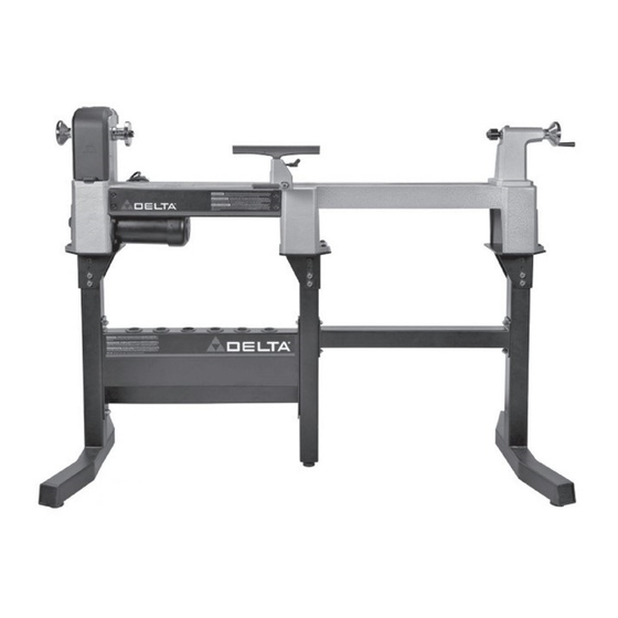
46-464 MIDI-LATHE STAND EXTENSION
IF YOU HAVE ANY QUESTIONS OR COMMENTS ABOUT THIS OR
ANY DELTA MACHINERY ACCESSORY, CALL US TOLL FREE AT
800-223-7278.
SAFETY INSTRUCTIONS
To reduce the risk of injury, read the tool instruction
manual before using any accessory. Failure to heed these warnings
may result in personal injury and serious damage to the tool and
the accessory. When servicing this tool, use only identical replace-
ment parts.
To reduce the risk of injury, turn tool off and
disconnect it from power source before installing and removing
accessories, before adjusting or when making repairs. an
accidental start-up can cause injury.
To reduce risk of injury this product should only be
used with Delta midi-lathes 46-455 and 46-460 and Delta lathe
stand 46-462 and Delta lathe extension bed 46-463.
46-464 PARTS (FIG. 1, FIG. 2)
a.
Lathe stand platform (1)
B. Extension cross brace (1)
C. Center support leg (1)
D. 3/8-16 x 1-1/2" (38 mm) hex head bolt (2)
E.
3/8-16 x 3-1/2" (89 mm) hex head bolt (5)
F.
3/8-16 nylock nut (7)
G. 3/8 flat washer (14)
h. Leveling foot and jam nut (1)
NOTE:
If you are assembling both the 46-462 Lathe Stand and
this 46-464 Lathe Stand Extension at the same time, refer to the
46-462 instruction sheet before proceeding to section Assembly
of Extension with the Stand in this sheet as directed.
ASSEMBLY
DISASSEMBLY OF THE STAND
1. Remove the lathe (i) Fig. 3 from the stand (J).
2. Remove the right side leg (K) Fig. 3 by removing both
sets of bolts, washers and nuts, located at (L) Fig. 4, that
attach leg to cross brace / tool holder (m).
3. set aside these parts to re-attach later on the very end of
the stand extension.
ASSEMBLY OF EXTENSION WITH THE STAND
NOTE: For ease of alignment, do not fully tighten nuts
until assembly is complete.
1. Bolt center support leg (C) Fig. 5 to cross brace/tool
holder (m) in bottom hole only (shown at (N)) using one
3/8-16 x 3-1/2" (89 mm) hex head bolt (E) Fig. 2, two 3/8
flat washers (G) Fig. 2 and one 3/8-16 nylock nut (F) Fig.
2.
2. Place flat washer on bolt and insert it through center support leg
(C) Fig. 5 and then through the hole (N) in tool holder. Place a
second flat washer on the bolt and fasten with the nylock nut.
3. make sure jam nut is on rubber leveling foot (h) Fig. 5 (inset)
as shown. screw in rubber leveling foot (h) as shown in Fig. 5.
tighten all the way down. height can be adjusted later.
4. attach extension brace (B) Figure 6 to center support leg (C) and
cross brace / tool holder (m) in two top holes (P) as shown, using
two 3/8-16 x 3-1/2" (89 mm) hex head bolts (E) Fig. 2, four 3/8
FoR UsE with DELta miDi-LathEs 46-455 aND 46-460 aND LathE staND 46-462
a
FiG. 1
F
G
i
FiG. 3
flat washers (G) Fig. 2 and two 3/8-16 nylock nuts (F) Fig. 2.
5. For each hole (P) Fig. 6, place washer on bolt and insert the bolt
through hole in extension brace (B), then through hole in center
support leg (C) and then through the cross brace / tool holder (m).
Place a second flat washer on the bolt and fasten with nylock nut.
NOTE: Figure 6 is shown from back of lathe stand.
NOTE: an additional Lathe stand Extension can be attached in a
similar manner using steps above. Do not attach more than two
Lathe stand Extensions.
N039890 - JULY09 - REV0
C
B
D
h
K
J
E
FiG. 2
L
m
L
FiG. 4
Advertisement
Table of Contents

Related Manuals for Delta 46-464


Summary of Contents for Delta 46-464
-
Page 1: Safety Instructions
NOTE: If you are assembling both the 46-462 Lathe Stand and this 46-464 Lathe Stand Extension at the same time, refer to the 46-462 instruction sheet before proceeding to section Assembly of Extension with the Stand in this sheet as directed. -
Page 2: Troubleshooting
NOTE: the stand height is adjustable by placing two bolts through two of the four holes (R) Fig. 8 in the lathe stand platform. Be sure the lathe mounting holes (s) Fig. 7 in top of the platform are facing to outside, away from tool holder as shown. -
Page 3: Warranty
FIVE YEAR LIMITED NEW PRODUCT WARRANTY DELta will repair or replace, at its expense and at its option, any new DELta machine, machine part, or machine accessory which in normal use has proven to be defective in workmanship or material,... -
Page 4: Depannage
DELta ou à un centre de réparation autorisé accompagné d'une preuve d'achat et dans les cinq ans de la date d'achat du produit, et fournisse à DELta une opportunité raisonnable de vérifier le défaut présumé par une inspection. -
Page 5: Instrucciones De Seguridad
46-455 y 46-460 marca Delta, con el soporte 46-462 marca Delta para tornos, y con el asiento de la extensión 46-463 marca Delta para tornos. PIEZAS DEL 46-464 (FIG. 1, FIG. 2) a. -
Page 6: Localizacion De Fallas
Para obtener asistencia para su máquina, visite nuestro sitio web en www.deltaportercable.com para tener acceso a una lista de centros de servicio o llame a la línea de ayuda de DELta machinery al 1-800- 223-7278. (En Canadá, llame al 1-800-463-3582.) - Page 7 (55) 5588 9377 estación de servicio autorizado DELta, con un comprobante de compra del producto, dentro del plazo de cinco años y dé a DELta una oportunidad (999) 928 5038 razonable de verificar el supuesto defecto mediante la realización de una inspección.
- Page 8 Delta Machinery, PO Box 2468, Jackson, TN 38302-2468 (800) 223-7278 - U.S. Ÿ (800) 463-3582 - CANADA www.deltaportercable.com Ÿ Copyright © 2008 Delta Machinery...
Need help?
Do you have a question about the 46-464 and is the answer not in the manual?
Questions and answers