
Subscribe to Our Youtube Channel
Related Manuals for Polytron HDI 2 SDI


Summary of Contents for Polytron HDI 2 SDI
- Page 1 HD IP Decoder – 2x IP/ASI in 2x SDI + IP HD IP Decoder – 2x IP/ASI into 2x SDI + IP HDI 2 SDI Bedienungsanleitung User Manual 0902162...
- Page 2 Montage- und Sicherheitshinweise...
- Page 3 Mounting and safety instructions...
- Page 4 ACHTUNG Diese Baugruppe enthält ESD-Bauteile! (ESD = Elektrostatisch empfindliches Bauteil) Eine elektrostatische Entladung ist ein elektrischer Stromimpuls, der, ausgelöst durch große Spannungsdifferenz, auch über ein normalerweise elektrisch isolierendes Material fließen kann. Um die Zuverlässigkeit von ESD-Baugruppen gewährleisten zu können, ist es notwendig, beim Umgang damit die wichtigsten Handhabungsregeln zu beachten: Elektrostatisch empfindliche Baugruppen dürfen nur an elektrostatisch geschützten Arbeitsplätzen (EPA) verarbeitet werden!
- Page 5 ATTENTION This module contains ESD components! (ESD = Electrostatic Sensitive Device). An electrostatic discharge is an electrical current pulse, which can flow also through an electrically insulated material, when triggered by large voltage difference. To ensure the reliability of ESD components, it is necessary to consider their most important handling rules: Electrostatic sensitive components can be processed only on electrostatic protected area (EPA)! ...
-
Page 6: Table Of Contents
Inhaltsverzeichnis / Directory Kapitel 1 - Produktübersicht / Chapter 1 - Product overview…………………………………………….. 7 1.1 Beschreibung / Description…………………………………………………………………………………… 7 1.2 Hauptmerkmale / Key features………………………………………………………………………………. 7 1.3 Blockdarstellung / Principle chart……………………………………………………………………………. 7 1.4 Technische Daten / Technical data………………………………………………………………………….. 8 Kapitel 2 - Gehäuse und Anschlüsse / Chapter 2 - Housing and connections………………………... 9 2.1 Darstellung der Frontseite / Front view………………………………………………………………………... -
Page 7: Kapitel 1 - Produktübersicht / Chapter 1 - Product Overview
ASI-Anschlüssen für Ein- und Ausgang ausgestattet. The HDI 2 SDI is a HD IP decoder in a 19" housing and is characterized by a small form factor (1 RU), high performance and low cost. The device supports IP and ASI signals on the input side. After decoding, two video channels are generated with HD/SD-SDI signals and two stereo audio signals are provided at each port. -
Page 8: Technische Daten / Technical Data
1.4 Technische Daten / Technical data 2x IP (MPTS/SPTS, 100M/1000M Ethernet RJ45, UDP-Protokoll / UDP protocol, Unicast/multicast) Eingang / Input 2x ASI bidirektional / ASI bidirectional, BNC 75 Ω Videoformat / Video format MPEG-2, MPEG-4 AVC/H.264 Schnittstelle / Interface 2x SDI (SD / HD) Videoauflösung 480i, 480p, 576i, 576p, 720p@50/59.94/60, 1080i@50/59.94/60... -
Page 9: Kapitel 2 - Gehäuse Und Anschlüsse / Chapter 2 - Housing And Connections
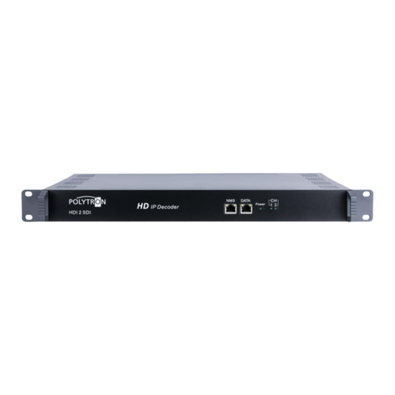
Kapitel 2 - Gehäuse und Anschlüsse / Chapter 2 - Housing and connections 2.1 Darstellung der Frontseite / Front view NMS: Netzwerk-Management-Anschluss / Network management port DATA: IP-Eingang und -Ausgang / IP input and output Netzkontroll-LED / Mains control LED CH1-CH2: LED leuchtet, wenn das Programm dekodiert wurde. -
Page 10: Kapitel 3 - Installationsanleitung / Chapter 3 - Installation Guide
Kapitel 3 - Installationsanleitung / Chapter 3 - Installation guide 3.1 Lieferumfang / Scope of delivery 1 x HDI 2 SDI HD IP Decoder 1 x Bedienungsanleitung / User manual 1 x Netzanschlusskabel / Power cord 3.2 Vorbereitung der Installation / Installation preparation Bei der Installation bitte den folgenden Ablauf und die Hinweise beachten. -
Page 11: Kapitel 4 - Webbasiertes Netzwerkmanagement-System / Chapter 4 - Web Nms Management
Kapitel 4 - Webbasiertes Netzwerkmanagement-System Chapter 4 - Web NMS management Alle Geräteeinstellungen werden über das webbasierte Netzwerkmanagement-System vorgenommen. All device settings are made via the web-based network management system. 4.1 Anmeldung / Login Den PC / das Notebook durch ein Standard-Netzwerkkabel mit der NMS-Buchse verbinden. Falls ein Proxyserver verwendet wird, so ist dieser in den Netzwerkverbindungen zu deaktivieren. -
Page 12: Betrieb / Operation
4.2 Betrieb / Operation 4.2.1 Zusammenfassung / Summary Nach Bestätigung der Anmeldedaten wird die folgende Menüansicht als Abbildung-2 angezeigt. After confirming the credentials, the following menu view will be displayed as Figure-2. Systeminformation System information Eingangsstatus der beiden IP- und ASI-Streams. Input status of the two IP and ASI streams. -
Page 13: Einstellungen / Settings
4.2.2 Einstellungen / Settings Parameter / Parameters -> Decoder: In der Auswahlleiste links auf „Decoder“ klicken, so wird ein Dialogfeld geöffnet, über das folgende Parameter konfiguriert werden: ASI-Eingang bzw. -Ausgang / Mux / Allgemein / PID PASS / Decoder / System. In the selection bar on the left, click on "Decoder"... - Page 14 Decoder -> Mux-Einstellungen / Mux settings: Nach einem Klick auf “Mux” werden die entsprechenden Einstellmöglichkeiten gemäß Abbildung-4 angezeigt. After a click on "Mux" the corresponding settings are displayed according to Figure-4. 4 Auswahlmöglichkeiten / Options Eingangsbereich / Input Area Ausgangsbereich / Output Area Einstellbereich / Setting area Abbildung / Figure-4...
- Page 15 Programmanpassung / Program modification Die gemultiplexten Programminformationen können durch Anklicken des Programms im „Ausgangsbereich“ geändert werden. Klickt man beispielsweise auf „ “, so wird ein Dialogfeld (Abbildung-5) geöffnet, in dem neue Informationen eingeben werden können. The multiplexed program information can be modified by clicking the program in the ”output area”. For example, when clicking “...
- Page 16 Decoder -> PID Pass: Nach Klicken auf „PID Pass“ wird das Eingabefenster angezeigt, in dem PIDs hinzugefügt werden, um am Ausgang ausgegeben zu werden. In einigen Fällen gibt es PIDs, welche keinem Programm zugeordnet werden können (z.B. EPG, NIT-Tabellen, usw.). Diese sollen aber am Ausgang ohne Veränderungen ausgegeben werden. After clicking on "PID Pass", the input window is displayed, in which PIDs are added to be issued at the output.
- Page 17 Decoder -> Decoder: In der Auswahlleiste auf „Decoder“ klicken, so wird ein Dialogfeld (Abbildung-8) geöffnet, über das die Parameter des Decoders eingestellt werden. If clicking on "Decoder", a dialog box (Figure-8) will be opened to set the parameters of the decoder. Auswahl der Programme, die vom Decoder gemultiplext werden.
- Page 18 Decoder -> System: Durch einen Klick auf den Menüpunkt „System“ werden die aktuellen Moduldaten angezeigt, siehe Abbildung-9. Click on the menu item "System" to display the current module data, see Figure-9. Abbildung / Figure-9...
- Page 19 Parameter / Parameters -> Konfiguration IP-Eingang / Configuration IP input: Der Decoder HDI 2 SDI verfügt über zwei individuell konfigurierbare IP-Eingänge. In der Auswahlleiste links auf „IP Input“ klicken – es wird ein Dialogfeld (Abbildung-10) geöffnet, über das die IP-Eingänge konfiguriert werden können.
- Page 20 Parameter / Parameters -> Konfiguration IP-Ausgang / Configuration IP output: Der Decoder HDI 2 SDI verfügt über einen konfigurierbaren IP-Ausgang. In der Auswahlleiste links auf „IP Output“ klicken – es wird ein Dialogfeld (Abbildung-11) geöffnet, über das der IP-Ausgang (IP-Stream und MPTS) konfiguriert werden kann.
- Page 21 System -> Netzwerk / Network: Nach einem Klick auf „Netzwerk" wird die Eingabemaske (Abbildung-12) angezeigt, in der man die Netzwerkparameter einstellen kann. After clicking on "Network", the input mask (Figure-12) is displayed in which it is possible to enter the network parameters.
- Page 22 System -> NMS Passwort / Password: In der Auswahlleiste links auf „Password“ klicken, so wird ein Dialogfeld (Abbildung-13) geöffnet, über das die Einstellungen betreffend Login und Passwortschutz vorgenommen werden können. In the selection bar on the left, click on "Password" to open a dialog box (Figure-13) where the settings for login and password protection can be made.
- Page 23 System -> Konfiguration / Configuration: In der Auswahlleiste links auf „Configuration“ klicken, so wird ein Dialogfeld (Abbildung-14) geöffnet, über das die maßgebliche und abschließende Gerätekonfiguration („Save / Restore / Factory Set / Backup / Load“) vorgenommen werden kann. Click on "Configuration" in the selection bar on the left-hand side and a dialog box (Figure-14) will open, where the relevant and final device configuration ("Save / Restore / Factory Set / Backup / Load") can be made.
- Page 24 System -> Firmware: In der Auswahlleiste links auf „Firmware“ klicken, so wird ein Dialogfeld (Abbildung-15) geöffnet, über das ein Firmware-Update vorgenommen werden kann. Mittels „Browse” den entsprechende Order mit dem Firmware-Update suchen und die Datei auswählen. Danach auf „Upgrade“ klicken. Click on "Firmware"...
- Page 25 System -> Log: In der Auswahlleiste links auf „Log“ klicken, so wird ein Dialogfeld (Abbildung-16) geöffnet, über das die „Log-Daten“ (Kernel- und System-Log) überprüft werden können. Click on "Log" in the selection bar on the left-hand side and a dialog box (Figure-16) will open, which allows you to check the "Log data"...
- Page 26 Notizen / Notes:...
- Page 27 Notizen / Notes:...
- Page 28 Technische Hotline Technical hotline + 49 (0) 70 81 / 1702 - 0 Telefax + 49 (0) 70 81 / 1702 - 50 Internet http://www.polytron.de eMail info@polytron.de Technische Änderungen vorbehalten Subject to change without prior notice Copyright © Polytron-Vertrieb GmbH...
Need help?
Do you have a question about the HDI 2 SDI and is the answer not in the manual?
Questions and answers