
Subscribe to Our Youtube Channel
Related Manuals for Polytron HDS 2 C01


Summary of Contents for Polytron HDS 2 C01
- Page 1 2x(4x) SDI/ASI in DVB-C(T) / ASI / IP SDI Encoder/Modulator HDS 2 C(T)01 HDS 4 C(T)01 Bedienungsanleitung User manual 0901960...
-
Page 2: Table Of Contents
Inhaltsverzeichnis / Table of Contents 3 / 28 1. Montage- und Sicherheitshinweise / Mounting and safety instructions 2. Allgemeine Funktionsbeschreibung, Gerätevarianten und Applikationsbeispiel General functional description, device variants and application example 4 / 29 5 / 30 3. Funktions- und Bedienelemente / Function and control elements 6 / 31 4. -
Page 3: Montage- Und Sicherheitshinweise / Mounting And Safety Instructions
1. Montage- und Sicherheitshinweise... -
Page 4: General Functional Description, Device Variants And Application Example
Je nach Einsatzfall sind die Geräte hardwareseitig vorkonfiguriert. Über das integrierte Bedieninterface (Bedientas- ten oder Webbrowser) können die Betriebsparameter an die benötigte Applikation angepasst werden. HINWEIS Nach einem Netzausfall bleiben alle Daten erhalten. Gerätevarianten HDS 2 C01 5741671 2x SDI/ASI in DVB-C / ASI / IP HDS 4 C01 5741656... -
Page 5: Funktions- Und Bedienelemente / Function And Control Elements
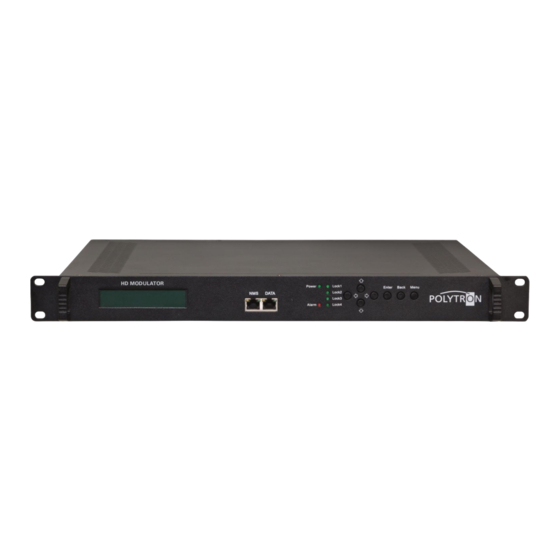
3. Funktions- und Bedienelemente Frontansicht Abb. 2: Frontansicht HD Modulator Abb. 3: Frontansicht - Auszug Bedienelemente Taste nach oben im Menü Taste nach unten im Menü Taste nach links im Menü Taste nach rechts im Menü Taste „Enter“ (Auswahl bestätigen) Taste „Back“... -
Page 6: Blockschaltbild / Block Diagram
Rückansicht Abb. 4: Rückansicht SDI IN 1 / SDI IN 2 SDI-Eingänge (bis zu 4 Signale sind aufschaltbar) RF IN HF-Durchschleifeingang (zum Zusammenschalten mit externen Signalquellen) RF OUT HF-Ausgang ASI IN ASI-Transportstrom-Eingang ASI OUT 1 / ASI OUT 2 ASI-Transportstrom-Ausgänge Netzschalter / Netzsicherung / Netzanschluss 4. -
Page 7: Inbetriebnahme Des Hds (Ohne Konfiguration) / Launch Of The Hds (Without Configuration)
DVB-T A/B/E* ASI OUT MPEG-2 / SDI 1/1 MPEG-4 HD ASI OUT Encoding SPTS1/SPTS2/SPTS3/SPTS4 IP OUT MPEG-2 / SDI 1/2 MPEG-4 HD Encoding DVB-T Modulator MPEG-2 / SDI 2/1 MPEG-4 HD Encoding DVB-T Modulator MPEG-2 / SDI 2/2 MPEG-4 HD Encoding RF IN ASI IN... -
Page 8: Grundeinstellungen Im Auslieferzustand / Default Settings At Delivery State
Der Auslieferzustand kann jederzeit durch „Factory set“ hergestellt werden (siehe Abschnitt 8.9). Alle Transportstro- minformationen werden neutral vorgegeben und können den Erfordernissen des Kabelnetzbetreibers angepasst werden. Die Grundeinstellungen der Geräte sind nachfolgend dargestellt: HDS 2 C01 / HDS 4 C01 HDS 2 T01 / HDS 4 T01 Netzwerk* IP Adresse 192.168.001.225... -
Page 9: Manuelle Programmierung Am Gerät / Manual Programming On The Device
7. Manuelle Programmierung am Gerät LCD Anzeige nach dem Einschalten DVB-C / DVB-T Start up Please wait … Modulation des Ausgangssignals (DVB-C / DVB-T) Kanal (A, B, C, D für DVB-C / A, B für DVB-T) DVB-C 750.00MHz Ausgangsfrequenz des angezeigten Kanals Datenrate des Programms (P1, P2, P3, P4 für 4-fach P1: 12.57M P2: 0.00M... - Page 10 Übersicht Untermenüs für die Maximalkonfiguration Input sets DVB-C / DVB-T 1 Status 2 Input sets 2.1.1 Program 1 „Enter“ 2.1.2 Program 2 2.1 Input 1 „Enter“ 2.2 Input 2 2.2.1 Program 1 2.2.2 Program 2 2.3 Input 3 Nach Auswahl des gewünschten Eingangs und Programms erfolgen die programmspezifischen Einstellungen. Video 2.1.1 Program 1 Video in status...
- Page 11 Modulator DVB-C Nach Auswahl des gewünschten Ausgangs erfolgen die modulator- 3 Modulator spezifischen Einstellungen. 4 TS config „Enter“ RF On Enable, Disable Standard: Enable Standard J.83A (DVB-C), J.83B, J.83C Standard: J.83A 3.1 Output A Constellation 16 QAM, 32 QAM, 64 QAM, 3.2 Output B 128 QAM, 256 QAM Standard: 256 QAM...
- Page 12 DVB-C / DVB-T TS config Nach Auswahl des gewünschten Ausgangs erfolgen die 3 Modulator Transportstrom-Einstellungen. 4 TS config „Enter“ Output A, B, C, D, E für DVB-C / A, B, E für DVB-T TSID 0x0000…0xffff Standard: 0x1 4.1 Output A ONID 0x0000…0xffff Standard: 0x1...
- Page 13 IP Stream DVB-T (4xSPTS) 5.1 NMS Nach Wahl des gewünschten Ausgangs erfolgen die Streaming- 5.2 IP Stream Einstellungen. „Enter“ Data enable Enable (an), Disable (aus) Standard: Enable Null PKT Filter Yes, No Standard: Yes 5.2.1 Output SPTS1 Output IP Multicast Adresse Stream Standard: 5.2.2 Output SPTS2 224.002.002.002...
-
Page 14: Programmierung Über Das Ethernet-Interface (Nms) / Programming Via The Ethernet Interface (Nms)
8. Programmierung über das Ethernet-Interface (NMS) Sollen Änderungen an der Grundkonfiguration via Ethernet-Interface vorgenommen werden, so ist die jeweilige HTML-Bedienoberfläche über einen angeschlossenen Computer aufzurufen. Als Bedienprogramm wird ein Internet- browser benötigt. 8.1 Netzwerkverbindung zum Computer Systemvoraussetzungen: PC/Laptop mit Ethernet-Schnittstelle 10/100Mbps ... -
Page 15: Statusanzeige (Welcome) / Status Indication (Welcome)
Input 1 Input 1 SDI 1 Encoder 1 SDI 1 Encoder 1 SDI 2 Encoder 2 Input 2 Input 2 Abb. 10: Eingangskonfiguration HDS 4 C01 / HDS 4 T01 Abb. 11: Eingangskonfiguration HDS 2 C01 / HDS 2 T01... - Page 16 In diesem Menü erfolgt die Einstellung der Eingänge „SDI 1“ und „SDI 2“ für den Eingang 1 („Input 1“). Die folgenden Einstellhinweise gelten in gleicher Weise für die Programmierung des Einganges 2 (Input 2). DVB-C DVB-T Abb. 12: Festlegung der Encoderparameter für die Eingangskanäle des HDS 4 C01 Abb.
- Page 17 H.264 Level Festlegung des Levels entsprechend der spezifischen Anwendung. Dies bezieht sich auf das maximale Mak roblocking, die Framegröße und die maximale Video-Bitrate. Level 2.2, Level 3, Level 3.1, Level 3.2, Level 4, Standard: Level 3.1 Level 4.1, Level 4.2, Level 5, Level 5.1 Auto Config Durch Anwahl dieser Selektionsbox wird die Auflösung des Signals automatisch bestimmt und festgelegt.
-
Page 18: Menü „Asi Input" / Menu „Asi Input
8.4 Menü „ASI Input“ In diesem Menü erfolgt die Einstellung und Zuweisung des ASI Eingangssignals des HDS-Gerätes. Bei der Einstellung kann zwischen dem „Passthrough“ - Mode und dem „Multiplex“- Mode gewählt werden. Beim „Passthrough“ - Mode werden alle Programme des Eingangs auch auf den gewählten Ausgang durchgereicht, der „Multiplex“... -
Page 19: Menü „Nit" / Menu "Nit
Button „All Input“ Wählt alle im Eingang angezeigten Programme aus. Button „All Output“ Wählt alle im Ausgang angezeigten Programme aus. Parse timeout Mit Einstellung des Wertes wird die Auslesezeit des ASI-Eingangsdatenstroms begrenzt. Die Eingabe erfolgt in Sekunden, als Standard-Auslesezeit werden 200 Sekunden empfohlen. HINWEIS Alle in diesem Fenster durchgeführten Einstellungen werden automatisch nach erfolgter Einstellung übernommen. -
Page 20: Menü „Vct" / Menu "Vct
DVB-C DVB-T Abb. 18: Konfigurationsmenü NIT und LCN Programme des HDS 4 C01 Abb. 19: Konfigurationsmenü NIT und LCN für Programme des HDS 4 T01 Nach Fertigstellung aller NIT- und LCN-Konfigurationen der einzelnen Modulatoren muss der Button „Update NIT“ betätigt werden. Dadurch erfolgt die Übernahme der eingestellten Konfigurationen in den Ausgangstransportstrom. 8.6 Menü... -
Page 21: Menü „Modulator" Dvb-C / Menu „Modulator" Dvb-C
SPTS1, SPTS2, SPTS3, SPTS4 und MPTS Hier werden die Zieladresse (Multicast-Adresse), der Port und das Sendeprotokoll sowie die „Time to Live“ (Gül tigkeitsdauer) für jeden Stream spezifiziert. DVB-C DVB-T 224.002.002.002 IP Adresse: 224.002.002.002 Standard Multicast IP-Adresse: 2234 2234 Standard Port SPTS1: Port SPTS1 2236 2236... -
Page 22: Menü „Modulator" Dvb-T / Menu „Modulator" Dvb-T
RF Outlevel Konfiguration des Ausgangspegels der Modulatorsignale. -30 dBm…-10 dBm in 0,1 dB-Schritten Standard: -10 dBm (99 dBµV) HINWEIS -30 dBm = 79 dBµV -25 dBm = 84 dBµV -20 dBm = 89 dBµV -15 dBm = 94 dBµV -10 dBm = 99 dBµV 8.9 Menü... -
Page 23: Menü „Save/Restore" / Menu „Save/Restore
RF Frequency A, B Festlegung der Frequenz der Ausgangssignale. 30…960 MHz Standard: 650,00 MHz RF Outlevel Konfiguration des Ausgangspegels der Modulatorsignale. -30 dBm…-10 dBm in 0,1 dB-Schritten Standard: -10 dBm (99 dBµV) HINWEIS -30 dBm = 79 dBµV -25 dBm = 84 dBµV -20 dBm = 89 dBµV -15 dBm = 94 dBµV -10 dBm = 99 dBµV... -
Page 24: Menü „Reboot" / Menu „Reboot
8.11 Menü „Reboot“ Durch Betätigen des Buttons „Reboot“ wird ein Neustart des Encoder/Modulators durchgeführt. Bestimmte Einstel- lungen erfordern die Durchführung eines Reboots, um die Übernahme der eingestellten Parameter zu bewirken. Dies betrifft Änderungen am Management-Port und Firmware-Updates. Nach dem Laden einer gespeicherten Konfi- guration wird automatisch ein Reboot durchgeführt. -
Page 25: Menü „Network" / Menu „Network
8.13 Menü „Network“ Im Menü „Network“ wird das Ethernet-Interface für das Management des Gerätes via Webbrowser konfiguriert. Es müssen die Einstellungen der IP-Adresse, Subnetzmaske, Gateway und des Management Ports an das örtliche Netzwerk angepasst und damit individualisiert werden. Abb. 27: Konfiguration des Management-Ports des HDS 4 C01 IP Address Einstellung der IP Adresse für den Webbrowser Zugang. -
Page 26: Menü „Backup/Load" / Menu „Backup/Load
Current UserName Aktuellen Benutzernamen eingeben (Werkseinstellung: admin). Current Password Aktuelles Passwort eingeben (Werkseinstellung: admin). New UserName Neuen Benutzernamen eingeben. New Password Neues Passwort eingeben. Confirm New Password: Neues Passwort bestätigen. Selektionsbox „Keyboard and LCD Lock“ Durch Anwahl dieser Selektionsbox wird der Passwortschutz für die Bedientasten an der Frontseite des Gerä- tes und für den Web-Zugang aktiviert. -
Page 27: Logout Exit" / „Logout Exit
8.16 „Logout Exit“ Die Logout- und Exit-Möglichkeit besteht auf jeder Menüseite während der Programmierung via Web-Browser. Abb. 30: Logout/Exit des HDS 4 C01... - Page 28 1. Mounting and safety instructions...
- Page 29 (keypad or web browser). NOTE After a power failure, all data is retained. Device variants HDS 2 C01 5741671 2x SDI/ASI in DVB-C / ASI / IP HDS 4 C01...
- Page 30 3. Function and control elements Front view Pic. 2: Front view HD Modulator Pic. 3: Front view - Zoom on controls Button up in the menu Button down in the menu Button left in the menu Button right in the menu Button „Enter“...
- Page 31 Rear view Pic. 4: Rear view SDI IN 1 / SDI IN 2 SDI inputs (up to 4 signals can be connected) RF IN RF loop-through input (for interconnection with external signal sources) RF OUT RF output ASI IN ASI transport stream input ASI OUT 1 / ASI OUT 2 ASI transport stream outputs Mains switch / mains fuse / mains connection...
- Page 32 DVB-T A/B/E* ASI OUT MPEG-2 / SDI 1/1 MPEG-4 HD ASI OUT Encoding SPTS1/SPTS2/SPTS3/SPTS4 IP OUT MPEG-2 / SDI 1/2 MPEG-4 HD Encoding DVB-T Modulator MPEG-2 / SDI 2/1 MPEG-4 HD Encoding DVB-T Modulator MPEG-2 / SDI 2/2 MPEG-4 HD Encoding RF IN ASI IN...
- Page 33 The delivery status can be established at any time by "Factory set" (see section 8.9). All transport stream information is given neutral and can be adapted to the requirements of the cable network operator. The basic settings of the devices are shown below: HDS 2 C01 / HDS 4 C01 HDS 2 T01 / HDS 4 T01 Network* NMS IP Address 192.168.001.225...
- Page 34 7. Manual programming on the device LCD display after switching on DVB-C / DVB-T Start up Please wait … Modulation of the output signal (DVB-C / DVB-T) Channel (A, B, C, D for DVB-C / A, B for DVB-T) DVB-C 750.00MHz Output frequency of the displayed channel Data rate of the program (P1, P2, P3, P4 for 4way...
- Page 35 Overview of submenus for maximum configuration Input sets DVB-C / DVB-T 1 Status 2 Input sets 2.1.1 Program 1 „Enter“ 2.1.2 Program 2 2.1 Input 1 „Enter“ 2.2 Input 2 2.2.1 Program 1 2.2.2 Program 2 2.3 Input 3 After selecting the desired input and program, the program-specific settings are made. Video 2.1.1 Program 1 Video In Status...
- Page 36 Modulator DVB-C After selecting the desired output, the modulator-specific settings are 3 Modulator made. 4 TS config „Enter“ RF On Enable, Disable Standard: Enable Standard J.83A (DVB-C), J.83B, J.83C Standard: J.83A 3.1 Output A Constellation 16 QAM, 32 QAM, 64 QAM, 3.2 Output B 128 QAM, 256 QAM Standard: 256 QAM...
- Page 37 DVB-C / DVB-T TS config After selecting the desired output, the transport stream settings are 3 Modulator made. 4 TS config „Enter“ Output A, B, C, D, E for DVB-C / A, B, E for DVB-T 4.1 Output A TSID 0x0000…0xffff Standard: 0x1 4.2 Output B...
- Page 38 IP Stream DVB-T (4xSPTS) 5.1 NMS After selecting the desired output, the streaming settings are made. 5.2 IP Stream Data Enable Enable (on), Disable (off) Standard: Enable „Enter“ Null PKT Filter Yes, No Standard: Yes Output IP Multicast Address Stream Standard: 5.2.1 Output SPTS1 224.002.002.002...
- Page 39 8. Programming via the Ethernet interface (NMS) If changes are to be made to the basic configuration via the Ethernet interface, the respective HTML user interface must be accessed via a connected computer. An Internet browser is required as an operating program. 8.1 Network connection to the computer System requirements: ...
- Page 40 Input 1 SDI 1 Encoder 1 SDI 1 Encoder 1 SDI 2 Encoder 2 Input 2 Input 2 Pic. 10: Input configuration HDS 4 C01 / HDS 4 T01 Pic. 11: Input configuration HDS 2 C01 / HDS 2 T01...
- Page 41 In this menu, the "SDI 1" and "SDI 2" inputs for “Input 1" are set. The following setting instructions apply in the same way for programming “Input 2”. DVB-C DVB-T Pic. 12: Defining the encoder parameters for the input channels of the HDS 4 C01 Pic.
- Page 42 H.264 Level Definition of the level according to the specific application. This refers to the maximum Macro blocking, the frame size, and the maximum video bit rate. Level 2.2, Level 3, Level 3.1, Level 3.2, Level 4, Standard: Level 3.1 Level 4.1, Level 4.2, Level 5, Level 5.1 Auto Config By selecting this selection box the resolution of the signal is automatically determined and fixed.
- Page 43 8.4 Menu „ASI Input“ In this menu, the ASI input signal of the HDS device is set and assigned. You can choose between the "Passthrough" mode and the "Multiplex" mode. In "Passthrough" mode, all programs of the input are passed through to the selected output, while in "Multiplex" mode, certain programs can be selected and passed on to the selected output.
- Page 44 Button „All Input“ Selects all programs displayed in the input. Button „All Output“ Selects all programs displayed in the output. Parse timeout Setting the value limits the readout time of the ASI input data stream. It is entered in seconds, 200 seconds are recommended as the standard readout time.
- Page 45 DVB-C DVB-T Pic. 18: Configuration menu NIT and LCN programs of the HDS 4 C01 Pic. 19: Configuration menu NIT and LCN programs of the HDS 4 T01 After completion of all NIT and LCN configurations of the individual modulators, the button "Update NIT" has to be pressed.
- Page 46 SPTS1, SPTS2, SPTS3, SPTS4 and MPTS The destination address (multicast address), the port and transmission protocol as well as the “time to live” (validity period) for each stream are specified here. DVB-C DVB-T 224.002.002.002 IP Address: 224.002.002.002 Standard Multicast IP Address: 2234 2234 Standard Port SPTS1:...
- Page 47 RF Outlevel Configuration of the output level of the modulator signals. -30 dBm…-10 dBm in 0,1 dB steps Standard: -10 dBm (99 dBµV) NOTE -30 dBm = 79 dBµV -25 dBm = 84 dBµV -20 dBm = 89 dBµV -15 dBm = 94 dBµV -10 dBm = 99 dBµV 8.9 Menu „Modulator“...
- Page 48 RF Frequency A, B Definition of the frequency of the output signals. 30…960 MHz Standard: 650,00 MHz RF Outlevel Configuration of the output level of the modulator signals. -30 dBm…-10 dBm in 0,1 dB steps Standard: -10 dBm (99 dBµV) NOTE -30 dBm = 79 dBµV -25 dBm = 84 dBµV...
- Page 49 8.11 Menu „Reboot“ Pressing the "Reboot" button restarts the encoder/modulator. Certain settings require the execution of a reboot in order to take over the set parameters. This affects management port changes and firmware updates. After loading a saved configuration, a reboot is automatically performed. Pic.
- Page 50 8.13 Menu „Network“ In the "Network" menu, the Ethernet interface for the management of the device is configured via the web browser. The settings of the IP address, subnet mask, gateway and the management port must be adapted to the local net- work and thus customized.
- Page 51 Current UserName Enter the current user name (default: admin). Current Password Enter current password (factory setting: admin). New UserName Enter new user name. New Password Enter new password. Confirm New Password: Confirm new password. Selection box „Keyboard and LCD Lock“ Selecting this selection box activates the password protection for the operating buttons on the front of the device and for web access.
- Page 52 8.16 „Logout Exit“ The logout and exit option is available on each menu page during programming via web browser. Pic. 30: Logout/Exit of the HDS 4 C01...
-
Page 53: Technische Daten / Technical Data
9. Technische Daten / Technical data Typ / Type HDS 2 C01 HDS 4 C01 HDS 2 T01 HDS 4 T01 Artikel-Nr. / Article no. 5741671 5741656 5741661 5741645 Encoder Video Videoformat / Video Format MPEG2, MPEG4 AVC/H.264 MPEG2, MPEG4 AVC/H.264... - Page 54 Notizen / Notes...
- Page 55 Notizen / Notes...
- Page 56 Technische Hotline Technical hotline + 49 (0) 70 81 / 1702 - 0 Telefax + 49 (0) 70 81 / 1702 - 50 Internet http://www.polytron.de eMail info@polytron.de Technische Änderungen vorbehalten Subject to change without prior notice Copyright © Polytron-Vertrieb GmbH...
Need help?
Do you have a question about the HDS 2 C01 and is the answer not in the manual?
Questions and answers